TRENDnet TEG-2248WS User Manual
52-port gigabit web-based smart switch
Hide thumbs
Also See for TEG-2248WS:
- User manual (76 pages) ,
- Quick installation manual (10 pages) ,
- Specifications (3 pages)
Table of Contents
Advertisement
Quick Links
Download this manual
See also:
User Manual
Advertisement
Table of Contents

Related Manuals for TRENDnet TEG-2248WS


Summary of Contents for TRENDnet TEG-2248WS
-
Page 2: Fcc Warning
FCC Warning This equipment has been tested and found to comply with the regulations for a Class A digital device, pursuant to Part 15 of the FCC Rules. These limits are designed to provide reasonable protection against harmful interference when the equipment is operated in a commercial environment. - Page 3 UL Warning a) Elevated Operating Ambient Temperature- If installed in a closed or multi-unit rack assembly, the operating ambient temperature of the rack environment may be greater than room ambient. Therefore, consideration should be given to installing the equipment in an environment compatible with the manufacturer's maximum rated ambient temperature (Tmra).
-
Page 4: Table Of Contents
TABLE OF CONTENT Introduction..................3 Switching Technology ..............3 VLAN (Virtual Local Area Network)..........4 Features.................... 5 Unpacking and Installation ..............9 Unpacking..................9 Installation ..................9 Rack Mounting ................10 Connecting Network Cable............11 AC Power..................11 Identifying External Components ............13 Front Panel.................. - Page 5 Toolbar................... 24 Configuring the Switch ..............25 Login....................25 Setup Menu ..................27 Configuring Setup Setting.............. 28 Port Settings................28 VLAN Settings (Virtual Local Area Network) ......31 Trunk Setting ................32 Device Status ................33 Statistic..................33 System Setting ................34 Trap Setting................
-
Page 6: Introduction
INTRODUCTION This chapter describes features 48+4G-Port 10/100/1000Mbps Gigabit Ethernet Web Smart Switch and some background information about Ethernet/Fast Ethernet/Gigabit Ethernet switching technology. Switching Technology Another approach to pushing beyond the limits of Ethernet technology is the development of switching technology. A switch bridges Ethernet packets at the MAC address level of the Ethernet protocol transmitting among connected Ethernet or Fast Ethernet LAN segments. -
Page 7: Vlan (Virtual Local Area Network)
VLAN, and is the one supplied in the Switch. Limitations TEG-2248WS has 2 port groups for VLAN settings which are mutually exclusive. Ports from 1 through 24 are in one group and have no limitations on the VLAN that can be set up within the group. Ports from 25 to 52 are in the second group. - Page 8 Features 48×10/100Mbps Auto-Negotiation Fast Ethernet RJ45 ports 2×10/100/1000Mbps Auto-Negotiation Gigabit RJ45 ports 2×mini-GBIC ports All RJ45 ports support auto MDI/MDIX, so there is no need to use cross-over cables or an up-link port Full/half duplex transfer mode for 10/100Mbps RJ45 port Full duplex transfer mode for Gigabit port Store-and-Forward switching scheme capability to support rate adaptation and ensure data integrity...
-
Page 10: Unpacking And Installation
UNPACKING AND INSTALLATION This chapter provides unpacking and installation information for the Switch. Unpacking Open the shipping cartons of the Switch and carefully unpacks its contents. The carton should contain the following items: One 48+4G-Port 10/100/1000Mbps Gigabit Ethernet Web Smart Switch One AC power cord, suitable for your area’s electrical power connections Four rubber feet to be used for shock cushioning... -
Page 11: Rack Mounting
Leave at least 10cm of space at the front and rear of the hub for ventilation. Install the Switch on a sturdy, level surface that can support its weight, or in an EIA standard-size equipment rack. For information on rack installation, see the next section, Rack Mounting. -
Page 12: Connecting Network Cable
Connecting Network Cable The Switch supports 10Mbps Ethernet or 100Mbps Fast Ethernet and it runs both in half and full duplex mode using two pair of Category 5 cable. The Switch also supports 2-Ports 1000Mbps Gigabit Ethernet that runs in Auto-negotiation mode and 10Mbps Ethernet or 100Mbps Fast Ethernet that runs both in half and full duplex mode and 1000Mbps Gigabit Ethernet runs in full duplex mode using four pair of Category 5 Cable. -
Page 14: Identifying External Components
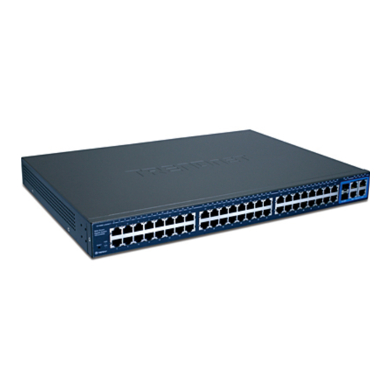
IDENTIFYING EXTERNAL COMPONENTS This chapter describes the front panel, rear panel, and LED indicators of the Switch. Front Panel The figure below shows the front panels of the Switch. Figure 3. Front panel of 48+4G-port Gigabit Ethernet Switch LED Indicator: Comprehensive LED indicators display the status of the switch and the network (see the LED Indicators chapter below). -
Page 15: Rear Panel
mini-GBIC Ports (Port 51~52): The Switch is equipped with two mini-GBIC ports, supported optional 1000BASE-SX/LX mini-GBIC module. Note: When the port was set to “Forced Mode”, the Auto MDI/MDIX will be disabled. Reset: The Reset button is to reset all the setting back to the factory default. -
Page 16: Understanding Led Indicators
UNDERSTANDING LED INDICATORS The front panel LEDs provides instant status feedback, and, helps monitor and troubleshoot when needed. Figure 5. LED indicators of the Switch Power and System LEDs POWER: Power Indicator : When the Power LED lights on, the Switch is receiving power. : When the Power turns off or the power cord has improper connection. -
Page 17: Ports 1~48 10/100M Status Leds
Ports 1~48 10/100M Status LEDs Link/ACT: Link/Activity : When the Link/ACT LED lights on, the respective port is successfully connected to an Ethernet network. Blinking : When the Link/ACT LED is blinking, the port is transmitting or receiving data on the Ethernet network. : No link. -
Page 18: Ports 51~ 52 Mini-Gbic Status Leds
Ports 51~ 52 mini-GBIC Status LEDs Link/ACT: Link/Activity : When the mini-GBIC module is installed and connected to a network, the Link/ACT LED lights on. Blinking : When the LED is blinking, the mini-GBIC module is receiving data on a network. -
Page 19: Configuration
CONFIGURATION Through the Web Browser you can configure the Switch such as VLAN, Trunking, QoS… etc. With the attached Web Management Utility, you can easily discover all the Web Management Switch, assign the IP Address, changing the password and upgrading the new firmware. Installing the Web Management Utility The following gives instructions guiding you through the installations of the Web Management utility. -
Page 20: Discovery List
Figure 6. Web Management Utility The Web Management Utility was divided into four parts, Discovery List, Monitor List, Device Setting and Toolbar function, for details instruction, follow the below section. Discovery List This is the list where you can discover all the Web management devices in the entire network. -
Page 21: Monitor List
System word definitions in the Discovery List: MAC Address: Shows the device MAC Address. IP Address: Shows the current IP address of the device. Protocol version: Shows the version of the Utility protocol. Product Name: Shows the device product name. System Name: Shows the appointed device system name. - Page 22 View Trap: The Trap function can receive the events that happen from the Web Management Switch in the Monitor List. There is a light indicator behind the “View Trap” button, when the light indicates in green, it means that there is no trap transmitted, and else when it indicates in red, it means that there is new trap transmitted, this is to remind us to view the trap.
-
Page 23: Device Setting
Device Setting You can set the device by using the function key in the Device Setting Dialog box. Configuration Setting: In this Configuration Setting, you can set the IP Address, Subnet Mask, Gateway, Set Trap to (Trap IP Address), System name and Location. Select the device in the Discovery list or Monitor List and press this button, then the Configuration Setting window will pop out as Figure 9, after filling up the data that you want to change, you must fill up the... - Page 24 Figure 10. Password Change Firmware Upgrade: When the device has a new function, there will be a new firmware to update the device, use this function to update. Figure 11. Web Access: Double click the device in the Monitor List or select a device in the Monitor List and press this “Web Access”...
-
Page 25: Toolbar
Toolbar The toolbar in the Web Management Utility have four main tabs, File, View, Options and Help. In the “File TAB”, there are Monitor Save, Monitor Save As, Monitor Load and Exit. Monitor Save: To record the setting of the Monitor List to the default, when you open the Web Management Utility next time, it will auto load the default recorded setting. -
Page 26: Configuring The Switch
Configuring the Switch The 48+4G-Port 10/100/1000Mbps Gigabit Ethernet Web Smart Switch has a Web GUI interface for smart switch configuration. The Switch can be configured through the Web Browser. A network administrator can manage, control and monitor the switch from the local LAN. - Page 27 Open Internet Explorer 5.0 or above Web browser. Enter IP address http://192.168.0.1 (the factory-default IP address setting) to the address location. Figure 12. Or through the Web Management Utility, you do not need to remember the IP Address, select the device shown in the Monitor List of the Web Management Utility to settle the device on the Web Browser.
-
Page 28: Setup Menu
Figure 14. Device Status Setup Menu When the main page appears, find the Setup menu in the left side of the screen (Figure 15). Click on the setup item that you want to configure. There are eleven options: Port Settings, VLAN Settings, Trunk Setting, Device Status, Statistic, System Settings, Trap Setting, Password Setting, Backup Setting and Reset Setting as shown in the Main Menu screen. -
Page 29: Configuring Setup Setting
Figure 15. Setup menu Configuring Setup Setting Find that there are four items, including Port Settings, VLAN Settings and Trunk Settings in Setup menu. Port Settings In Port Settings menu (Figure 16), this page will show each port’s status, press the ID parameter to set each port’s Speed, Flow Control, and QoS priority. - Page 30 Figure 16. Port Configuration To change the port setting, click on the ID parameter to enter to the selected port to configure its Speed/Disable, Flow control and QoS setting. Figure 17.
-
Page 31: Flow Control
Speed/Disable: This setting has six modes—100M Full, 100M Half, 10M Full, 10M Half, Auto and Disable—for speed or port disable selections. Note: If speed set to be exist 100M full mode or 10M full mode, flow control have fixed setting to disable Flow Control: This setting determines whether or not the Switch will be handling flow control. -
Page 32: Vlan Settings (Virtual Local Area Network)
VLAN Settings (Virtual Local Area Network) Group individual ports into a small “Virtual” network of their own to be independent of the other ports. To add a VLAN group, press “Add Group” button, the new VLAN configuration window will pop out, you can fill in the description in order to describe this VLAN Group, check on the port to be a member to this VLAN Group, and press “Apply”... -
Page 33: Trunk Setting
Figure 21. VLAN Group Change Note 1: group 1 and Group 2 can not be managed at the same time Note 2:When add a new Vlan, the members of default Vlan 1 are removed automatically. Therefore, packets can only transmit among the member ports of new Vlan. Packets can not fordward among the ports which are not included in the new vlan. -
Page 34: Device Status
Device Status Click on the “Status” to present the device status on this screen, it will show the System Status, Port Status, VLAN Status and Trunk Status . Press “Refresh” when you need to renew the posted information. Statistic The Statistic Menu screen will show the status of each port packet count. -
Page 35: System Setting
Figure 24. System Setting The System Setting includes the System name, Location name, Login Timeout, IP Address, Subnet Mask and Gateway. Through the Web Management Utility, you can easily recognize the device by using the System Name and the Location Name. The Login Timeout is to set the idle time-out for security issue, when there is no action when running the Web Smart Utility and the time is up, you must re-login to Web Smart Utility before you set the Utility. -
Page 36: Trap Setting
Figure 25. Trap Setting The Trap Setting enables the device to monitor the Trap through the Web Management Utility, set the Trap IP Address of the manager where the trap to be sent. Figure 26. Trap Setting System Events: Monitoring the system’s trap. Device Bootup: a trap when booting up the system. -
Page 37: Set Password
Link Up/Link Down: a trap when there is linking status happens in fiber port. Abnormal* Receive Error: a trap when there are receive data error in fiber port. Abnormal* Transmit Error: a trap when there are transmit data error in fiber port. Copper Port Events: Monitoring the copper port status. -
Page 38: Backup Setting
Backup Setting The backup tools help you to backup the current setting of the Switch. Once you need to backup the setting, press the “Backup” button to save the setting. To restore a current setting file to the device, you must specify the backup file and press “Restore”... -
Page 39: Logout
Logout When press this function, the web configuration will go back to first Login page. Figure 30. Logout... -
Page 40: Technical Specifications
TECHNICAL SPECIFICATIONS General Standards IEEE 802.3 10BASE-T Ethernet IEEE 802.3u 100BASE-TX Fast Ethernet IEEE 802.3z 1000BASE-SX/LX Gigabit Ethernet IEEE 802.3ab 1000BASE-T Gigabit Ethernet IEEE 802.3x Full Duplex Flow Control Protocol CSMA/CD Data Transfer Rate Ethernet: 10Mbps (half duplex), 20Mbps (full-duplex) Fast Ethernet: 100Mbps (half duplex), 200Mbps (full-duplex) Gigabit Ethernet: 2000Mbps (full-duplex) Topology... - Page 41 Performance Transmits Method: Store-and-forward Filtering Address 4K entries per device Table: Packet 10Mbps Ethernet: 14,880/pps Filtering/Forwarding 100Mbps Fast Ethernet: 148,800/pps Rate: 1000Mbps Gigabit Ethernet: 1,488,000/pps Address Automatic update Learning: Transmits Method: Store-and-forward RAM Buffer: 1536K Bytes per device...
-
Page 42: Limited Warranty
TEG-2248WS – 5 Years Warranty If a product does not operate as warranted above during the applicable warranty period, TRENDware shall, at its option... - Page 43 subject to conditions more severe than those specified in the manual. Warranty service obtained contacting TRENDware office within the applicable warranty period for a Return Material Authorization (RMA) number, accompanied by a copy of the dated proof of the purchase. Products returned TRENDware...
- Page 44 TRENDWARE SHALL LIABLE UNDER THIS WARRANTY TESTING EXAMINATION DISCLOSE THAT THE ALLEGED DEFECT IN THE PRODUCT DOES NOT EXIST OR WAS CAUSED BY CUSTOMER’S OR ANY THIRD PERSON’S MISUSE, NEGLECT, IMPROPER INSTALLATION OR TESTING, UNAUTHORIZED ATTEMPTS TO REPAIR OR MODIFY, OR ANY OTHER CAUSE BEYOND THE RANGE OF THE INTENDED USE, OR BY ACCIDENT, FIRE, LIGHTNING, OR OTHER HAZARD.
-
Page 45: Technical Support
Technical Support find most recent driver/firmware/software and user documentations TRENDware website. TRENDware provides FREE technical support customers for the duration of the warranty period on this product. TRENDware Technical Support Tel: +1-310-891-1100 Fax: +1-310-8911111 E-mail: support@trendware.com Hwww.TRENDnet.comH...
Need help?
Do you have a question about the TEG-2248WS and is the answer not in the manual?
Questions and answers