Table of Contents
Advertisement
Advertisement
Table of Contents

Summary of Contents for McIntosh CR10
- Page 1 CR10 REMOTE CONTROL SYSTEM...
- Page 3 CR10 REMOTE CONTROL SYSTEM...
- Page 4 1. Read all instructions - Read the safety and operating instructions before operating the instrument. IMPORTANT 2. Retain Instructions - Retain the safety and operating instructions for future reference. 3. Heed warnings - Adhere to warnings and operating instructions. SAFETY 4.
-
Page 5: Table Of Contents
FRONT PANEL PUSHBUTTONS AND DISPLAYS 7, 8 HR10 HAND HELD REMOTE CONTROLLER PUSHBUTTONS 8, 9 REAR PANEL CONNECTIONS 9, 10 AN EXAMPLE OF HOW TO PROGRAM AND OPERATE A CR10 REMOTE SYSTEM YOUR REMOTE SYSTEM CONFIGURATION 12, 13 SPECIFICATIONS BLOCK DIAGRAM... -
Page 6: Service Contract
TAKE ADVANTAGE OF 3 YEARS OF CONTRACT SERVICE . . . FILL IN THE APPLICATION NOW. Your CR10 Remote Control System will give you many years of satisfactory performance. If you have any questions, please contact, Mclntosh Laboratory Inc. 2 Chambers Street... -
Page 7: Introduction
FOUR INDEPENDENT CONTROL AREAS The CR10 is shipped with two Area Control modules installed, for area one and area two. Slots are provided to install two additional Model ACM-1 Area Control modules to allow con- trol of two additional remote areas, for a total of four. - Page 8 An optional accessory cable model W103 is available which allows you to connect an ad- ditional CR10 into the system. As many as ten CR10 units can be connected in cascade to allow remote control in a total of 40 areas. Each CR10 added provides an additional four remote areas.
-
Page 9: Installation And Connections
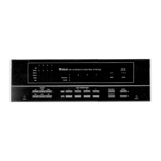
These pushbuttons turn an area ON or OFF. When any of these pushbuttons are turned ON, the CR10 will turn on and the front panel will be illuminated, if a PC-1 is connected in the system, the AC power for the specified area amplifier will also turn on. -
Page 10: Hr10 Hand Held Remote Controller Pushbuttons
9. MUTE AREA 1 CR10 FRONT Press this button to mute all sound in area 1. A CR10 front panel LED will turn on to in- PANEL dicate muting. Press again to restore sound. PUSHBUTTONS 10. SYSTEM OFF AND DISPLAYS This pushbutton turns the entire CR10 system off. -
Page 11: Rear Panel Connections
This connector can also be used to add a full featured Mclntosh Remote Control Center such as a C38 or C39 to a CR10 system. When used with a matching Mclntosh power amplifier these components can be used as the main area system with its own dedicated loudspeakers. - Page 12 J. POWER CONTROL REAR PANEL Connector to add the cable from a Mclntosh PC-1 Power Controller. This turns on AC CONNECTIONS power to each remote area power amplifier, when the area is turned on. It also provides swit- ched AC power for five audio accessories, two video accessories and 3 unswitched outlets. The unswitched outlets provide AC power as long as the PC-1 power cable is connected to a live AC wall outlet.
-
Page 13: An Example Of How To Program And Operatea Cr10 Remote System
CR10 system. When the entire CR10 system is turned off, all previous programming is canceled. You can turn the system on at the CR10 location, or in any remote area. When the CR10 turns back on, the TUNER is automatically selected at a -50dB volume level. -
Page 14: Your Remote System Configuration
YOUR REMOTE SYSTEM CONFIGURATION... - Page 15 YOUR REMOTE SYSTEM CONFIGURATION...
-
Page 16: Specifications
FREQUENCY RESPONSE SPECIFICATIONS + 0, -0.5dB from 20Hz to 20,000Hz RATED OUTPUT VOLTAGE 2.5 volts SENSITIVITY All Inputs, 0.25 volts for 2.5 volts rated output TOTAL HARMONIC DISTORTION 0.004% maximum from 20Hz to 20,000Hz at rated output BLOCK DIAGRAM... - Page 17 The letters correspond to the paragraphs on pages 8 and 9...
- Page 18 The letters and numbers correspond to the paragraphs on pages 7 through 10...
- Page 20 04010100 BE022003...


Need help?
Do you have a question about the CR10 and is the answer not in the manual?
Questions and answers