Advertisement
- 1 About This Instruction Manual
- 2 Main Features
- 3 Name of Parts
- 4 What's Inside
- 5 Separately Sold Accessories
- 6 Installing/Disassembling Battery
- 7 Battery Level Indication
- 8 Installing/Disassembling the Camera Flash
- 9 Installing/Disassembling SU-1
- 10 Power Management
- 11 Wi-Off Mode
- 12 Sender Mode
- 13 Receiver Mode
- 14 Other Functions
- 15 Wireless Settings
- 16 Menu
- 17 Wireless Flash Shooting (2.4G Wireless Transmission)
- 18 Wireless Sender/Receiver Settings
- 19 About the Sender Unit
- 20 Sender Unit's (Flash) ON/OFF
- 21 TTL: Fully Automatic Wireless Flash Shooting
- 22 M: Wireless Stroboscopic Flash Shooting with Manual Flash
- 23 Wireless Stroboscopic Flash Shooting with Multi Flash
- 24 Other Applications
- 25 Control with the Camera's Menu
- 26 Protection Function
- 27 The Reason & Solution of Not Triggering in Godox 2.4G Wireless
- 28 Technical Data
- 29 Troubleshooting
- 30 Firmware Upgrade
- 31 Compatible Camera Models
- 32 Maintenance and Service Support Information
- 33 Important Safety Instructions
- 34 Documents / Resources
About This Instruction Manual
This manual is based on the assumption that both the camera and camera flash's power switches are turned on.
The following alert symbols are used in this manual:
The caution symbol  indicates a warning to prevent shooting problem.
The note symbol  gives supplemental information.
Main Features
TTL li-ion round head camera flash V100 C is perfect for TTL auto flash with its excellent compatibility, you can enjoy unprecedented shooting convenience even with frequent changes in lighting conditions.
Intuitive Touch Screen: The 2.3" ultra-high definition touch screen is sensitive and intuitive to achieve clear and convenient operations
Dual Operation Options: Traditional physical buttons and select dial, or modernized touch screen control, are both available.
Round Flash Head: Well-crafted round flash head offers round, soft and even light effects.
Powerful Flash Functions: 100Ws flash power at 1/1 step in M mode, 81 steps adjustable from 1/1 to 1/256 or from 2.0 to 10, suitable for full range of shooting needs.
Fine-adjustable Modeling Lamp: Built-in 2W LED modeling lamp with adjustable brightness from 1 to 10 caters the lighting needs of different scenes.
Effective Power Supply: 7.2V 2980mAh lithium battery provides merely 1.7s recycle time and up to 400 flashes at full power output.
TTL Compatibility: Perfect compatible with TTL technology to achieve auto flash control, competent with both sender and receiver units.
Wireless Control Ability: 2.4G wireless sending and receiving module allows for easy remote control of flashes.
Abundant Accessories Choices: Optional power box PB960 enables quicker recycle time of approx. 0.8s, detachable sub flash SU-1 brings better filling light effects.
Fully-upgraded Functions: Support M (manual) flash, Multi flash, high-speed sync, second-curtain sync, FEC, etc.
Stable Continuous Shooting: The output brightness and CCT remain consistent, and the light is evenly distributed in high-speed continuous shooting.
Continuous Firmware Upgrade: Godox is committed to regularly updating its flash software to maintain the optimal compatibility with the original camera system.
Note: The power box PB960 is sold separately.
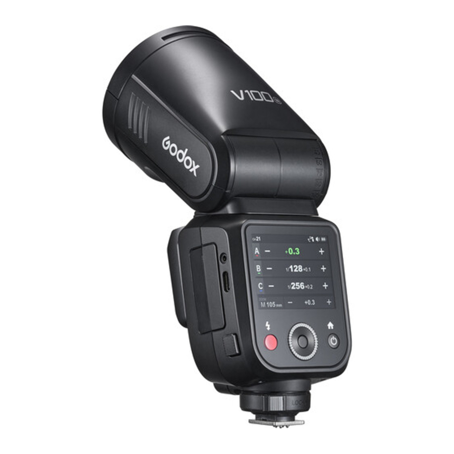
Name of Parts
Body


- Flash Head
- LED Modeling Lamp
- External Flash Interface
- Wireless Sensor
- Focus Assist Beam
- External Power Box Port
- Bounce Angle Scale
- Battery Charging Indicator (red in charging, green in fully charged)
- USB Type-C Charging Port
- Lithium Battery
- Touch Screen
- Power Switch Button (Short press once to enter mode/ return interface, press twice to enter other functions interface)
- Hot Shoe
- Hot Shoe Fixing Buckle
- Test Button/Recycle Indicator
- Select Dial
- Set Button (Short press to select or confirm)
- Sync Cord Jack
- USB-C Firmware Upgrade Port
Detachable Sub Flash SU-1

- Flash Tube
- Detaching Pusher
2.3 " LCD Panel

What's Inside

Separately Sold Accessories
The product can be used in combination with the following accessories sold separately, so as to achieve the best photography effects:


Note: Please purchase the correct accessories according to your flash models.
Installing/Disassembling Battery
Disassembling the battery: Press and hold the battery remove button, then push the battery out of the battery compartment.

Installing the battery: Insert the battery into the battery compartment in the direction as referred below until it's firmly locked.

Battery Level Indication
Make sure the battery pack is securely loaded in the flash. Check the battery level indication on the LCD panel to see the remaining battery level.
| Battery Level Indication | Meaning |
| 3 grids | Full |
| 2 grids | Middle |
| 1 grid | Low |
| Blank grid | Lower battery, please recharge it. |
| No battery alert blinking | The battery level is going to be used out, and the flash is not functional in this status. Note: Please recharge the battery as soon as possible (within 10 days). Then, the battery can be used or be placed for long period. |
Installing/Disassembling the Camera Flash
Installing the camera flash: Rotate the hot shoe fixing buckle and rotate it to the left, insert the camera flash into the camera's hot shoe. Then rotate it to the right until it locks up.

Disassembling the camera flash: Press and rotate the hot shoe fixing buckle to the left until it is loosened, then take off the camera flash.

Installing/Disassembling SU-1
Installing: Align the detachable sub flash SU-1 with the external flash interface of V100 C and insert it parallelly, then press it down, a "click" sound means it's properly installed. | Disassembling: Push the detaching pusher on SU-1 and pull it up at the same time to detach it. |
Note: Please turn off V100 C before installing and disassembling SU-1. Do not insert in or pull out SU-1 when V100 C is in power on status or working, otherwise malfunctions may occur.
Power Management

Power On: Long press the power switch button until the < SET > icon appears on the panel, then slide the screen or rotate the select dial in the direction showed on the panel to turn it on.
Standby: Setting as wi-off/sender mode when the standby function is on, the flash will enter standby mode automatically after a certain period (approx. 90 seconds) of idle use. Press the camera shutter halfway or press any button will wake up the flash unit.
Auto Off:
- Setting as wi-off/sender mode when the auto off function is on (the auto off function is available only after the standby function is off), the flash will automatically shut down after 60 minutes (or 30 minutes, 90 minutes) of idle use.
- Setting as receiver mode and turning on the auto off function (the auto off function is available no matter the standby function is on or off), the flash will automatically shut down after 60 minutes (or 30 minutes, 90 minutes) of idle use. The auto off function can be turned off when using offcamera as a receiver unit.
Wi-Off Mode
Touch Screen: Slide the screen from the left to the right to make the mode interface appears, click the "Wi-Off" icon to enter Wi-Off mode.

Buttons and Select Dial: Press the power switch button to make the mode interface appears, rotate the select dial and press the set button to choose and enter Wi-Off mode.

M: Manual Flash
The flash output is adjustable from 1/1 to 1/256 or from 2.0 to 10 with 0.1 increment each step. To obtain a correct flash exposure, use a hand-held flash meter to determine the required flash output.
Touch Screen: Click the "MODE" icon to switch to M mode, press the – or + icon to adjust the power with ±0.1 increment each step, or directly pull the progress bar to achieve quick adjustment.

Buttons and Select Dial: Rotate the select dial and press the set button to choose "MODE" icon, then rotate and press again to choose "M". Rotate up to choose the power value, then rotate and press again to adjust power with 0.1 increment each step, quick adjustment is also available by fast rotation.
S1 Photocell Unit Setting
In M manual flash mode, this flash can function as an optic S1 secondary flash with optic sensor. With this function, the flash will fire synchronously when the main flash fires, the same effect as that by the use of wireless triggers. This helps create multiple lighting effects.
S2 Photocell Unit Setting
In M manual flash mode, this flash can also function as an optic S2 secondary flash with optic sensor. This is useful when cameras have preflash function. With this function, the flash will ignore a single "pre-flash" from the main flash and will only fire in response to the second, actual flash from the main flash.
- S1 and S2 Photocell triggering is only available in M manual flash mode.
- Enter menu setting to switch between S1/S2 Photocell or turn off this function.
TTL: TTL Auto Flash
In TTL mode, the camera's metering system detects the flash reflected from the subject and automatically adjusts the flash output so that the subject and background are evenly exposed.
Touch Screen: Click the "MODE" icon to switch to TTL mode, press the – or + icon to adjust the FEC amount among ±3 with ±1/3 increment each step, or directly pull the progress bar to achieve quick adjustment.

Buttons and Select Dial: Rotate the select dial and press the set button to choose "MODE" icon, then rotate and press again to choose "TTL". Rotate up to choose the FEC amount, then rotate and press again to adjust the FEC amount among ±3 with ±1/3 increment each step, quick adjustment is also available by fast rotation.
- Press the camera shutter halfway to focus. The effective flash range will be displayed in the LCD panel.
- When the shutter is fully pressed, the flash will fire a pre-flash that the camera will use to calculate exposure and flash output the instant before the photo is taken.
ZOOM: Setting the Flash Coverage
The flash coverage can be set automatically or manually. In auto zoom mode, the focal length changes in response to the camera's zoom lens to provide optimal flash results.
Auto Zoom Mode: A-mm, and the flash coverage will be set automatically.
Manual Zoom Mode: 28 mm, 35 mm, 50 mm, 70 mm, 80 mm, 105mm.
Touch Screen: Click the "ZOOM" icon to switch between auto zoom(A--mm) mode or manual zoom mode.

Buttons and Select Dial: Rotate the select dial and press the set button to choose "ZOOM" icon, then rotate and press again to choose the needed zoom mode.
If you set the flash coverage manually, make sure it covers the lens focal length so that the picture will not have a dark periphery.
SUB: Detachable Sub Flash SU-1
With detachable sub flash SU-1 attached to the external flash interface, better filling light effects can be achieved in M (manual) flash/TTL auto flash mode, this is helpful for portrait shooting.
Installation: Mount SU-1 directly to the external flash interface of V100 C, a "click" sound means it's properly installed.
Flash Power Range: From 1/128 to 1/1 or from 3.0 to 10 in 8 steps, with +1/3 increment each step.
Touch Screen: Click the "SUB" icon to adjust its flash power by pressing "-" or "+" icon or sliding the progress bar. Turn on or off the sub flash by clicking the on/off icon down the screen.
Buttons and Select Dial: Rotate the select dial and press the set button to choose "SUB" icon, then rotate and press it again to adjust its flash power or turn it on/off.
- SU-1 is not useable in sender or receiver mode.
- The flash head need to be uplifted in order to use SU-1 properly.
- External flash do not support HSS.
Sender Mode
Touch Screen: Slide the screen from the left to the right to make the mode interface appears, click the "Sender" icon to enter sender mode, slide upward can check more groups.

Buttons and Select Dial: Press the power switch button to make the mode interface appears, rotate the select dial and press the set button to choose and enter sender mode, rotate the select dial can check more groups.

The wireless is turned on by default in sender mode.
Group
Five groups: A, B, C, D, E
M: Manual Flash—Flash Power
Touch Screen: Press and hold the group box to switch among M (manual) flash, TTL auto flash and OFF. If the value inside is from 1/256 to 1/1 or from 2.0 to 10, this group is in M (manual) flash mode and the value inside is the flash power. The flash power is adjustable by clicking the – or + icon, or quickly adjustable by pulling the progress bar.
Buttons and Select Dial: Rotate the select dial and press the set button to choose and enter a certain group, press and hold the set button to switch among M (manual) flash, TTL auto flash and OFF. If the value inside is between 1/256 to 1/1 or from 2.0 to 10, this group is in M (manual) flash mode and the value inside is the flash power. The flash power is adjustable by rotating the select dial, then press the set button to exit.
TTL Auto Flash—Flash Exposure Compensation Amount
Touch Screen: Press and hold the group box to switch among M (manual) flash, TTL auto flash and OFF. If the value inside is from -3.0 to +3.0, this group is in TTL auto flash mode and the value inside is the flash compensation amount. The flash compensation amount is adjustable by clicking the – or + icon, or quickly adjustable by pulling the progress bar.
Buttons and Select Dial: Rotate the select dial and press the set button to choose and enter a certain group, press and hold the set button to switch among M (manual) flash, TTL auto flash and OFF. If the value inside is between -3.0 to +3.0, this group is in TTL auto flash mode and the value inside is the flash compensation amount. The flash compensation amount is adjustable by rotating the select dial, then press the set button to exit.
Adjust the Paremeters Uniformly
Touch Screen: Click the – or + icon can increase or decrease the flash power or FEC amount uniformly.
Buttons and Select Dial: Rotate the select dial and press the set button to choose and enter a certain group, press the set button to enter uniform adjustment and rotate the select dial to increase or decrease the flash power or FEC amount uniformly, then press the set button to exit.
ZOOM: Setting the Flash Coverage
You can choose auto zoom mode or manual zoom mode (28mm-105mm). The details of which please refer to the ZOOM section in the Wi-Off mode above.
Receiver Mode
Touch Screen: Slide the screen from the left to the right to make the mode interface appears, click the "Receiver" icon to enter receiver mode.

Buttons and Select Dial: Press the power switch button to make the mode interface appears, rotate the select dial and press the set button to choose and enter receiver mode.
The wireless is turned on by default in receiver mode.
Group
Five receiver groups: A, B, C, D, E
Touch Screen: Click the group icon to switch groups.
Buttons and Select Dial: Rotate the select dial to choose the group icon, then press the set button to enter group settings and rotate the select dial to switch groups, finally press the set button again to exit.
TTL: TTL Auto Flash
Touch Screen: Click the "MODE" icon to switch to TTL mode.
Buttons and Select Dial: Rotate the select dial to choose the "MODE" icon, then press the set button to enter MODE settings and rotate the select dial to switch to TTL mode, finally press the set button again to exit.
The details of which please refer to the section Wi-Off mode → TTL auto flash above.
M: Manual Flash
Touch Screen: Click the "MODE" icon to switch to M mode.
Buttons and Select Dial: Rotate the select dial to choose the "MODE" icon, then press the set button to enter MODE settings and rotate the select dial to switch to M mode, finally press the set button again to exit.
The details of which please refer to the section Wi-Off mode → M: manual flash above.
Flash Power Settings
The flash power adjustable from 1/256 to 1/1 or from 2.0 to 10 when choosing M (flash) mode.
Touch Screen: The flash power is adjustable by clicking the – or + icon, or quickly adjustable by pulling the progress bar.
Buttons and Select Dial: Rotate the select dial to choose the flash power box, press the set button to enter flash power settings and rotate the select dial to adjust, finally press the set button again to exit.
ZOOM: Setting the Flash Coverage
You can choose auto zoom mode or manual zoom mode (28mm-105mm). The details of which please refer to the ZOOM section in the Wi-Off mode above.
Other Functions
Touch Screen: When in Wi-Off/Sender/ Receiver mode, slide the screen down to make other functions appear, slide up to return to the main interface.

Buttons and Select Dial: When in WiOff/Sender/Receiver mode, short press the power switch button twice to make other functions appear, press it again to return to the main interface.
Sync Mode
 High-speed Sync
High speed sync (FP flash) enables the flash to synchronize with all camera shutter speeds. This is convenient when you want to use aperture priority for fill-flash portraits.
![]() Second-curtain Sync
Second-curtain Sync
With a slow shutter speed and second-curtain sync, you can create a light train following the subject. The flash fires right before the shutter closes.
Touch Screen: Click the "SYNC" icon to switch sync mode.
Buttons and Select Dial: Rotate the select dial to choose "SYNC" icon, then press the set button to switch sync mode.
![]() Auto Focus Assist Beam
Auto Focus Assist Beam
In poorly-lit or low-contrast shooting environments, the built-in auto focus assist beam will automatically light on to make it easier for autofocus. The beam will light up only when autofocus is difficult and get out as soon as the autofocus becomes correct.
Touch Screen: Click the "AF" icon to turn on or off the auto focus assist beam.
Buttons and Select Dial: Rotate the select dial to choose "AF" icon, then press the set button to turn on or off the auto focus assist beam.
| Position | Effective Range |
| Center | 0.6~10m / 2.0~32.8 feet |
| Periphery | 0.6~5m / 2.0~16.4 feet |
If you find the auto focus assist beam does not light up, this is because the camera has got a correct autofocus.
 Beep
Beep
The flash will fire with a prompt tone if the beep is turned on.
Touch Screen: Click the "Beep" icon to turn on or off the beep.
Buttons and Select Dial: Rotate the select dial to choose "Beep" icon, then press the set button to turn on or off the beep.
 Modeling Lamp
Touch Screen: Click the "Model" icon to turn on or off the modeling lamp. The brightness of it is adjustable from 1 to 10 by pulling the progress bar down when it's turned on.
Buttons and Select Dial: Rotate the select dial to choose "Model" icon, then press the set button turn on or off the modeling lamp. When the modeling lamp is on, its brightness is adjustable from 1 to 10 by rotating the select dial and pressing the set button after selecting the progress bar down, then press the set button again to exit.
 Screen Lock
Touch Screen: Click the "Lock" icon to turn on the screen lock, press and hold for 2s to unlock.
Buttons and Select Dial: Rotate the select dial to choose "Lock" icon, then press the set button to turn on the screen lock, press and hold for 2s to unlock.
 Multi Flash
With slow shutter speed in multi flash mode, a rapid series of flashes is fired. It can be used to capture multiple images of a moving subject in a single photograph.
You can set the flash frequency (number of flashes per sec. expressed as Hz), the number of flashes, and the flash output.
Flash output range: 1/256-1/4 or 2.0-8.0.
Number of flashes: 1-100
Flash frequency: 1-100
ZOOM range: auto zoom (A—mm), manual zoom (M 28mm, M 35 mm, M50 mm, M70 mm, M 80 mm, M 105mm)
Touch Screen: Click the "Multi" icon to turn on or off the multi flash. When the multi flash is turned on, slide the screen up can adjust the parameters. Slide the number in front of "Times" can adjust the number of flashes, slide number in front of "Hz" can adjust the flash frequency, click the – or + icon can adjust the flash power, press the "ZOOM" icon down to enter the ZOOM setting interface and choose auto zoom or manual zoom, then adjust the ZOOM value. Finally press the return icon to back to the multi flash interface.
Buttons and Select Dial: Rotate the select dial to choose "Multi" icon, then press the set button to turn on or off the multi flash. When the multi flash is turned on, press the power switch button to make the parameters interface appears, then the flash power, number of flashes, flash frequency and ZOOM value are all adjustable by rotating the select dial, finally press the set button again to exit.
Calculating the Shutter Speed
During multi flash, the shutter remains open until the firing stops. Use the formula below to calculate the shutter speed and set it with the camera.
Number of Flashes ÷ Flash Frequency = Shutter Speed
For example, if the number of flashes is 10 and the flash frequency is 5Hz, the shutter speed should be at least 2 seconds.
To avoid overheating and deteriorating the flash head, do not use multi flash more than 10 times in succession. After 10 times, allow the camera flash to rest for at least 15 minutes. If you try to use the multi flash more than 10 times in succession, the firing might stop automatically to protect the flash head. If this happens, allow at least 15 minutes' rest for the camera flash.
- Multi flash is most effective with a highly reflective subject against a dark background.
- Using a tripod and TTL flash trigger XPROII is recommended.
- A flash output of 1/1 and 1/2 cannot be set for multi flash.
- Multi flash can also be used with "buLb" mode.
- Multi flash mode cannot be set in high-speed sync mode.
- Please turn off the multi flash when not using, otherwise TTL flash and M flash are not available.
Maximum Time of Consecutive Flashes

Wireless Settings

Touch Screen: Slide the screen from the left to the right to make the mode interface appears, click the "Wireless" icon to enter wireless mode. Then slide from the left to the right to return to the main interface.
Buttons and Select Dial: Press the power switch button to make the mode interface appears, rotate the select dial and press the set button to choose and enter wireless mode. Short press the power switch button to return to the main interface.
Scan the Spare Channel
You can scan the spare channel to avoid the interference of using the same channel by others.
Touch Screen: Click the "SCAN" icon to start scanning, and the 8 spare channels will be displayed, click your desired channel.
Buttons and Select Dial: Rotate the select dial to choose "SCAN" icon, then press the set button to start scanning, and the 8 spare channels will be displayed, rotate the select dial and press the set button to choose your desired channel.
Channel Settings
If there are other wireless flash systems nearby, you can change the wireless channels to prevent signal interference. The wireless channels (0132) of the sender unit and the receiver unit(s) must be set to the same.
Touch Screen: Slide the "Channel" box to choose your desired channel.
Buttons and Select Dial: Rotate the select dial to choose "Channel" box, then press the set button to enter channel settings, rotate the select dial and press the set button to choose your desired channel, finally press the set button to exit.
ID Settings
Change the wireless ID to avoid interference for it can only be triggered after the wireless IDs (OFF/01-99) of the sender unit and the receiver unit are set to the same.
Touch Screen: Slide the "ID" box to turn off the ID, or choose your desired ID.
Buttons and Select Dial: Rotate the select dial to choose "ID" box, then press the set button to enter ID settings, rotate the select dial and press the set button to choose your desired ID, finally press the set button to exit.
Wireless Sync
 The wireless sync function helps the sender and receiver to quickly set the same channel and ID.
Receiver Wireless Sync
Preconditions:
- Set V100 C to sender mode and the "Sender" icon on the panel is yellow.
- Assume retro camera flash Lux Master as the receiver.
Touch Screen: Click the "SYNC" icon on both V100 C and Lux Master.
Buttons and Select Dial: Rotate the select dial on V100 C to choose "SYNC" icon, then press the set button. Rotate the select dial on Lux Master to choose "SYNC" icon, then press the SET button.
Sender Wireless Sync
Preconditions:
- Set V100 C to receiver mode and the "Receiver" icon on the panel is yellow.
- Assume flash trigger X3 C as the sender.
Touch Screen: Click the "SYNC" icon on both V100 C and X3 C.
Buttons and Select Dial: Rotate the select dial on V100 C to choose "SYNC" icon, then press the set button. Rotate the select dial on X3 C to choose "SYNC" icon, then press the select dial.
When the sender unit and receiver unit are both V100 C, wireless sync is also available.
Menu
Touch Screen: Slide the screen from the left to the right to make the mode interface appears, click the "Menu" icon to enter the menu interface. Then slide from the left to the right to return to the main interface.
Buttons and Select Dial: Press the power switch button to make the mode interface appears, rotate the select dial and press the set button to choose and enter the menu interface. Short press the power switch button to return to the main interface.
| Icon | Function | Options | Description |
 | Sender Flash | Off | Sender flash off |
| On | Sender flash on | ||
 | Power Type | 1/256 | Minimum power step is 1/256 |
| 2.0 | Minimum power step is 2.0 | ||
 | Photocell | S1 | Only available in M (manual) flash mode, the flash will fire synchronously when the main flash fires. |
| S2 | Only available in M (manual) flash mode, the flash will ignore a single "pre-flash" from the main flash and will only fire in response to the second, actual flash from the main flash. | ||
 | m/ft | m | Meter |
| ft | Feet | ||
 | Standby | On | Automatically standby after the set time (90 seconds) of idle use. |
| Off | Do not automatically standby after the set time (90 seconds) of idle use. | ||
 | Auto Off | Off | Turn off auto power off function |
| 30 min |
| ||
| 60 min |
| ||
| 90 min |
| ||
 | Model | Continue | The modeling lamp is constant on when flashing. |
| Interrupt | The modeling lamp automatically turns off when flashing. | ||
 | Screen | / | Screen brightness is steplessly adjustable. |
| 30 sec | Screen standby after 30 seconds of idle use. | ||
| 1 min | Screen standby after 1 minute of idle use. | ||
| 2 min | Screen standby after 2 minutes of idle use. | ||
| 3 min | Screen standby after 3 minutes of idle use. | ||
 | Language | Simplified Chinese | Simplified Chinese system |
| English | English system | ||
 | Factory Reset | Cancel | Cancel factory reset |
| Apply | Factory reset | ||
 | Device Info | / | Display the device model and firmware version |
Wireless Flash Shooting (2.4G Wireless Transmission)
This section explains wireless sending/receiving flash shooting.
The V100 C attached to the camera is referred as the sender unit, while a V100 C that is wirelessly controlled is referred as the receiver unit.
You can also wirelessly control the V100 C set as the receiver unit with the TTL flash trigger XPROII (sold separately). For details on setting the flash trigger functions, see the its instruction manual.
When the camera's shooting mode is set to a fully automatic mode or an image zone mode, the operations in this section are not available. Please set the camera's shooting mode to Fv/P/Tv/Av/M/B.
Using a flash with a radio transmission wireless shooting function make it easy to shoot with advanced wireless multiple flash shooting, in the same way as TTL auto flash shooting.
As long as the channel, group, ID, and other relevant wireless settings of the sender and receiver units are set to the same, the settings on the V100 C (sender unit) will be automatically applied to the wirelessly controlled V100 C (receiver unit). Therefore, there is no need to operate the receiver unit during shooting.
Positioning and Operation Range
- Auto Flash Shooting with One Receiver Unit

- Auto Flash Shooting with Multiple Receiver Groups
You can divide the receiver units into two or three groups and perform TTL auto flash while changing the flash ratio (flash output ratio).


- Before shooting, perform a test flash and test shooting.
- The transmission distance might be shorter depending on the conditions such as positioning of receiver units, the surrounding environment and whether conditions.
- Shooting with a Different Flash Mode Set for Each Group


Wireless Sender/Receiver Settings
Set as a Sender Unit
Touch Screen: Slide the screen from the left to the right to make the mode interface appears, click the "Sender" icon to enter sender mode, slide from the left to the right to return to the main interface.
Buttons and Select Dial: Press the power switch button to make the mode interface appears, rotate the select dial and press the set button to choose and enter sender mode. Short press the power switch button to return to the main interface.
Set as a Receiver Unit
Touch Screen: Slide the screen from the left to the right to make the mode interface appears, click the "Receiver" icon to enter receiver mode, slide from the left to the right to return to the main interface.
Buttons and Select Dial: Press the power switch button to make the mode interface appears, rotate the select dial and press the set button to choose and enter receiver mode. Short press the power switch button to return to the main interface.
About the Sender Unit
Use two or more sender units. By preparing several cameras that with sender units attached, cameras can be changed in shooting while keeping the same lighting source (receiver unit).
Sender Unit's (Flash) ON/OFF
You can set whether the sender unit flash that sends wireless signal flashes or not, and when the sender unit flash setting is on, the flash fires as a flash A group.
Touch Screen: Slide the screen from the left to the right to make the mode interface appears, click the "Menu" icon to enter menu interface, choose "Sender Flash" icon and click to turn on or off the sender flash.
Buttons and Select Dial: Press the power switch button to make the mode interface appears, rotate the select dial and press the set button to enter menu interface and choose "Sender Flash", then rotate the select dial and press the set button to turn on or off the sender flash. Short press the power switch button to return to the main interface.
Even if the sender unit flash firing is off, it still sends wireless flash signals.
TTL: Fully Automatic Wireless Flash Shooting
The below instructions are described in touch screen operation, you can also use buttons and select dial.
- Using Automatic Wireless Flash with a Single Receiver Unit
- Sender Unit Setting

Click the "Sender" icon on the panel, then the V100 C attached to the camera is set as the sender unit. - Receiver Unit Setting

Click the "Receiver" icon on the panel, then the V100 C wirelessly controlled is set as the receiver unit.
X2T-C can also be set as sender unit. X2T-C can control V100 C's ZOOM value when the ZOOM is adjusted to auto (A) mode. - Check the Communication Channel /ID

Set the wireless channels and IDs of sender unit and receiver unit to the same. For example, if the sender unit channel is set to 1, then the receiver unit channel needs to be 1 as well. You can also use the wireless sync function to set the channels and ID to the same quickly.


- Position the Camera and Flashes

The transmission distance of the sender unit and receiver unit is about 100m. - Set the Flash Mode to <TTL>

Click the "Sender" icon on the panel to enter sender mode. Press and hold the group "A/B/C/D/E" box to switch to TTL auto flash compensation amount. Please set the sender unit's flash to ON in order to make the sender unit fire flashes. - Check Whether the Flash is Ready

Check whether the sender unit's flash ready indicator is lightened. - Check the Flash Operation

Press the sender unit's test button <![]() >. Then, the receiver unit will fire. If not, adjust the distance from the sender unit.
>. Then, the receiver unit will fire. If not, adjust the distance from the sender unit.


 >. Then, the receiver unit will fire. If not, adjust the distance from the sender unit.
- Using Automatic Wireless Flash with Multiple Receiver Units

When stronger flash output or more convenient lighting operation is needed, increase the number of receiver units and set it as a single receiver unit.
To add receiver units, use the same steps as setting "using automatic wireless flash with a single receiver unit". Any flash group can be set (A/B/ C/D/E).
When the number of receiver units is increased or the sender unit flash firing is ON, automatic control is implemented to make all groups of flashes fire the same flash output and ensure the total flash output is up to standard exposure.

- Press the depth-of-field preview button on the camera to fire a modeling flash.
- If the receiver unit's auto power off function is on, press the sender unit's test button to power it on. Please note that test firing is unavailable during the camera's regular metering time.
- The effective time of receiver unit's auto power off is changeable between 30min or 90min in the menu settings.
M: Wireless Stroboscopic Flash Shooting with Manual Flash
Using wireless (multiple flash) shooting with manual flash, you can shoot with a different flash output setting for each receiver unit (flash group) while setting all parameters on the sender unit.
- Click the "Sender" icon on the panel, then the V100 C attached to the camera is set as the sender unit.
Click the "Sender" icon on the panel to enter sender mode. Press and hold the group "A/B/C/D/E" box to switch to M manual flash power. - Set the flash output of each flash group
Click the – or + icon to adjust the flash output of each flash group. - Set the wireless channels and IDs of sender unit and receiver unit to the same.
For example, if the sender unit channel is set to 1, then the receiver unit channel needs to be 1 as well.
You can also use the wireless sync function to set the channels and ID to the same quickly. - Take Picture
Each receiver unit fires at the set flash ratio.
Wireless Stroboscopic Flash Shooting with Multi Flash

- Set the Sender Unit to Wireless Multi Flash
Click the "Sender" icon onto the sender unit' LCD panel to enter sender settings. Slide the screen down to make the "Multi" icon appears and click to turn it on, then slide up to make the wireless multi flash parameters appear. - Set the Flash Output, Number of Flashes and Flash Frequency of the Wireless Multi Flash
Click the – or + icon can adjust the flash output, slide the number in front of "Times" can adjust the number of flashes, slide number in front of "Hz" can adjust the flash frequency. - Set the Receiver Unit
Click the "Receiver" icon onto the sender unit' LCD panel to enter receiver settings. - Set the Wireless Channels and IDs of Sender Unit and Receiver Unit to the Same
For example, if the sender unit channel is set to 1, then the receiver unit channel needs to be 1 as well. - Turn On/Off the Wireless Multi Flash of Receiver Unit Group
The wireless multi flash of receiver unit A/B/C/D/E can be turned on or off directly on the sender unit.
The parameters of receiver unit can be directly set on the sender unit on the condition that channels and IDs of them are set to the same.
Other Applications
Sync Triggering
The sync cord jack is a Φ2.5mm plug. Insert a trigger plug here and the flash will be fired synchronously with the camera shutter.
Modeling Flash
If the camera has a depth-of-field preview button, pressing it will fire the flash continuously for 1 second. This is called modeling flash. It enables you to see the shadow effects on the subject and the lighting balance. You can fire the modeling flash during wireless or normal flash shooting.
Note:
- To avoid overheating and deteriorating the flash head, do not fire the modeling flash for more than 10 consecutive times. If you fire the modeling flash 10 consecutive times, allow at least 10 minutes' break for the camera flash.
- The modeling flash cannot be fired with the Canon EOS 300 and Type-B cameras.
Bounce Flash
By pointing the flash head toward a wall or ceiling, the flash will bounce off the surface before illuminating the subject. This can soften shadows behind the subject for a more natural-looking shot. This is called bounce flash.

To set the bounce direction, hold the flash head and turn it to a satisfying angle.
Note:
- If the wall or ceiling is too far away, the bounced flash might be too weak and result in underexposure.
- The wall or ceiling should be a plain, white color for high reflectance. If the bounce surface is not white, a color cast may appear in the picture.
Low Battery Warning
If the battery power is low, the < > icon will turn red. Please replace or charge the battery immediately.

Control with the Camera's Menu
If the camera flash is attached to an EOS camera which has a camera control function, the flash can be controlled using the camera's menu screen.
The functions that can be set are as follows. The available settings vary depending on the flash mode, wireless flash function settings, and other conditions.
| Function | |
| Flash Firing | On/Off |
| E-TTL Balance | Ambience priority/Standard/Flash priority |
| TTL Metering | Evaluative (Face priority) / Evaluative / Average |
| Continuous Flash Control | E-TTL shooting every time / E-TTL shooting for the first time |
| Flash synchronization speed in aperture-priority mode | |
| Flash Mode | TTL flash metering (auto flash) /manual flash/multi flash (stroboscopic) |
| Wireless Functions | Wireless flash: Off/Radio transmission |
| Zoom (Flash Coverage) | |
| Shutter Sync | First-curtain Sync/Second-curtain Sync /High-speed Sync |
| Flash Exposure Compensation | |
Setting Camera Flash Functions
- Select <Flash control> or <External Speedlite control>.

- Select <Flash function settings> or <External func. setting >.

- The setting screen and items displayed vary depending on the camera.


- To clear all custom function settings, you can enter the [Clear settings] in step 2 and select [Clear all Speedlite C.Fn's] or [Clear ext. flash C.Fn set.].
- If flash exposure compensation has already been set with the camera flash, flash exposure compensation cannot be set with the camera. To set it with the camera, the camera flash's flash exposure compensation must be set to zero.
- If any flash custom functions and flash settings other than flash exposure compensation have been set by both the camera and the flash, the latest settings will take effect.
Protection Function
Over-Temperature Protection
- To avoid overheating and deteriorating the flash head, do not fire more than 70 continuous flashes in fast succession at 1/1 full power. After 70 continuous flashes, allow a rest time of at least 10 minutes.
- If you fire more than 70 continuous flashes and then fi re more flashes in short intervals, the inner over-temperature protection function may be activated and make the recycle time over 10 seconds. If this occurs, allow a rest time of about 10 minutes, and the flash unit will then return to normal.
- When the over-temperature protection is started, < > is shown on the LCD display.
Number of flashes that will activate over-temperature protection:

Number of flashes that will activate over-temperature protection in HSS mode:
| Power Output Level | Number of Flashes |
| 1/1 | 60 |
| 1/2 (+0.1~+0.9) | 70 |
| 1/4(+0.1~+0.9) | 100 |
| 1/8(+0.1~+0.9) | |
| 1/16(+0.1~+0.9) | |
| 1/32(+0.1~+0.9) | |
| 1/64(+0.1~+0.9) | |
| 1/128(+0.1~+0.9) | |
| 1/256(+0.1~+0.9) |
Other Protections
The system provides real-time protection to secure the device and your safety. The following lists prompts for your reference:
| Display | Meaning |
| Error1 | A failure occurs on the recycling system so that the flash cannot fire. Please restart the flash unit. If the problem still exists, please send this product to a maintenance center. |
| Error3 | The voltage on two outlets of the flash tube is too high. Please send this product to a maintenance center. |
| Error5 | Abnormalities in the flash circuit. Please send this product to a maintenance center. |
| Error9 | There are some errors occurred during the upgrading process. Please using the correct firmware upgrade method. |
The Reason & Solution of Not Triggering in Godox 2.4G Wireless
- Disturbed by the 2.4G signal in outer environment (e.g. wireless base station, 2.4G wifi router, Bluetooth, etc.)
→ To adjust the channel CH setting on the flash trigger (add 10+ channels) and use the channel which is not disturbed. Or turn off the other 2.4G equipment in working.
- Please make sure that whether the flash has finished its recycle or caught up with the continuous shooting speed or not (the flash ready indicator is lightened) and the flash is not under the state of over-heat protection or other abnormal situations.
→ Please downgrade the flash power output. If the flash is in TTL mode, please try to change it to M mode (a pre-flash is needed in TTL mode).
- Whether the distance between the flash trigger and the flash is too close or not (<0.5m).
→ Please turn on the "close distance wireless mode":
X1 Series: Press and hold the triggering button then turn on the device until the indicator blinks twice.
Xpro and X2T Series: Set the C.Fn-DIST to 0-30m.
X3 Series: Set the triggering distance to 0-30m.
- Whether the flash trigger and the receiver end equipment are in the low battery states or not
→ Please replace the battery or charge it in time.
- The flash trigger's firmware is an older version
→ Please upgrade the firmware of the flash trigger referring to the instruction manual for specific firmware upgrades.
Technical Data
| Model | V100 C |
| Compatible Cameras | Canon cameras |
| Power (1/1 output) | 100Ws |
| Flash Coverage | Auto zoom (flash coverage is set automatically to match the lens focal length and image size) |
| Manual zoom(28 – 105mm) | |
| Swinging/tilting flash head (bounce flash): 0 to 330° horizontally and -7° to 120° vertically | |
| Flash Duration | 1/300s - 1/20000s |
| Exposure Control | |
| Exposure Control System | TTL auto flash and manual flash |
| Flash Exposure Compensation (FEC) | 3 steps with 1/3 increment each step |
| Sync Mode | High-speed sync (up to 1/8000 seconds), first-curtain sync, and second-curtain sync |
| Multi Flash | Provided (up to 100 times, 100Hz) |
| Wireless Flash (Radio 2.4G Transmission) | |
| Wireless Function | Sender, Receiver |
| Sender Groups | A,B,C,D,E |
| Controllable Receiver Groups | A,B,C,D,E |
| Transmission Range (approx.) | 100m |
| Channels | 32: 01~32 |
| ID | OFF/01~99 |
| Modeling Flash | Fired with camera's depth-of-field preview button |
| Auto Focus Assist Beam | |
| Effective Range (approx.) | Center: 0.6~10m / 2.0~32.8 feet Periphery: 0.6~5m/2.0~16.4 feet |
| LED Modeling Lamp | |
| Power | 2W |
| Color Temperature | 3300K±200K |
| Power Supply | |
| Built-in Lithium Battery | 7.2V/2980mAh |
| Recycle Time | Approx. 1.7 seconds. LED indicator will light up when the flash is ready. |
| Full Power Flashes | Approx. 400 |
| Power Saving | Provide standby and auto off functions |
| Sync Triggering Mode | Hot shoe, 2.5mm sync cord |
| Dimension | |
| W x H x D | 2.81"*2.99"*8.11" |
| Net Weight Without Battery | ≈ 496g |
| Net Weight With Battery | ≈ 616g |
Specifications and data may subject to changes without notice.
Troubleshooting
If there is a problem, refer to this troubleshooting guide.
The camera flash does not fire.
- The camera flash is not attached securely to the camera.
→Attach the camera's mounting foot securely to the camera.
- The electrical contacts of the camera flash and camera are dirty.
→Clean the contacts.
- <
![]() >or<
>or< ![]() > is not displayed in the view finder of camera.<>or<> is not displayed in the view finder of camera.
> is not displayed in the view finder of camera.<>or<> is not displayed in the view finder of camera.
→Wait until the flash is fully recycled and the flash ready indicator lights up.
→If the flash ready indicator lights up, but<  >or<
>or<  >is not displayed in the view finder, check whether this flash unit is securely attached to the camera hot shoe.
→If the flash ready indicator does not light up after a long wait, check whether the battery power is enough. If the battery power is low, <  > will appear red on the LCD panel. Please replace or charge the battery immediately.
The power turns off by itself.
- Setting as wi-off/sender mode when the standby function is on, the flash will enter sleep mode automatically after 90 seconds of idle use.
→Press the camera shutter halfway or press any button will wake up the flash unit.
- Setting as wi-off/sender mode when the standby function is off while the auto off function is on, the flash will automatically shut down after 60 minutes (or 30 minutes, 90 minutes) of idle use.
→Restart the flash unit.
- Setting as receiver mode when the auto off function is on, the flash will automatically shut down after 60 minutes (or 30 minutes, 90 minutes) of idle use.
→Restart the flash unit.
Auto zoom does not work.
- The camera flash is not attached securely to the camera.
→Attach the camera flash's mounting foot to the camera.
The flash exposure is underexposed or overexposed.
- You used high-speed sync.
→With high-speed sync, the effective flash range will be shorter. Make sure the subject is within the effective flash range displayed.
- You used manual flash mode.
→Set the flash mode to TTL or modify the flash output.
Photos have dark corners or only parts of the target subject are illuminated.
- The focal length of lens exceeds the flash coverage.
→Check the flash coverage you set. This flash unit has the flash coverage between 28 and 105mm, which fits medium-format cameras.
Firmware Upgrade
- This product supports firmware upgrade through the USB-C port, please use USB-C cable (sold separately).
- As the firmware upgrade needs the support of Godox G3 V1.1 software, please download and install the "Godox G3 V1.1 firmware upgrade software" before upgrading. Then, choose the related firmware file.
- Please refer to the latest electronic version of the instruction manual.
- The download website of firmware upgrade is:https://www.godox.com/firmware-flash/
Compatible Camera Models
V100 C unit can be used on the following Canon EOS series camera models:
1DX, 5D Mark II, 6D, 7D, 60D, 50D, 40D, 30D, 650D, 600D, 550D, 500D, 450D, 400D Digital, 1100D, 1000D, 5D Mark IV, 7D Mark II, 760D, 750D, 70D, 80D, 800D, 77D, M5, M3, M50, EOS R, 1500D, 3000D, RP
- This table only lists the tested camera models, not all cameras. For the compatibility of other camera models, a self-test is recommended.
- Rights to modify this table are retained.

Operating frequency: 2412.99MHz – 2464.49MHz
Maximum EIRP Power: 5.0dBm
Maintenance and Service Support Information
How to Get the Maintenance Service
If maintenance service is needed, you can directly contact the product distributor or authorized service institutions. You can also contact the Godox after-sale service call and we will offer you service. When applying for maintenance service, you should provide valid warranty card. If you cannot provide valid warranty card, we may offer you maintenance service once confirmed that the product or accessory is involved in the maintenance scope, but that shall not be considered as our obligation.
The warranty period and service types of products are implemented according to the following Product Maintenance Information:
| Product Type | Name | Maintenance Period(month) | Warranty Service Type |
| Parts | Circuit board | 12 | Customer sends the product to designated site |
| Battery | 3 | Customer sends the product to designated site | |
| Electrical parts e.g.battery charger, etc. | 12 | Customer sends the product to designated site | |
| Other Items | Flash tube, modeling lamp, lamp body, lamp cover, locking device, package, etc. | No | Without warranty |
Godox After-sale Service Call +86-755-29609320(8062)
Important Safety Instructions
This product is a professional photographic equipment, to be operated by professional personnel only.
All transport protective materials and packaging on the product must be removed before use.
The following basic safety precautions must be followed when using this product:
- Carefully read and fully understand the instruction manual before use and strictly follow the safety instructions. Failure to do so may result in death, serious injury, damage to the product, or other property damage.
- This product is a professional lighting fixture, children are prohibited from using it. Children must be closely supervised by adults when approaching the fixture, to prevent collisions with the fixture or unauthorized use that could cause personal injury.
- This is not an ordinary lighting fixture and must not be used for general illumination. Anyone with a history of eye damage or sensitivity should avoid using this fixture or looking directly at it.
- Extreme caution must be exercised when using it, do not touch hightemperature parts such as flash tubes to avoid burns.
- Do not point the flash directly at the eyes (especially baby's eyes) under any circumstances, as this could impair vision in a short time. Turn off immediately if discomfort occurs, stop using, and seek medical attention promptly.
- If the flash tube is damaged, stop using it immediately and contact the manufacturer, service agent, or qualified repair personnel for a replacement to prevent accidents.
- Stop using immediately if the product shell is cracked due to falling, squeezing, or strong impact, to avoid touching the internal electronic components and getting an electric shock.
- This device is not waterproof. Keep it dry and avoid immersing it in water or other liquids. It should be installed in a ventilated and dry location and avoid using in rainy, humid, dusty, or overheated environments. Do not place items above the device or allow liquids to flow into it to prevent danger.
- Do not disassemble without authorization. If the product malfunctions, it must be inspected and repaired by our company or authorized repair personnel.
- Before storing the device, make sure it is completely cooled.
- Do not place the device near alcohol, gasoline, or other flammable volatile solvents or gases such as methane and ethane.
- Do not use or store this device in potentially explosive environments.
- Maintain at least 1 meter distance between the lamp head and the user, other people, and heat-sensitive or flammable items during and after use.
- Do not use accessories not been approved by our company, as this may cause fire, electric shock or personal injury.
- Clean gently with a dry cloth. Do not use a wet cloth as it may damage the device.
- This instruction manual is based on rigorous testing. Changes in design and specifications are subject to change without notice. Check official website for latest instruction manual and product updates.
- This product is powered by lithium batteries, who have limited lifespans and will gradually lose their charging capacities, which is irreversible. As the battery ages, the product's battery life will decrease. The lifespan of lithium battery is estimated to be 2 to 3 years. Please regularly check the battery, and if the charging time significantly increases or the battery life significantly decreases, consider replacing the battery.
- This product is equipped with lithium batteries. The following are the storage recommendations: Charge the battery to about 50% before storage. Charge it to about 50% at least every six months. Removable batteries should be stored separately. The storage temperature should be between 0°C and 40°C.
- Precautions for using lithium batteries:
- Do not disassemble, crush, or puncture the battery;
- The battery is not waterproof, do not immerse it in fog or water;
- Avoid short-circuiting the battery contacts;
- Do not expose the battery to or put it into fire;
- Do not expose the battery to temperatures above 60°C;
- Keep out of reach of children;
- Protect the battery from excessive shock or vibration;
- Do not use a damaged battery;
- If the battery leaks, avoid contact with the leaking fluid;
- If the battery fluid comes into contact with your eyes, immediately rinse with water for at least 15 minutes. Lift your eyelids until there are no signs of fluid and seek medical attention promptly.
- Confirm and comply with all relevant local laws and regulations when handling any batteries.
- The warranty period for this device as a whole is one year. Consumables (such as batteries), adapters, power cords, and other accessories are not covered by the warranty.
- Unauthorized repairs will void the warranty and will incur charges.
- Please check the status and power of the lithium battery upon receipt. If there are any quality issues, please contact Godox or our authorized dealer within the warranty period.
- Failures from improper operation is not covered under warranty.
Documents / Resources
References
Download manual
Here you can download full pdf version of manual, it may contain additional safety instructions, warranty information, FCC rules, etc.
Advertisement


Need help?
Do you have a question about the V100 and is the answer not in the manual?
Questions and answers