Advertisement
Quick Links
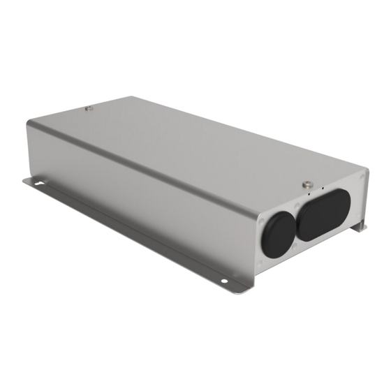
Installation Instructions
Interface Adaptor
CZ-CAPC4
Model No.
S
a
e f
y t
p
e r
c
a
t u
o i
n
s
Please Read Before Starting
This adaptor must be installed by the sales dealer or installer.
These instructions are all you need for most installation sites
and maintenance conditions. If you require help for a special
problem, contact our sales/service outlet or your certifi ed dealer
for additional instructions.
This symbol refers to a hazard or unsafe
WARNING
practice which can result in severe personal
injury or death.
This symbol refers to a hazard or unsafe
CAUTION
practice which can result in personal injury or
product or property damage.
We assume no responsibility for accidents or damages resulting
from methods other than those described in the installation
instructions or methods without using specified parts.
Malfunctions that occurred due to the unauthorised installation
methods are not covered by the product warranty.
This adaptor shall be installed in accordance with National
Wiring Regulations.
After the installation is complete, perform test operation to
confirm that no abnormality is present.
Read the installation instructions of devices to be connected as well.
When relocating or repairing this adaptor, provide the Installation
Instructions to the servicing personnel.
This appliance can be used by children aged from 8 years and
above and persons with reduced physical, sensory or mental
capabilities or lack of experience and knowledge if they have
been given supervision or instruction concerning use of the
appliance in a safe way and understand the hazards involved.
Children shall not play with the appliance.
Cleaning and user maintenance shall not be made by children
without supervision. The appliances is intended for household.
WARNING
ELECTRICAL SHOCK CAN CAUSE SEVERE
PERSONAL INJURY OR DEATH. ONLY A
QUALIFIED, EXPERIENCED ELECTRICIAN
SHOULD ATTEMPT TO WIRE THIS SYSTEM.
Highly dangerous electrical voltages are used in this
system. Carefully refer to the wiring diagram and
these instructions when wiring.
Improper connections and inadequate grounding can
cause accidental injury or death.
This adaptor is strongly recommended to be installed
with Earth Leakage Circuit Breaker (ELCB) or
Residual Current Device (RCD).
Otherwise, it may cause electrical shock and fire in
case of equipment breakdown or insulation
breakdown.
Earth Leakage Circuit Breaker (ELCB) must be
Printed in Singapore
incorporated in the fixed wiring in accordance with
the wiring regulations. The Earth Leakage Circuit
Breaker (ELCB) must be an approved 10 A, having a
contact separation by 3 mm in all poles.
Provide a power outlet to be used exclusively for this
adaptor.
Turn o the circuit breaker of the adaptors before
installation.
Do not supply power to the adaptor until all wiring is
completed or reconnected and checked.
Fix the power supply wiring securely with the
clamper so that the power supply terminal board is
free of tension (external force) when pulled.
Loose connection of the terminal board may occur
fire.
To prevent possible hazards from insulation
failure, the adaptor must be grounded.
Select an installation location which is rigid and
strong enough to support or hold the adaptor, and
select a location for easy maintenance.
This product must not be modified or disassembled
under any circumstances.
Modified or disassembled adaptor may cause fire,
electric shock or injury.
Do not clean inside the adaptor by users.
Engage authorized dealer or specialist for cleaning.
Do not operate with wet hands.
Ensure the electricity is off when connecting or
performing maintenance on lighting or electrical
devices and make sure there are no other people
around.
Take precautions when switching on the electricity
again when automatic restoration features are being
used.
CAUTION
Ground yourself to discharge static electricity before
performing any wiring.
Do not use the adaptor at the following locations.
Areas where leakage of flammable gas may be
expected
Places where large amounts of oil mist exist
Locations where external air may enter the room
directly (This may cause "condensation".)
Locations where high-frequency emissions are
generated
Location where voltage fluctuation frequently
occurs
Do not wash with water.
Panasonic Corporation
http://www.panasonic.com
1
NOTICE
The English text is the original instructions. Other languages are translation of the original instructions.
Refer to the PDF data for the Installation Instructions in other languages. Please contact to your local dealer to find PDF file for other
languages. (French, Spanish, German, Italian, Dutch, Portuguese, Russian, Ukrainian, Kazakh, Polish, Turkish)
Installation precautions
Avoid the following locations for installation.
Near a window where the unit is exposed to direct sunlight or
the open air
In unstable locations or locations where the unit is exposed to
shocks or vibrations (may cause the unit to fall)
Near heat sources
Control box
Where condensation forms
Install the unit vertically to the floor.
Install so that there is at least 50 mm gap
from the side where the wirings exit and at
10 mm
least 10 mm in each other direction. (Refer
to the diagram at right)
Install at least 1 m away from TV, radio,
PC, etc. (The unit may cause picture
distortion or noise)
Do not modify the unit such as by trying to
Wiring exit
install the circuit board into another device.
Use wiring with at least 1 mm in thickness
of insulation including the sheath.
Specifi cations
Model No.
CZ-CAPC4
Dimensions
(H) 165mm × (W) 302 mm × (D) 60 mm
Weight
1250 g
Temperature/
0 °C to 50 °C / 10% to 90%
Humidity range
(Indoor use only)
Rated voltage/
Single phase 100 – 240 V ~ 50 – 60 Hz
Rated frequency
Power consumption
Max. 4.0 W
Supplied accessories
< >: Number of pieces
Screws
Cable Tie
Tapping screws M4 × 20
<3>
<4>
Installation Instructions <1>
Wiring are not included ( field supplied item).
1. Mounting
Install near the target device or in a control box.
When connecting to a relay control device, connect to the device with wiring for input and output of 3 m or less.
(Connection wiring should be 0.5 mm
2
or more, and select connection wiring for the output wiring with suffi cient capacity to suit the
capacity of the device.)
Apart from the vertical mounting style, you can also mount the unit horizontally so the wirings exit the left or right sides.
When mounting so the wirings exit
from the bottom
Fix with 4 screws (supplied)
Dimensions
10 mm
10 mm
50 mm
Feature for automatically
restoring after a power outage
This unit is equipped with functionality to automatically restore itself
after a power outage.
(Refer to "4. The setting switches" for information on how to set)
After the power is restored, this feature automatically restores the
unit to the operational state it was in before an unexpected short-
term power outage occurred.
When using the feature for automatically restoring power after
an outage, if the power switch is switched off on purpose during
operation in order to perform maintenance on the device, for
example, then after the power switch is switched back on, the unit
will start working automatically.
Before performing maintenance on the unit, switch this breaker
off for safety purposes.
Before handing over this unit, make sure you explain to the person
in charge of safety and the client that a feature for automatically
restoring after a power outage is used in this unit.
When mounting so the wirings exit
from the top
(Allowed only when installing inside a
control box)
Fix with 4 screws (supplied)
2
(mm)
CAPC40012-2_1/3
Advertisement

Related Manuals for Panasonic CZ-CAPC4


Summary of Contents for Panasonic CZ-CAPC4
- Page 1 Installation Instructions languages. (French, Spanish, German, Italian, Dutch, Portuguese, Russian, Ukrainian, Kazakh, Polish, Turkish) Interface Adaptor Installation precautions Dimensions CZ-CAPC4 Model No. Avoid the following locations for installation. (mm) Near a window where the unit is exposed to direct sunlight or ...
- Page 2 These are the specific cations for the output terminal boards and input terminal boards. Case screw Remove the upper case. The output terminal boards (Case screws: 2) Upper case Using the setting switches (SW02), select the output signal that suits the controlled device and whether to have an operation answer back. Connect the power supply wiring.
- Page 3 (continued) Examples of connection circuit. [SW02-2] Operation answer back [SW02-5] Feature for automatically restoring after a Operation answer back input is not used. power outage Pulse contact output(Non-voltage contact “a” ) (SET output + RESET output) Special notes OFF: Operation answer back input is used. ON: Use the feature for automatically restoring after a power outage.
Need help?
Do you have a question about the CZ-CAPC4 and is the answer not in the manual?
Questions and answers