HP 8000f - Elite Ultra-slim Desktop PC Maintenance And Service Manual
Maintenance and service guide: hp compaq 8000f elite business pc ultra-slim desktop
Hide thumbs
Also See for 8000f - Elite Ultra-slim Desktop PC:
- Technical reference manual (114 pages) ,
- Hardware reference manual (48 pages) ,
- Quickspecs (26 pages)

Related Manuals for HP 8000f - Elite Ultra-slim Desktop PC


Summary of Contents for HP 8000f - Elite Ultra-slim Desktop PC
- Page 1 Maintenance and Service Guide HP Compaq 8000f Elite Business PC Ultra-slim Desktop...
- Page 2 No part of this document may be photocopied, reproduced, or translated to another language without the prior written consent of Hewlett-Packard Company. HP Compaq 8000f Elite Business PC Ultra-slim Desktop First Edition (February 2010) Document Part Number: 605648-001...
-
Page 3: About This Book
About This Book WARNING! Text set off in this manner indicates that failure to follow directions could result in bodily harm or loss of life. CAUTION: Text set off in this manner indicates that failure to follow directions could result in damage to equipment or loss of information. - Page 4 About This Book...
-
Page 5: Table Of Contents
Table of contents 1 Product Features ............................1 Front Panel Components ........................1 Rear Panel Components ........................2 2 Installing and Customizing the Software ...................... 3 Installing the Windows Operating System .................... 3 Downloading Microsoft Windows Updates ................... 3 Installing or Upgrading Device Drivers (Windows systems) ..............4 Customizing the Monitor Display (Windows systems) ................ - Page 6 Generating Static ....................... 23 Preventing Electrostatic Damage to Equipment ..............23 Personal Grounding Methods and Equipment ..............24 Grounding the Work Area ....................24 Recommended Materials and Equipment ................24 Operating Guidelines .......................... 25 Routine Care ............................26 General Cleaning Safety Precautions ................26 Cleaning the Computer Case ....................
- Page 7 Hard Drive Cage ..........................53 Port Cover ............................54 Front Fan ............................55 Card Reader ............................56 Speaker .............................. 57 Heat sink ............................58 Processor ............................59 System Board ............................. 61 Rear Fan ............................62 Battery ..............................63 Changing from Desktop to Tower Configuration ................65 Power Supply, External ........................
- Page 8 Using a Windows 7 operating system DVD (purchased separately) ....79 Windows Vista – Backup and Recovery ..................... 80 Backing up your information ....................80 Performing a recovery ....................... 81 Using the Windows recovery tools ..............81 Using F11 ......................82 Using a Windows Vista operating system DVD (purchased separately) ...
- Page 9 Contacting Customer Support ......................134 Appendix F POST Error Messages ....................... 135 POST Numeric Codes and Text Messages ..................136 Interpreting POST Diagnostic Front Panel LEDs and Audible Codes ..........143 Appendix G Password Security and Resetting CMOS ................146 Resetting the Password Jumper ......................
-
Page 11: Product Features
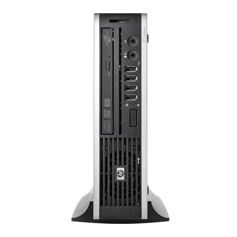
Product Features Front Panel Components Drive configuration may vary by model. Figure 1-1 Front Panel Components Table 1-1 Front Panel Components Optical Drive Microphone/Headphone Connector System Power LED USB (Universal Serial Bus) Ports SD Media Card Reader (optional) Hard Drive Activity Light Headphone Connector Dual-State Power Button NOTE:... -
Page 12: Rear Panel Components
Rear Panel Components Figure 1-2 Rear Panel Components Table 1-2 Rear Panel Components Line-Out Connector for powered audio Power Cord Connector devices (green) PS/2 Keyboard Connector (purple) Line-In Audio Connector (blue) Universal Serial Bus (USB) (6) PS/2 Mouse Connector (green) DisplayPort Monitor Connector RJ-45 Network Connector VGA Monitor Connector (blue) -
Page 13: Installing And Customizing The Software
Installing and Customizing the Software If your computer was not shipped with a Microsoft operating system, some portions of this documentation do not apply. Additional information is available in online help after you install the operating system. NOTE: If the computer was shipped with Windows Vista or Windows 7 loaded, you will be prompted to register the computer with HP Total Care before installing the operating system. -
Page 14: Installing Or Upgrading Device Drivers (Windows Systems)
Click on the Windows Update link. In Windows Vista and Windows 7, the Windows Update screen appears. Click view available updates and make sure all critical updates are selected. Click the Install button and follow the instructions on the screen. In Windows XP, you will be directed to the Microsoft Windows Update Web site. - Page 15 created and the software installed in order to get the most from your PC. The software and image file names are: ● Corel WinDVD SD and BD – installation software for WinDVD – used to play DVD movies ● HP Insight Diagnostics OR Vision Diagnostics – software to perform diagnostic activities on your Accessing Disk Image (ISO) Files...
-
Page 16: Computer Setup (F10) Utility
Computer Setup (F10) Utility Computer Setup (F10) Utilities Use Computer Setup (F10) Utility to do the following: ● Change factory default settings. ● Set the system date and time. ● Set, view, change, or verify the system configuration, including settings for processor, graphics, memory, audio, storage, communications, and input devices. -
Page 17: Using Computer Setup (F10) Utilities
● Solve system configuration errors detected but not automatically fixed during the Power-On Self- Test (POST). ● Replicate the system setup by saving system configuration information on diskette and restoring it on one or more computers. ● Execute self-tests on a specified ATA hard drive (when supported by drive). ●... -
Page 18: Computer Setup-File
Computer Setup—File NOTE: Support for specific Computer Setup options may vary depending on the hardware configuration. Table 3-2 Computer Setup—File Option Description System Information Lists: ● Product name ● SKU number (some models) ● Processor type/speed/stepping ● Cache size (L1/L2) (dual core processors have this listed twice) ●... -
Page 19: Computer Setup-Storage
Computer Setup—Storage NOTE: Support for specific Computer Setup options may vary depending on the hardware configuration. Table 3-3 Computer Setup—Storage Option Description Device Configuration Lists all installed BIOS-controlled storage devices. When a device is selected, detailed information and options are displayed. The following options may be presented: CD-ROM: No emulation options available. -
Page 20: Computer Setup-Security
Table 3-3 Computer Setup—Storage (continued) Storage Options Removable Media Boot Enables/disables ability to boot the system from removable media. SATA Emulation Allows you to choose how the SATA controller and devices are accessed by the operating system. There are three supported options: IDE, RAID, and AHCI. IDE - This is the most backwards-compatible setting of the three options. - Page 21 Table 3-4 Computer Setup—Security (continued) Power-On Password Allows you to set and enable a power-on password. The power-on password prompt appears after a power cycle. If the user does not enter the correct power-on password, the unit will not boot. NOTE: This password does not appear on warm boots , such as Ctrl+Alt+Delete...
- Page 22 Table 3-4 Computer Setup—Security (continued) USB Security Allows you to set Device Available/Device Hidden for: ● Front USB Ports ◦ USB Port 3 ◦ USB Port 4 ◦ USB Port 5 ◦ USB Port 6 ● Rear USB Ports ◦ USB Port 7 ◦...
- Page 23 Table 3-4 Computer Setup—Security (continued) System Security Data Execution Prevention (some models) (enable/disable) - Helps prevent operating system (some models: these security breaches. options are hardware PAVP (Models with Blu-ray drives) (disabled/min/max) - PAVP enables the Protected Audio Video dependent) Path in the Chipset.
- Page 24 Table 3-4 Computer Setup—Security (continued) Master Boot Record Protects the master boot record from viruses or other corruption. Saves of copy of the current Security master boot record. Setup Security Level Provides a method to allow end-users limited access to change specified setup options, without having to know the Setup Password.
-
Page 25: Computer Setup-Power
Computer Setup—Power NOTE: Support for specific Computer Setup options may vary depending on the hardware configuration. Table 3-5 Computer Setup—Power Option Description ● OS Power Runtime Power Management— Enable/Disable. Allows certain operating systems to reduce Management processor voltage and frequency when the current software load does not require the full capabilities of the processor. -
Page 26: Computer Setup-Advanced
Computer Setup—Advanced NOTE: Support for specific Computer Setup options may vary depending on the hardware configuration. Table 3-6 Computer Setup—Advanced (for advanced users) Option Heading Power-On Options Allows you to set: ● POST mode (QuickBoot, Clear Memory, FullBoot, or FullBoot Every x Days). ◦... - Page 27 Table 3-6 Computer Setup—Advanced (for advanced users) (continued) ◦ Clear Memory = No memory count on cold boot. Clears memory on all boots. ◦ FullBoot Every x Days = Memory count on 1st cold boot on or after the xth day. No more memory counts until 1st cold boot on or after x days.
- Page 28 Table 3-6 Computer Setup—Advanced (for advanced users) (continued) ● PCI Devices Lists currently installed PCI devices and their IRQ settings. ● Allows you to reconfigure IRQ settings for these devices or to disable them entirely. These settings have no effect under an ACPI-based operating system. PCI VGA Displayed only if there are multiple PCI video adapters in the system.
-
Page 29: Recovering The Configuration Settings
Table 3-6 Computer Setup—Advanced (for advanced users) (continued) Management Devices The Management Devices menu will only be displayed in the Advanced menu when the BIOS detects multiple management options. This option is for installed NIC cards that support ASF or DASH. Use the Management Devices menu to select if the BIOS management operations will be through the embedded solution or one of the installed NIC cards. -
Page 30: Serial Ata (Sata) Drive Guidelines And Features
Serial ATA (SATA) Drive Guidelines and Features NOTE: HP only supports the use of SATA hard drives on these models of computer. No Parallel ATA (PATA) drives are supported. SATA Hard Drives Serial ATA Hard Drive Characteristics Number of pins/conductors in data cable Number of pins in power cable Maximum data cable length 39.37 in (100 cm) -
Page 31: Smart Ata Drives
SMART ATA Drives The Self Monitoring Analysis and Recording Technology (SMART) ATA drives for the HP Personal Computers have built-in drive failure prediction that warns the user or network administrator of an impending failure or crash of the hard drive. The SMART drive tracks fault prediction and failure indication parameters such as reallocated sector count, spin retry count, and calibration retry count. -
Page 32: Identifying The Chassis, Routine Care, And Disassembly Preparation
Identifying the Chassis, Routine Care, and Disassembly Preparation This chapter provides general service information for the computer. Adherence to the procedures and precautions described in this chapter is essential for proper service. CAUTION: When the computer is plugged into an AC power source, voltage is always applied to the system board. -
Page 33: Electrostatic Discharge Information
Electrostatic Discharge Information A sudden discharge of static electricity from your finger or other conductor can destroy static-sensitive devices or microcircuitry. Often the spark is neither felt nor heard, but damage occurs. An electronic device exposed to electrostatic discharge (ESD) may not appear to be affected at all and can work perfectly throughout a normal cycle. -
Page 34: Personal Grounding Methods And Equipment
● Always be properly grounded when touching a sensitive component or assembly. ● Avoid contact with pins, leads, or circuitry. ● Place reusable electrostatic-sensitive parts from assemblies in protective packaging or conductive foam. Personal Grounding Methods and Equipment Use the following equipment to prevent static electricity damage to equipment: ●... -
Page 35: Operating Guidelines
● Conductive bins and other assembly or soldering aids ● Conductive foam ● Conductive tabletop workstations with ground cord of one-megohm +/- 10% resistance ● Static-dissipative table or floor mats with hard tie to ground ● Field service kits ● Static awareness labels ●... -
Page 36: Routine Care
● Never cover the ventilation slots on the monitor with any type of material. ● Install or enable power management functions of the operating system or other software, including sleep states. Routine Care General Cleaning Safety Precautions Never use solvents or flammable solutions to clean the computer. Never immerse any parts in water or cleaning solutions;... -
Page 37: Cleaning The Monitor
CAUTION: Use safety glasses equipped with side shields before attempting to clean debris from under the keys. ● Visible debris underneath or between the keys may be removed by vacuuming or shaking. ● Canned, pressurized air may be used to clean debris from under the keys. Caution should be used as too much air pressure can dislodge lubricants applied under the wide keys. -
Page 38: Tools And Software Requirements
Tools and Software Requirements To service the computer, you need the following: ● Torx T-15 screwdriver (HP screwdriver with bits, PN 161946-001) ● Torx T-15 screwdriver with small diameter shank (for certain front bezel removal) ● Flat-bladed screwdriver (may sometimes be used in place of the Torx screwdriver) ●... -
Page 39: Lithium Coin Cell Battery
● Before handling a drive, ensure that you are discharged of static electricity. While handling a drive, avoid touching the connector. For more information about preventing electrostatic damage, refer to Electrostatic Discharge Information on page 23 ● Do not use excessive force when inserting a drive. ●... -
Page 40: Removal And Replacement Procedures
Removal and Replacement Procedures Adherence to the procedures and precautions described in this chapter is essential for proper service. After completing all necessary removal and replacement procedures, run the Diagnostics utility to verify that all components operate properly. NOTE: Not all features listed in this guide are available on all computers. Preparation for Disassembly Identifying the Chassis, Routine Care, and Disassembly Preparation on page 22 for initial safety... -
Page 41: Serial Number Location
Serial Number Location Each computer has a unique serial number and a product ID that are located on the top of the computer when it is in the tower configuration. Keep these numbers available for use when contacting customer service for assistance. Figure 6-1 Serial Number and Product ID Location Serial Number Location... -
Page 42: Security Lock Provisions
Security Lock Provisions NOTE: For information on data security features, refer to the Desktop Management Guide and the HP ProtectTools Security Manager Guide (some models) at http://www.hp.com. The security locks displayed below and on the following pages can be used to secure the computer. Installing a Security Lock HP/Kensington MicroSaver Security Cable Lock There are two cable lock slots on the rear of the computer. -
Page 43: Padlock
Padlock Figure 6-4 Installing a Padlock HP Business PC Security Lock Fasten the security cable by looping it around a stationary object. Figure 6-5 Securing the Cable to a Fixed Object Security Lock Provisions... - Page 44 Thread the keyboard and mouse cables through the lock. Figure 6-6 Threading the Keyboard and Mouse Cables Screw the lock to the chassis using the screw provided. Figure 6-7 Attaching the Lock to the Chassis Chapter 6 Removal and Replacement Procedures...
- Page 45 Insert the plug end of the security cable into the lock (1) and push the button in (2) to engage the lock. Use the key provided to disengage the lock. Figure 6-8 Engaging the Lock Security Lock Provisions...
-
Page 46: Front Bezel Security
Front Bezel Security The front bezel can be locked in place by installing a security screw provided by HP. To install the security screw: Remove/disengage any security devices that prohibit opening the computer. Remove all removable media, such as compact discs or USB flash drives, from the computer. Turn off the computer properly through the operating system, then turn off any external devices. - Page 47 Install the security screw through the middle front bezel release tab and into the chassis to secure the front bezel in place. Figure 6-10 Installing the Front Bezel Security Screw Replace the access panel. If the computer was on a stand, replace the stand. Reconnect the power cord and turn on the computer.
-
Page 48: Computer Access Panel
Computer Access Panel To access internal components, you must remove the access panel: Prepare the computer for disassembly (Preparation for Disassembly on page 30). Loosen the thumbscrew on the rear of the computer (1), slide the access panel toward the front of the computer, and then lift it off (2). -
Page 49: Front Bezel
Front Bezel Prepare the computer for disassembly (Preparation for Disassembly on page 30). Remove the computer access panel (Computer Access Panel on page 38). Lift up the three tabs on the side of the bezel (1), then rotate the bezel off the chassis (2). Figure 6-12 Removing the Front Bezel To install the front bezel, reverse the removal procedure. -
Page 50: Bezel Blank
Bezel Blank On some models, there is a bezel blank covering the external drive bay that needs to be removed before installing a drive. To remove a bezel blank: Remove the computer access panel (Computer Access Panel on page 38). Remove the front bezel (Front Bezel on page 39). -
Page 51: Installing Additional Memory
Installing Additional Memory The computer comes with double data rate 3 synchronous dynamic random access memory (DDR3- SDRAM) small outline dual inline memory modules (SODIMMs). SODIMMs The memory sockets on the system board can be populated with up to two industry-standard SODIMMs. -
Page 52: Populating Sodimm Sockets
Populating SODIMM Sockets There are two SODIMM sockets on the system board, with one socket per channel. The sockets are labeled XMM1 and XMM3. The XMM1 socket operates in memory channel A. The XMM3 socket operates in memory channel B. Figure 6-14 SODIMM Socket Locations Table 6-1... -
Page 53: Installing Sodimms
Installing SODIMMs CAUTION: You must disconnect the power cord before adding or removing memory modules. Regardless of the power-on state, voltage is always supplied to the memory modules as long as the computer is plugged into an active AC outlet. Adding or removing memory modules while voltage is present may cause irreparable damage to the memory modules or system board. - Page 54 Slide the new SODIMM into the socket at approximately a 30° angle (1) then press the SODIMM down (2) so that the latches lock it in place. Figure 6-16 Installing a SODIMM NOTE: A memory module can be installed in only one way. Match the notch on the module with the tab on the memory socket.
-
Page 55: Cable Management
Cable Management Always follow good cable management practices when working inside the computer. ● Keep cables away from major heat sources like the heat sink. ● Do not jam cables on top of expansion cards or memory modules. Printed circuit cards like these are not designed to take excessive pressure on them. -
Page 56: Replacing The Optical Drive
Replacing the Optical Drive The Ultra-Slim Desktop uses a slimline Serial ATA (SATA) optical drive. Removing the Existing Optical Drive Prepare the computer for disassembly (Preparation for Disassembly on page 30). If the computer is on a stand, remove the computer from the stand and lay the computer down. Remove the computer access panel (Computer Access Panel on page 38). -
Page 57: Preparing The New Optical Drive
Preparing the New Optical Drive Before the new optical drive can be used, the release latch must be attached. Peel the backing off the adhesive on the release latch. Without allowing the release latch to touch the optical drive, carefully align the holes on the release latch with the pins on the side of the optical drive. -
Page 58: Installing The New Optical Drive
Installing the New Optical Drive NOTE: If you are installing an optical drive in a bay that did not previously have a drive in it, you must remove the access panel and the bezel blank covering the opening of the bay before proceeding. -
Page 59: Hard Drive
Hard Drive NOTE: The Ultra-Slim Desktop supports only 2.5-inch Serial ATA (SATA) internal hard drives; parallel ATA (PATA) internal hard drives are not supported. Before you remove the old hard drive, be sure to back up the data from the old hard drive so that you can transfer the data to the new hard drive. - Page 60 Lift the hard drive carrier straight up and out of the chassis. Figure 6-21 Removing the Hard Drive Carrier Remove the four guide screws from the sides of the hard drive carrier. Figure 6-22 Removing the Guide Screws Lift the hard drive up to the top of the carrier (1) and slide the drive out of the carrier (2). Figure 6-23 Removing the Hard Drive from the Carrier Chapter 6 Removal and Replacement Procedures...
- Page 61 Position the hard drive so that the top of the hard drive is up against the top of the carrier (1) so that the circuit board on the bottom of the hard drive does not come in contact wit the tabs on the bottom of the carrier, then slide the new hard drive into the carrier (2).
- Page 62 To place the hard drive carrier back in the chassis, align the guide screws with the slots on the drive bay, drop the carrier straight down into the drive bay (1), and press the handle on the carrier all the way down (2) so that the drive is properly seated and locked in place. Figure 6-26 Installing the Hard Drive Carrier Replace the optical drive and reconnect the cable on the back of the optical drive.
-
Page 63: Hard Drive Cage
Hard Drive Cage The drive cage sits behind the USB ports on the front of the chassis. Prepare the computer for disassembly (Preparation for Disassembly on page 30). Remove the computer access panel (Computer Access Panel on page 38). Remove the optical drive and connector (Removing the Existing Optical Drive on page 46). -
Page 64: Port Cover
Port Cover An optional rear port cover is available for the computer. To install the port cover: Thread the cables through the bottom hole on the port cover (1) and connect the cables to the rear ports on the computer. Insert the hooks on the port cover into the slots on the rear of the chassis, then slide the cover to the right to secure it in place (2). -
Page 65: Front Fan
Front Fan The front fan sits against the front on the left side of the chassis. Prepare the computer for disassembly (Preparation for Disassembly on page 30). Remove the computer access panel (Computer Access Panel on page 38). Disconnect the fan control cable from the red system board connector labeled CHFAN. Tilt the fan slightly toward the rear of the computer, and then lift the fan straight up and out of the chassis. -
Page 66: Card Reader
Card Reader The card reader is secured to the front right corner of the chassis. Prepare the computer for disassembly (Preparation for Disassembly on page 30). Remove the computer access panel (Computer Access Panel on page 38). Remove the front bezel (Front Bezel on page 39). -
Page 67: Speaker
Speaker The speaker is secured to the front of the chassis between the fan and the I/O ports. Prepare the computer for disassembly (Preparation for Disassembly on page 30). Remove the computer access panel (Computer Access Panel on page 38). Remove the front bezel (Front Bezel on page 39). -
Page 68: Heat Sink
Heat sink The heat sink is secured by four Torx T15 screws. It does not have an attached fan. Prepare the computer for disassembly (Preparation for Disassembly on page 30). Remove the computer access panel (Computer Access Panel on page 38). -
Page 69: Processor
CAUTION: Heat sink retaining screws should be tightened in diagonally opposite pairs (as in an X) to evenly seat the heat sink on the processor. This is especially important as the pins on the socket are very fragile and any damage to them may require replacing the system board. Processor Prepare the computer for disassembly (Preparation for Disassembly on page... - Page 70 Position the heat sink atop the processor. If using a new heat sink, remove the protective covering from the bottom of the heat sink and place it in position atop the processor. Secure the heat sink to the system board and system board tray with the 4 captive screws and attach the heat sink control cable to the system board.
-
Page 71: System Board
System Board CAUTION: Be very careful when removing or replacing the system board to prevent damaging it. Prepare the computer for disassembly (Preparation for Disassembly on page 30). Remove the computer access panel (Computer Access Panel on page 38). Remove the front bezel (Front Bezel on page 39). -
Page 72: Rear Fan
Remove the three remaining screws that secure the system board to the chassis. Figure 6-36 Removing the system board Slide system board toward the front of the unit until the rear connectors are clear of their slots in the chassis. Lift the rear of the system board until it clears the chassis, and then remove the system board from the chassis. -
Page 73: Battery
Remove the hard drive cage (Hard Drive Cage on page 53). Remove the system board (System Board on page 61). Disconnect the fan control cable from the red/brown system board connector labeled CHFAN2. From the outside of the chassis, remove the four Phillips screws that secure the fan to the chassis, then from the inside of the chassis, slide the fan forward and lift it up and out of the chassis. - Page 74 CAUTION: Static electricity can damage the electronic components of the computer or optional equipment. Before beginning these procedures, ensure that you are discharged of static electricity by briefly touching a grounded metal object. Prepare the computer for disassembly (Preparation for Disassembly on page 30).
-
Page 75: Changing From Desktop To Tower Configuration
Changing from Desktop to Tower Configuration Prepare the computer for disassembly (Preparation for Disassembly on page 30). Place the computer firmly down into the stand. Figure 6-39 Placing the Computer on the Stand Reconnect the external equipment, plug the power cord into a power outlet, and turn the computer on. -
Page 76: Power Supply, External
Power Supply, External The USDT chassis uses an external power supply. WARNING! To reduce potential safety issues, only the power supply provided with the computer, a replacement power supply provided by HP, or a power supply purchased as an accessory from HP should be used with the computer. -
Page 77: Appendix A Connector Pin Assignments
Connector Pin Assignments This appendix contains the pin assignments for many computer and workstation connectors. Some of these connectors may not be used on the product being serviced. Keyboard Connector and Icon Signal Data Unused Ground +5 VDC Clock Unused Mouse Connector and Icon Signal... -
Page 78: Ethernet Rj-45
Ethernet RJ-45 Connector and Icon Signal (+) Transmit Data (-) Transmit Data (+) Receive Data Unused Unused (-) Receive Data Unused Unused Serial Interface, Powered and Non-Powered Connector and Icon Signal Carrier Detect (12V if powered) Receive Data Transmit Data Data Terminal Ready Signal Ground Data Set Ready... -
Page 79: Microphone
Microphone Connector and Icon (1/8” miniphone) Signal 1 (Tip) Audio_left 1 2 3 2 (Ring) Power_Right 3 (Shield) Audio_right Headphone Connector and Icon (1/8” miniphone) Signal 1 (Tip) Audio_left 1 2 3 2 (Ring) Power_Right 3 (Shield) Ground Line-in Audio Connector and Icon (1/8”... -
Page 80: Monitor
Monitor Connector and Icon Signal Signal Red Analog +5V (fused) Green Analog Ground Blue Analog Not used Not used DDC Serial Data Ground Horizontal Sync Ground Vertical Sync Ground DDC Serial Clock Ground DisplayPort Connector and Icon TOP ROW BOTTOM ROW Signal Type Pin Name Signal Type... -
Page 81: 4-Pin Power (For Cpu)
4-Pin Power (for CPU) Connector and Icon Signal +12V CPU -12V CPU 6-Pin Power (for CPU) (CMT, SFF) Connector and Icon Signal 12V CPU 12V CPU +12V SATA Data and Power Drive Connector Signal Signal Signal Signal Ground Ground Ground Ground V 3.3 V 3.3... -
Page 82: Pci Express
PCI Express x1, x4, x8, and x16 PCI Express Connector Pin A Signal Signal Signal Signal Signal PRSNT1 JTAG3 PERST# PERp0 PERp1 +12V JTAG4 PERn0 PERn1 +12V JTAG5 REFCLK+ +3.3V REFCLK- RSVD JTAG2 +3.3V PERp2 PERn(2) PERn4 RSVD PERp7 RSVD PERp6 PERn7 PERp3... -
Page 83: Pci Express
PCI Express x1, x4, x8, and x16 PCI Express Connector Pin B Signal Signal Signal Signal Signal +12V SMDAT WAKE# +12V RSVD RSVD +3.3 V PETp2 JTAG1 PETp0 PETp1 PETn2 SMCLK 3.3vAux PETn0 PETn1 PRSNT2# PETp6 PETn7 PETp3 PETp5 PRTn6 PETn3 PETp4 PETn5... -
Page 84: Appendix B Power Cord Set Requirements
Power Cord Set Requirements The power supplies on some computers have external power switches. The voltage select switch feature on the computer permits it to operate from any line voltage between 100-120 or 220-240 volts AC. Power supplies on those computers that do not have external power switches are equipped with internal switches that sense the incoming voltage and automatically switch to the proper voltage. -
Page 85: Country-Specific Requirements
Country-Specific Requirements Additional requirements specific to a country are shown in parentheses and explained below. Country Accrediting Agency Country Accrediting Agency Australia (1) EANSW Italy (1) Austria (1) Japan (3) METI Belgium (1) CEBC Norway (1) NEMKO Canada (2) Sweden (1) SEMKO Denmark (1) DEMKO... -
Page 86: Appendix C Backup And Recovery
Backup and Recovery Windows 7 – Backup and Recovery To protect your information, use Windows Backup and Restore to back up individual files and folders, back up your entire hard drive (select models only), create system repair discs (select models only), or create system restore points. -
Page 87: Performing A Recovery
● Save customized settings that appear in a window, toolbar, or menu bar by taking a screen shot of your settings. The screen shot can be a time-saver if you have to reset your preferences. To create a screen shot: Display the screen you want to save. -
Page 88: Using The Windows Recovery Tools
NOTE: If you are unable to boot (start up) your computer and you cannot use the system repair discs you previously created (select models only), you must purchase a Windows 7 operating system DVD to reboot the computer and repair the operating system. For additional information, refer to the “Using a Windows 7 operating system DVD (purchased separately)”... -
Page 89: Using A Windows 7 Operating System Dvd (Purchased Separately)
To recover the original hard drive image using F11, follow these steps: If possible, back up all personal files. If possible, check for the presence of the HP Recovery partition: select Start, right-click Computer, click Manage, and then click Disk Management. NOTE: If the HP Recovery partition is not listed, you must recover your operating system and programs using the Windows 7 operating system DVD and the Driver Recovery disc (both... -
Page 90: Windows Vista - Backup And Recovery
Windows Vista – Backup and Recovery To protect your information, use the Backup and Restore Center to back up individual files and folders, back up your entire hard drive (select models only), or create system restore points. In case of system failure, you can use the backup files to restore the contents of your computer. The Backup and Restore Center provides the following options: ●... -
Page 91: Performing A Recovery
● When backing up to discs, use any of the following types of discs (purchased separately): CD-R, CD-RW, DVD+R, DVD+R DL, DVD-R, DVD-R DL, or DVD±RW. The discs you use will depend on the type of optical drive installed in your computer. NOTE: DVDs and DVDs with double-layer (DL) support store more information than CDs, so using them for backup reduces the number of recovery discs required. -
Page 92: Using F11
CAUTION: Using Startup Repair completely erases hard drive contents and reformats the hard drive. All files you have created and any software installed on the computer are permanently removed. When reformatting is complete, the recovery process restores the operating system, as well as the drivers, software, and utilities from the backup used for recovery. - Page 93 To initiate recovery using a Windows Vista operating system DVD, follow these steps: NOTE: This process takes several minutes. If possible, back up all personal files. Restart the computer, and then insert the Windows Vista operating system DVD into the optical drive before the Windows operating system loads.
-
Page 94: Appendix D Computer Diagnostic Features
Computer Diagnostic Features Hewlett-Packard Vision Diagnostics NOTE: HP Vision Diagnostics is included on CD with some computer models only. The Hewlett-Packard Vision Diagnostics utility allows you to view information about the hardware configuration of the computer and perform hardware diagnostic tests on the subsystems of the computer. -
Page 95: Survey Tab
Turn on the computer. The system will boot into HP Vision Diagnostics. NOTE: If the system does not boot to the CD in the optical drive or to the USB flash drive, you may need to change the boot order in the Computer Setup (F10) utility. At the boot menu, select either the HP Vision Diagnostics utility to test the various hardware components in the computer or the HP Memory Test utility to test memory only. -
Page 96: Status Tab
There are three types of tests to choose from: ● Quick Test—Provides a predetermined script where a sample of each hardware component is exercised. You may further modify which of the Quick tests are executed by selecting or deselecting individual tests in the hardware component check list. ●... -
Page 97: History Tab
● The test progress for each device being tested ● The elapsed test times for each device being tested History Tab The History tab contains information on past test executions. The History Log displays all tests that have been executed, the number of times of execution, the number of times failed, the date each test was executed, and the time it took to complete each test. -
Page 98: Saving And Printing Information In Hp Vision Diagnostics
The Test Components section provides a description of each test, as well as the parameters that may be adjusted when running in Custom test mode. The Defect codes section contains information on the numerical error code that may appear in the Errors tab. -
Page 99: Protecting The Software
Protecting the Software To protect software from loss or damage, you should keep a backup copy of all system software, applications, and related files stored on the hard drive. See the operating system or backup utility documentation for instructions on making backup copies of data files. Protecting the Software... -
Page 100: Appendix E Troubleshooting Without Diagnostics
Troubleshooting Without Diagnostics This chapter provides information on how to identify and correct minor problems, such as diskette drive, hard drive, optical drive, graphics, audio, memory, and software problems. If you encounter problems with the computer, refer to the tables in this chapter for probable causes and recommended solutions. -
Page 101: Helpful Hints
● Refer to the comprehensive online technical support at http://www.hp.com/support. ● Refer to Helpful Hints on page 91 in this guide. To assist you in resolving problems online, HP Instant Support Professional Edition provides you with self-solve diagnostics. If you need to contact HP support, use HP Instant Support Professional Edition's online chat feature. - Page 102 ● Wake the computer by pressing any key on the keyboard or pressing the power button. If the system remains in suspend mode, shut down the computer by pressing and holding the power button for at least four seconds then press the power button again to restart the computer. If the system will not shut down, unplug the power cord, wait a few seconds, then plug it in again.
-
Page 103: Solving General Problems
Solving General Problems You may be able to easily resolve the general problems described in this section. If a problem persists and you are unable to resolve it yourself or if you feel uncomfortable about performing the operation, contact an authorized dealer or reseller. WARNING! When the computer is plugged into an AC power source, voltage is always applied to the system board. - Page 104 Table E-1 Solving General Problems (continued) There is no sound or sound volume is too low. Cause Solution System volume may be set low or muted. Check the F10 BIOS settings to make sure the internal system speaker is not muted (this setting does not affect the external speakers).
- Page 105 Table E-1 Solving General Problems (continued) Poor performance is experienced. Cause Solution Too many applications running. Close unnecessary applications to free up memory. Add more memory. Some applications run in the background and can be closed by right-clicking on their corresponding icons in the task tray.
- Page 106 Table E-1 Solving General Problems (continued) System does not power on and the LEDs on the front of the computer are not flashing. Cause Solution System unable to power on. Press and hold the power button for less than 4 seconds. If the hard drive LED turns green, then: Check that the voltage selector, located on the rear of the power supply on some models, is set to the...
-
Page 107: Solving Power Problems
Solving Power Problems Common causes and solutions for power problems are listed in the following table. Table E-2 Solving Power Problems Power supply shuts down intermittently. Cause Solution Voltage selector switch on rear of computer chassis (some Select the proper AC voltage using the selector switch. models) not switched to correct line voltage (115V or 230V). -
Page 108: Solving Diskette Problems
Solving Diskette Problems Common causes and solutions for diskette problems are listed in the following table. NOTE: The computer does not support internal diskette drives. Only USB diskette drives are supported. NOTE: You may need to reconfigure the computer when you add or remove hardware, such as an additional diskette drive. - Page 109 Table E-3 Solving Diskette Problems (continued) Cannot format diskette. Cause Solution Invalid media reported. When formatting a disk in MS-DOS, you may need to specify diskette capacity. For example, to format a 1.44-MB diskette, type the following command at the MS-DOS prompt: FORMAT A: /F:1440 Disk may be write-protected.
- Page 110 Table E-3 Solving Diskette Problems (continued) Cannot Boot to Diskette. Cause Solution Diskette boot has been disabled in Computer Setup. Run Computer Setup and enable USB device in Storage > Boot Order. Run Computer Setup and enable diskette boot in Storage >...
-
Page 111: Solving Hard Drive Problems
Solving Hard Drive Problems Table E-4 Solving Hard Drive Problems Hard drive error occurs. Cause Solution Hard disk has bad sectors or has failed. In Microsoft Windows XP, right-click Start, click Explore, and select a drive. Select File > Properties > Tools. - Page 112 Table E-4 Solving Hard Drive Problems (continued) Nonsystem disk/NTLDR missing message. Cause Solution The system is trying to start from a diskette that is not Remove the diskette from the diskette drive. bootable. The system is trying to start from the hard drive but the hard Insert a bootable diskette into the diskette drive and drive may have been damaged.
- Page 113 Table E-4 Solving Hard Drive Problems (continued) Computer seems to be locked up. Cause Solution Program in use has stopped responding to commands. Attempt the normal Windows “Shut Down” procedure. If this fails, press the power button for four or more seconds to turn off the power.
-
Page 114: Solving Media Card Reader Problems
Solving Media Card Reader Problems Table E-5 Solving Media Card Reader Problems Media card will not work in a digital camera after formatting it in Microsoft Windows XP or Microsoft Windows Vista. Cause Solution By default, Windows XP and Windows Vista will format any Either format the media card in the digital camera or select media card with a capacity greater than 32MB with the FAT file system to format the media card in a computer with... - Page 115 Table E-5 Solving Media Card Reader Problems (continued) Do not know how to remove a media card correctly. Cause Solution The computer’s software is used to safely eject the card. Open My Computer (Windows XP) or Computer (Windows Vista and Windows 7), right-click on the corresponding drive icon, and select Eject.
-
Page 116: Solving Display Problems
Solving Display Problems If you encounter display problems, see the documentation that came with the monitor and to the common causes and solutions listed in the following table. Table E-6 Solving Display Problems Blank screen (no video). Cause Solution Monitor is not turned on and the monitor light is not on. Turn on the monitor and check that the monitor light is on. - Page 117 Table E-6 Solving Display Problems (continued) Blank screen and the power LED flashes Red five times, once every second, followed by a two second pause, and the computer beeps five times. (Beeps stop after fifth iteration but LEDs continue flashing.) Cause Solution Pre-video memory error.
- Page 118 Table E-6 Solving Display Problems (continued) Blurry video or requested resolution cannot be set. Cause Solution If the graphics controller was upgraded, the correct graphics Install the video drivers included in the upgrade kit. drivers may not be loaded. Monitor is not capable of displaying requested resolution. Change requested resolution.
- Page 119 Table E-6 Solving Display Problems (continued) Vibrating or rattling noise coming from inside a CRT monitor when powered on. Cause Solution Monitor degaussing coil has been activated. None. It is normal for the degaussing coil to be activated when the monitor is powered on. Clicking noise coming from inside a CRT monitor.
-
Page 120: Solving Audio Problems
Solving Audio Problems If the computer has audio features and you encounter audio problems, see the common causes and solutions listed in the following table. Table E-7 Solving Audio Problems Sound cuts in and out. Cause Solution Processor resources are being used by other open Shut down all open processor-intensive applications. - Page 121 Table E-7 Solving Audio Problems (continued) Sound does not come out of the speaker or headphones. Cause Solution Computer is in standby mode. Press the power button to resume from standby mode. CAUTION: When attempting to resume from standby mode, do not hold down the power button for more than four seconds.
- Page 122 Table E-7 Solving Audio Problems (continued) There is no sound or sound volume is too low. Cause Solution The application is set to use a different audio device than Some graphics cards support audio over the DisplayPort speakers. connection, so multiple audio devices may be listed in Device Manager.
-
Page 123: Solving Printer Problems
Solving Printer Problems If you encounter printer problems, see the documentation that came with the printer and to the common causes and solutions listed in the following table. Table E-8 Solving Printer Problems Printer will not print. Cause Solution Printer is not turned on and online. Turn the printer on and make sure it is online. -
Page 124: Solving Keyboard And Mouse Problems
Solving Keyboard and Mouse Problems If you encounter keyboard or mouse problems, see the documentation that came with the equipment and to the common causes and solutions listed in the following table. Table E-9 Solving Keyboard Problems Keyboard commands and typing are not recognized by the computer. Cause Solution Keyboard connector is not properly connected. - Page 125 Table E-10 Solving Mouse Problems (continued) Mouse does not respond to movement or is too slow. Cause Solution Mouse may need cleaning. Remove the roller ball cover on the mouse and clean the internal components. Mouse may need repair. See the Worldwide Limited Warranty for terms and conditions.
-
Page 126: Solving Hardware Installation Problems
Solving Hardware Installation Problems You may need to reconfigure the computer when you add or remove hardware, such as an additional drive or expansion card. If you install a plug and play device, Windows automatically recognizes the device and configures the computer. If you install a non–plug and play device, you must reconfigure the computer after completing installation of the new hardware. - Page 127 Table E-11 Solving Hardware Installation Problems (continued) Power LED flashes Red five times, once every second, followed by a two second pause, and the computer beeps five times. (Beeps stop after fifth iteration but LEDs continue flashing.) Cause Solution Memory is installed incorrectly or is bad. CAUTION: To avoid damage to the DIMMs or the system board, you must unplug the computer power cord before...
-
Page 128: Solving Network Problems
Solving Network Problems Some common causes and solutions for network problems are listed in the following table. These guidelines do not discuss the process of debugging the network cabling. Table E-12 Solving Network Problems Wake-on-LAN feature is not functioning. Cause Solution S5 Maximum Power Saving feature is enabled. - Page 129 Table E-12 Solving Network Problems (continued) Network driver does not detect network controller. Cause Solution Network controller is disabled. Run Computer Setup and enable network controller. Enable the network controller in the operating system via Device Manager. Incorrect network driver. Check the network controller documentation for the correct driver or obtain the latest driver from the manufacturer’s Web site.
- Page 130 Table E-12 Solving Network Problems (continued) Diagnostics passes, but the computer does not communicate with the network. Cause Solution Network drivers are not loaded, or driver parameters do not Make sure the network drivers are loaded and that the driver match current configuration.
- Page 131 Table E-12 Solving Network Problems (continued) System setup utility reports unprogrammed EEPROM. Cause Solution Unprogrammed EEPROM. Contact an authorized service provider. Solving Network Problems 121...
-
Page 132: Solving Memory Problems
Solving Memory Problems If you encounter memory problems, some common causes and solutions are listed in the following table. CAUTION: Power may still be supplied to the DIMMs when the computer is turned off (depending on the Management Engine (ME) settings). To avoid damage to the DIMMs or the system board, you must unplug the computer power cord before attempting to reseat, install, or remove a DIMM module. - Page 133 Table E-13 Solving Memory Problems (continued) Insufficient memory error during operation. Cause Solution Too many Terminate and Stay Resident programs (TSRs) Delete any TSRs that you do not need. are installed. You have run out of memory for the application. Check the memory requirements for the application or add more memory to the computer.
-
Page 134: Solving Processor Problems
Solving Processor Problems If you encounter processor problems, common causes and solutions are listed in the following table. Table E-14 Solving Processor Problems Poor performance is experienced. Cause Solution Processor is hot. Make sure the airflow to the computer is not blocked. Make sure the fans are connected and working properly (some fans only operate when needed). -
Page 135: Solving Cd-Rom And Dvd Problems
Solving CD-ROM and DVD Problems If you encounter CD-ROM or DVD problems, see the common causes and solutions listed in the following table or to the documentation that came with the optional device. Table E-15 Solving CD-ROM and DVD Problems System will not boot from CD-ROM or DVD drive. - Page 136 Table E-15 Solving CD-ROM and DVD Problems (continued) Movie will not play in the DVD drive. Cause Solution Movie may be regionalized for a different country. See the documentation that came with the DVD drive. Decoder software is not installed. Install decoder software.
- Page 137 USDT computer boots too slow after removing a CD-ROM or DVD drive. Cause Solution The system is searching for the drive during boot because Disconnect the drive cable from the system board. the drive cable is still attached to the system board. Solving CD-ROM and DVD Problems 127...
-
Page 138: Solving Usb Flash Drive Problems
Solving USB Flash Drive Problems If you encounter USB flash drive problems, common causes and solutions are listed in the following table. Table E-16 Solving USB Flash Drive Problems USB flash drive is not seen as a drive letter in Windows. Cause Solution The drive letter after the last physical drive is not available. -
Page 139: Solving Front Panel Component Problems
Solving Front Panel Component Problems If you encounter problems with devices connected to the front panel, refer to the common causes and solutions listed in the following table. Table E-17 Solving Front Panel Component Problems A USB device, headphone, or microphone is not recognized by the computer. Cause Solution Device is not properly connected. -
Page 140: Solving Internet Access Problems
Solving Internet Access Problems If you encounter Internet access problems, consult your Internet Service Provider (ISP) or refer to the common causes and solutions listed in the following table. Table E-18 Solving Internet Access Problems Unable to connect to the Internet. Cause Solution Internet Service Provider (ISP) account is not set up... - Page 141 Table E-18 Solving Internet Access Problems (continued) Unable to connect to the Internet. Cause Solution IP address is not configured properly. Contact your ISP for the correct IP address. Cookies are corrupted. (A “cookie” is a small piece of Windows XP information that a Web server can store temporarily with the Select Start >...
- Page 142 Table E-18 Solving Internet Access Problems (continued) Internet takes too long to download Web sites. Cause Solution Modem is not set up properly. Verify that the modem is connected and communicating properly. Windows XP Select Start > Control Panel. Double-click System. Click the Hardware tab.
-
Page 143: Solving Software Problems
Solving Software Problems Most software problems occur as a result of the following: ● The application was not installed or configured correctly. ● There is insufficient memory available to run the application. ● There is a conflict between applications. ● Be sure that all the needed device drivers have been installed. -
Page 144: Contacting Customer Support
Contacting Customer Support For help and service, contact an authorized reseller or dealer. To locate a reseller or dealer near you, visit http://www.hp.com. NOTE: If you take the computer to an authorized reseller, dealer, or service provider for service, remember to provide the setup and power-on passwords if they are set. Refer to the number listed in the warranty or in the Support Telephone Numbers guide for technical assistance. -
Page 145: Appendix F Post Error Messages
POST Error Messages This appendix lists the error codes, error messages, and the various indicator light and audible sequences that you may encounter during Power-On Self-Test (POST) or computer restart, the probable source of the problem, and steps you can take to resolve the error condition. POST Message Disabled suppresses most system messages during POST, such as memory count and non-error text messages. -
Page 146: Post Numeric Codes And Text Messages
POST Numeric Codes and Text Messages This section covers those POST errors that have numeric codes associated with them. The section also includes some text messages that may be encountered during POST. NOTE: The computer will beep once after a POST text message is displayed on the screen. Table F-1 Numeric Codes and Text Messages Control panel message... - Page 147 Table F-1 Numeric Codes and Text Messages (continued) Control panel message Description Recommended action 163-Time & Date Not Set Invalid time or date in configuration Reset the date and time under Control memory. Panel (Computer Setup can also be used). If the problem persists, replace the RTC RTC (real-time clock) battery may need to battery.
- Page 148 Table F-1 Numeric Codes and Text Messages (continued) Control panel message Description Recommended action 303-Keyboard Controller Error I/O board keyboard controller. Reconnect keyboard with computer turned off. Replace the system board. 304-Keyboard or System Unit Error Keyboard failure. Reconnect the keyboard with computer turned off.
- Page 149 Table F-1 Numeric Codes and Text Messages (continued) Control panel message Description Recommended action 605-Diskette Drive Type Error Mismatch in drive type. Disconnect any other diskette controller devices (tape drives). Clear CMOS. (See Appendix B, Password Security and Resetting CMOS on page 146.) 660-Display cache is detected unreliable Integrated graphics controller display cache...
- Page 150 Table F-1 Numeric Codes and Text Messages (continued) Control panel message Description Recommended action 1796-SATA Cabling Error One or more SATA devices are improperly Ensure SATA connectors are used in attached. For optimal performance, the ascending order. For one device, use SATA SATA 0 and SATA 1 connectors must be 0.
- Page 151 Table F-1 Numeric Codes and Text Messages (continued) Control panel message Description Recommended action 2212-USB Key Provisioning failure writing to USB device used for USB key provisioning Try a different USB key device for device will not allow BIOS to update provision file provisioning.
- Page 152 Table F-1 Numeric Codes and Text Messages (continued) Control panel message Description Recommended action 2231-ME error during MEBx execution Error occurred during MEBx execution Reboot the computer. which fails into “ME” grouping. If the error persists, update to the latest BIOS version and ME firmware version.
-
Page 153: Interpreting Post Diagnostic Front Panel Leds And Audible Codes
Interpreting POST Diagnostic Front Panel LEDs and Audible Codes This section covers the front panel LED codes as well as the audible codes that may occur before or during POST that do not necessarily have an error code or text message associated with them. WARNING! When the computer is plugged into an AC power source, voltage is always applied to the system board. - Page 154 Table F-2 Diagnostic Front Panel LEDs and Audible Codes (continued) Activity Beeps Possible Cause Recommended Action Red Power LED flashes five Pre-video memory error. CAUTION: To avoid damage to the DIMMs or times, once every second, the system board, you must unplug the computer followed by a two second power cord before attempting to reseat, install, or pause.
- Page 155 Table F-2 Diagnostic Front Panel LEDs and Audible Codes (continued) Activity Beeps Possible Cause Recommended Action Red Power LED flashes The current processor Install a TXT capable processor. eleven times, once every does not support a Disable TXT in the Computer Setup (F10) second, followed by a two feature previously utility.
-
Page 156: Appendix G Password Security And Resetting Cmos
Password Security and Resetting CMOS This computer supports security password features, which can be established through the Computer Setup Utilities menu. This computer supports two security password features that are established through the Computer Setup Utilities menu: setup password and power-on password. When you establish only a setup password, any user can access all the information on the computer except Computer Setup. -
Page 157: Resetting The Password Jumper
Resetting the Password Jumper To disable the power-on or setup password features, or to clear the power-on or setup passwords, complete the following steps: Shut down the operating system properly, then turn off the computer and any external devices, and disconnect the power cord from the power outlet. With the power cord disconnected, press the power button again to drain the system of any residual power. -
Page 158: Clearing And Resetting The Cmos
Clearing and Resetting the CMOS The computer’s configuration memory (CMOS) stores information about the computer’s configuration. The CMOS button resets CMOS but does not clear the power-on and setup passwords. Clearing CMOS will clear the Active Management Technology (AMT) settings in the Management Engine BIOS Extension (MEBx), including the password. - Page 159 Locate, press, and hold the CMOS button in for five seconds. NOTE: Make sure you have disconnected the AC power cord from the wall outlet. The CMOS button will not clear CMOS if the power cord is connected. Figure G-1 CMOS button NOTE: For assistance locating the CMOS button and other system board components, see the...
-
Page 160: Appendix H Drive Protection System (Dps)
Drive Protection System (DPS) The Drive Protection System (DPS) is a diagnostic tool built into the hard drives installed in some computers. DPS is designed to help diagnose problems that might result in unwarranted hard drive replacement. When these systems are built, each installed hard drive is tested using DPS, and a permanent record of key information is written onto the drive. -
Page 161: Accessing Dps Through Computer Setup
Accessing DPS Through Computer Setup When the computer does not power on properly you should use Computer Setup to access the DPS program. To access DPS, perform the following steps: Turn on or restart the computer. When the F10 Setup message appears in the lower-right corner of the screen, press the key. -
Page 162: Appendix I Specifications
Specifications Table I-1 Specifications Desktop Dimensions (in the desktop position) 2.60 in 6.6 cm Height 9.90 in 25.1 cm Width 10.00 in 25.4 cm Depth (depth will increase if the computer is equipped with a port security bracket) Approximate Weight 6.75 lb 3.07 kg Weight Supported (maximum distributed load in desktop position) - Page 163 Table I-1 Specifications (continued) Rated Input Current (maximum) 2.4A @ 100VAC 1.2A @ 200VAC This system utilizes an active power factor corrected external power supply. This allows the system to pass the CE mark requirements for use in the countries of the European Union. The active power factor corrected power supply also has the added benefit of not requiring an input voltage range select switch.
-
Page 164: Index
Index Symbols/Numerics electrostatic discharge 23 diskette problems 98 4-pin power pin assignments 71 keyboard cleaning 27 DisplayPort monitor connector 6-pin power pin assignments 71 keyboard keys 27 identified 2 CD-ROM or DVD problems 125 pin assignments 70 chassis, illustrated 22 drive access panel cleaning... - Page 165 power supply hard drive Media Card Reader fan 27 activity light 1 problems 104 operating voltage range 152 proper handling 28 memory module, power-on password 136 SATA characteristics 20 specifications 41 printer problems 113 hard drive cage, removal and memory problems 122 problems replacement 53 microphone...
- Page 166 bezel blanks 40 front bezel 39 tamper-proof screws optical drive 46 tool 28 resetting temperature control 25 CMOS 136 tools, servicing 28 password jumper 136 Torx T15 screwdriver 28 restoring the hard drive 78, 82 tower configuration 65 RJ-45 connector 2 unlocking access panel 32 safety and comfort 90 USB pin assignments 68...
Need help?
Do you have a question about the 8000f - Elite Ultra-slim Desktop PC and is the answer not in the manual?
Questions and answers