Advertisement
Technical Support and E-Warranty Certificate www. vevor. com/support
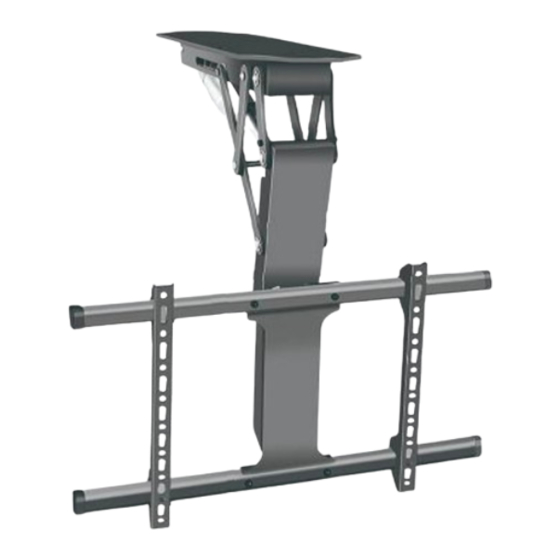
TV LIFT
USER MANUAL
MODEL: DT500-A
We continue to be committed to provide you tools with competitive price.
"Save Half", "Half Price" or any other similar expressions used by us only
represents an estimate of savings you might benefit from buying certain tools
with us compared to the major top brands and does not necessarily mean to cover
all categories of tools offered by us. You are kindly reminded to verify carefully
when you are placing an order with us if you are actually Saving
Half in comparison with the top major brands.
Advertisement
Table of Contents

Related Manuals for VEVOR DT500-A


Summary of Contents for VEVOR DT500-A
- Page 1 Technical Support and E-Warranty Certificate www. vevor. com/support TV LIFT USER MANUAL MODEL: DT500-A We continue to be committed to provide you tools with competitive price. "Save Half", "Half Price" or any other similar expressions used by us only represents an estimate of savings you might benefit from buying certain tools with us compared to the major top brands and does not necessarily mean to cover all categories of tools offered by us.
- Page 3 This is the original instruction, please read all manual instructions carefully before operating. VEVOR reserves a clear interpretation of our user manual. The appearance of the product shall be subject to the product you received. Please forgive us that we won't inform you again if...
-
Page 4: Correct Disposal
Warning-To reduce the risk of injury, user must read instructions manual carefully. CORRECT DISPOSAL This product is subject to the provision of european Directive 2012/19/EU. The symbol showing a wheelie bin crossed through indicates that the product requires separate refuse collection in the European Union. -
Page 5: Parts List
PARTS LIST Φ7*Φ10*60mm M7*60 Blanking Cap M5*10mm M6*30mm 6PCS 6PCS 4PCS 4PCS 8PCS M6*16mm M4*20mm M8*30mm Φ8*Φ16*1.7mm 4PCS 4PCS 4PCS 4PCS 4PCS Cylindrical Sleeve 4PCS ATTENTION 1. Please ensure that the screws and nuts are tightened during installation. For your safety, the product must be used in the specified size and weight limits. - Page 6 INSTRUCTIONS STEP 1 Power on the main body of the support and adjust it to open. Use a screwdriver to remove the four inner fixing screws, then detach the front connecting plate. Keep the screws as spares. STEP 2 Position the support wall plate, mark the hole locations, and drill the holes.
- Page 7 STEP 3 ① Insert the two beams into the two holes on the upper and lower sides of the hook, and install and fix the plugs at both ends of the beams by screws. ② Connect the upper and lower four holes of the mounting plate to the four middle holes of the beam through bolts and nuts.
- Page 8 STEP 5 Install TV As shown in the figure: Connect the 4 holes of the connecting plate connected to the TV and the holes at the front end of the main body through the spare screws removed in step 1. STEP 6 Connection adapter...
-
Page 9: System Connection
Controller Instruction Manual I. Function introduction II. System parameters Intelligent single column controller 1.Input voltage:DC29V; has the following characteristics: 2.Input current: recommending 1.It can control two motors` output above 1.8A and according to the to achieve synchronous operation; load; 2.Indicator light displays the 3.Maximum output voltage of motor fault,reseting;... - Page 10 IV. Motor interfase plug definition: V. Fault code and its treatment 1.Fault code Err1 When the manual controller shows Er1, it's a fault of Err1. It means there is something wrong with M1 interface channel (see the following picture). For exemple motors are not connected in a positive way;...
-
Page 11: System Reset
VI. System reset 1.Prompt reset When the manual controller indicator light always on (see the following picture),it means the system is resetting. The whole system needs to reset maunally. 2.Line reset When the manual controller shows the minimum heigh ,pressing "down" button more than 5 seconds and the indicator light is on. - Page 12 The colunm will rise 5~10mm after a short time when it reach the lowest point. When the manual controller indicator light is off(see the following picture),releasing the hand and end at resetting. VII. Preset target height 1.Preset target height quantity: The system provides 4 groups of preset height storage 2.Preset target height data erasure: The erasing function is not configured separately.
- Page 13 ③Within 2 seconds, press "2" before "SET" disappears ④The "S-2" preset is displayed. End, the previous display is restored. 5. Use the method of preset target height: At any height (reset state, cannot perform this operation in the wrong state), you can use keys 1-4 to quickly reach the preset target height. If the current height is already near the preset target height, no action will be performed.
-
Page 14: Product Parameters
PRODUCT PARAMETERS Safe Adapter input Loading Model Input Region voltage Weight America 100-240V~ DT500-A 88lbs DC29V 1.8A 50/60Hz Europe... - Page 16 Technical Support and E-Warranty Certificate www. vevor. com/support...
Need help?
Do you have a question about the DT500-A and is the answer not in the manual?
Questions and answers