Advertisement
Quick Links
Technical Support and E-Warranty Certificate www.vevor.com/support
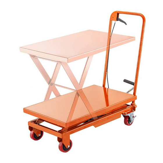
HYDRAULIC LIFT TABLE
ASSEMBLY & OPERATION
INSTRUCTIONS
We continue to be committed to provide you tools with competitive price.
"Save Half", "Half Price" or any other similar expressions used by us only represents an
estimate of savings you might benefit from buying certain tools with us compared to the major
top brands and doses not necessarily mean to cover all categories of tools offered by us. You
are kindly reminded to verify carefully when you are placing an order with us if you are
actually saving half in comparison with the top major brands.
Advertisement

Related Manuals for VEVOR TF15


Summary of Contents for VEVOR TF15
- Page 1 Technical Support and E-Warranty Certificate www.vevor.com/support HYDRAULIC LIFT TABLE ASSEMBLY & OPERATION INSTRUCTIONS We continue to be committed to provide you tools with competitive price. "Save Half", "Half Price" or any other similar expressions used by us only represents an estimate of savings you might benefit from buying certain tools with us compared to the major top brands and doses not necessarily mean to cover all categories of tools offered by us.
- Page 3 CustomerService@vevor.com This is the original instruction, please read all manual instructions carefully before operating. VEVOR reserves a clear interpretation of our user manual. The appearance of the product shall be subject to the product you received. Please forgive us that we won't inform you again if...
- Page 4 Note: Owner and Operator MUST read and understand this operating instructions before use this table truck SPECIFICATIONS Model TF15/TF23 TF50 TFD15 TFD35 TFD80 Capacity 150Kg/230Kg 500Kg 150Kg 350Kg 800Kg Maximum 720mm 900mm 1270mm 1530mm 1500mm Height Minimum 220mm 285mm 275mm...
- Page 5 manner. 9.Be sure to wear ANSI approved safety gloves when using tools or equipment. 10.Release load before service or maintenance. 11.Avoid off-center loads. Do not operate if workpiece tilts or binds during compression. 12.STOP and release compression if you suspect imminent structural failure.
- Page 6 OPERATION 1.Close the valve knob by unclenching the control handle until it stops. 2.Table is raised by activating the foot pedal. 3.To lower the table, slowly draw the control handle. 4.Before loading, and while stationary, lock the caster brake. MAINTENANCE Lubricate each friction point monthly with a good quality grease.
- Page 7 TROUBLE SHOOTING (NOTE: DO NOT ATTEMPT TO REPAIR THE TABLE TRUCK UNLESS YOU ARE TRAINED AND AUTHORIZED TO DO SO.) Trouble Clause Fixing Methods The table can not be -The set screw is not in correct -Adjust the set screw(26) up or lifted up ,while activate position ,the pump valve is opened.
- Page 8 Trouble Clause Fixing Methods The table can not be -The piston rod(pump (5)) or link -Replace the piston rod(pump (5)) lowered. assembly(2) is deformed resulting or link assembly(2). from partial loading slanting to one -Keeping the table in the lowest side or overloading.
- Page 9 HYDRAULIC LIFT TABLE PARTS Descrlption Q'ty Descrlptlon Q'ty Table Slide Lever Link Assembly Bushing Link Shaft Split Pin Link Shaft Rubber Bumper C-Clip Lift Lever C-Clip Spring Lock Washer Cylinder Shaft Bolt C-Clip Foot Lever Boller Guide Foot Lever Pad Roller Guide Handle Top Nut...
- Page 10 Descrlption Q'ty Descrlptlon Q'ty Control Handle (20) Steel Ball Cylinder Assembly (21) Cylinder Assembly Screw Cover (22) Spring (23) Bolt O-Ring (24) Hermetic Copper Nut Shove Pin Seat (25) Shove Pin (26) C-Clip Relief Plug Lock Pin (27) O-Ring (28) C-Clip Relief Spring Cylinder Lock Pin...
- Page 11 MADE IN CHINA...
- Page 12 Technical Support and E-Warranty Certificate www.vevor.com/support...
Need help?
Do you have a question about the TF15 and is the answer not in the manual?
Questions and answers
Hydraulic not lift when foot pedal pumped
Possible reasons the VEVOR TF15 hydraulic is not lifting when the foot pedal is pumped include:
1. The caster brake is not locked, causing instability.
2. There may be oil leakage from the hydraulic cylinder.
3. The hydraulic cylinder may be damaged or malfunctioning (not user-serviceable).
4. The control handle may not be in the correct position (it should not be drawn when trying to lift).
5. There may be insufficient hydraulic fluid inside the system.
Check these components for proper function and condition.
This answer is automatically generated