Advertisement
Service Overview
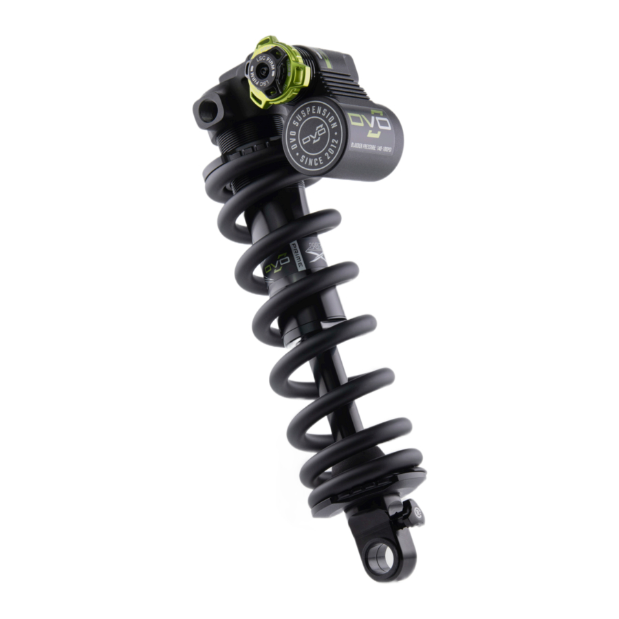
This manual will guide you step by step performing a full service to your Topaz shock. Please follow each instruction carefully to achieve the best and safest results.
*Always wear your safety gear while working on suspension products. We care about you, make sure you wear your safety glasses and protective gloves while servicing DVO Suspension Products.

ALWAYS WEAR SAFTY GEAR!
Tools Needed For Service
- Valve Core Remover
- Valve Puller
- Oil Drain Pan
- Bleed Syringe
- 24mm Crows-foot Wrench
- 16mm Socket or Crows-foot Wrench
- Flathead Screwdriver
- Vice
- 14mm Shaft Clamps
- Pick
- Shock Pump
- 2mm, 3mm, 4mm Allen Key
- Torque Wrench
- 14mm Seal Bullet (#140-M080-S)
Supplies Needed For Service
- Rebuild Kit part #191-9010
- Gloves
- Safety Glasses
- Clean, Lint Free Rag
- Suspension Cleaner or Alcohol
- Loctite 263 RED
- Loctite 243 BLUE
- 2.5 wt oil. No Maxima
- Slickoleum Grease
Recommended Service Interval
- Full Service 100 Hours of Ride Time
Lube & Torque Specs
| Lubricant | Brand | Wt. | Notes |
| Shock oil | DVO, Motul, Motorex, Silkoline, R.S.P. | 2.5 | Do NOT use Rock Shox or Maxima powersports suspension fluids under any circumstances. Permanent seal damage will occur. |
| Grease | Slickoleum, Slick Honey | - | |
| Product | Oil / Grease | Volume | Type (Wt.) |
| DVO-WP Jade X | Damper | 70-80 cc | 2.5 |
| Slickoleum, Slick Honey | N/A | 2.5 | |
| Product | Part | Torque | Notes |
| DVO-WP Jade X | Bleed screw | 2 N.m | N/A |
| Damper body end cap | 20 N.m | N/A | |
| Housing to damper body | 20 N.m | LocUte 2701 Green | |
| Reservoir housing bolts (x2) | 3 N.m | N/A | |
| Damper sha[ to eyelet | 15 N.m | LocUte 263 Red | |
| Piston group bolt | 15 N.m | LocUte 243 Blue | |
| Piston nut | 5 N.m | LocUte 243 Blue | |
| T3 lever set screw | .6 N.m | LocUte 243 Blue | |
| Valve core | .6 N.m | N/A |
The data contained in this document supersedes any and all previous lubrication, torque, and thread coat specifications. Failure to follow these specifications will void the product warranty and may lead to serious injury or death.
Damper Service
EYE HAZARD
- Rotate the spring preload collar counterclockwise to decrease tension on the spring, and remove the lower spring clip. Remove the spring and spring spacer and set aside.

- Remove the bladder cap and release the air from the bladder.

- Thread on the valve puller, and press the bladder cap inward, exposing the bladder air plug clip. Remove the valve puller. Use a small pick or flathead and gently remove the clip and set aside.

- Thread the valve puller back on, and pull up to remove the bladder. Remove the bladder cap and bladder from the valve puller and set aside, and pour the reservoir oil to a catch basin.


- (For PRO damper, proceed to step number 12)
Using a 2mm allen wrench, remove the compression knob fixing bolt.
![]()
- Remove the LSC knob and o-ring, followed by the green HSC knob.

- Carefully remove the two bearings, followed by the springs. It's often easiest to use a pick or small allen wrench to remove the springs. Be careful not to misplace the bearings and springs.

- Using an 18mm crows-foot wrench, loosen the compression unit from the housing. Unthread the unit and set aside.


- Remove the spring, and then the centering washer.

- Gently grasp the nut of the compression unit with needle nose pliers, and lift the assembly out.

- Dry and inspect the parts and proceed to step #14.

- (PRO Damper)
Loosen the comp loader cover using a 4mm allen wrench, then remove the loader using pliers and set aside.


- Remove and replace the o-ring on the compression loader cap and set aside.

- Gently clamp the shock housing in a vice with the shaft/eyelet facing up/ vertical. Use a 24mm wrench to loosen the seal head.
![]()
- Unthread and remove the shaft assembly and set aside. Drain the oil from the damper body into a catch pan.

- Use a 3mm allen wrench to remove the reservoir to housing bolts, and then remove the reservoir from the upper housing and set aside.
![]()


- Using a small pick, remove the o-ring from the upper housing. Remove the alignment pin from the reservoir as shown. Take care not to misplace!

- Clamp the damper shaft in a vice using 14mm shaft clamps. Be sure the rebound adjuster is facing outward to provide adequate clearance and prevent damage. Use a 16mm socket to loosen piston bolt.

- Remove the piston bolt group, spray clean with suspension cleaner and set aside.

- Remove the damper end cap and bottom out bumper, and discard. Your seal repair kit includes a new end cap and bumper.


- If you are servicing a new shock for the first time, you will need to remove the wax pellet from the bleed screw before it can be removed. Use a pick to remove the wax and expose the hex opening. Use a 2mm allen wrench to remove the bleed screw.

- Using suspension cleaner, spray and clean the inside of the damper body and housing and set aside.

- Disassemble, clean and inspect the piston bolt group.

- Carefully use a razor blade to cut and remove the glide ring from the piston.


- Reinstall the new glide ring by pressing it on as shown.

- Begin reassembling the piston bolt group. Ensure the washers, shims, and piston are installed in the same order in which you removed them. After reassembly set aside.

- Using small needle-nose pliers, gently grasp and remove the rebound needle. Remove and reinstall the o-ring and set aside.

- Install the shaft bullet tool (#140-M080-S) on the shaft and apply a light coat of grease. Slide the new bottom out bumper back on the shaft.


- Apply a light coat of grease to both end of the seals on the new damper end cap, slide back onto shaft, and then remove the shaft bullet.

- Rotate the rebound knob counterclockwise, so that it is in the full-open position. (Do not back the knob all the way out of the eyelet). Holding the shaft assembly vertically, push the needle into the shaft.

- Visibly check that the needle is in the open position.

- Apply a light coat of Loctite 243 Blue to the piston bolt threads and allow to cure. Clamp the damper shaft into the 14mm shaft clamps, and reinstall the piston bolt group.


- Using a 16mm socket, torque the piston bolt to 15Nm.
![]()
- Reinstall and apply a light coat of grease to the housing o-ring and centering pin, then reinstall the reservoir housing bolts. Using a 3mm allen wrench, torque to 3Nm.

- (Prime damper)
For PRO damper, proceed to step number 61) Press the HSC/LSC adjuster out of the housing.

- Remove the o-ring from the housing. Remove the o-ring from the piston.


- Remove the o-ring from the compression adjuster. Remove the o-ring from the LSC knob.

- Using a 3mm allen wrench and a 9mm socket or open wrench, loosen the piston nut. Remove the piston nut.

- Clean and inspect the piston group.

- Begin reassembly in the reverse order, ensuring the piston orientation is as shown. Apply Loctite 243 Blue to the piston nut and alloy to cure.


- Using a 3mm allen wrench, and a 9mm wrench or socket, torque the piston nut to 3N.m and set aside.
![]()
- Use 10mm and 9mm wrenches and disassemble the LSC assembly.
![]()
- With the nut removed, gently press the inner shaft from the housing, taking care to not misplace the bearing.

- Lay the parts out for cleaning and inspection.


- Remove and replace the o-rings.

- Apply a light coat of grease to the assembly including o-ring, and place bearing on spring. Slide the assembly onto the hex shaft.

- The two pieces should sit together as shown. Insert the unit into the main assembly.

- Gently press the bearing down and slide the shaft until the threads make contact. Use a small flathead screwdriver to turn and tighten the shaft in the assembly.


- Apply Loctite 243 Blue to the threads of the LSC needle cap and allow to fully cure. Thread the collard nut into the assembly.

- Make sure the LSC needle cap is completely seated. Tighten using a 9mm wrench and an 10mm socket and torque to 3Nm.

- Apply a light coat of grease the compression unit and to the inside lip of the compression cap where the adjustment rotation occurs.

- Guide the HSC/LSC unit into the compression cap, ensuring that the hex nut lines up with the internal hex recess.


- Apply a coat of grease to the piston o-ring surface. Press the piston group into the housing (it can be helpful to slightly angle the piston group).

- Place the spring centering washer over the piston group as shown, making sure the raised lip is facing up. Next place and center the spring in place.

- Remove and replace the o-rings on the compression cap, and apply a light coat of grease.

- Insert the compression cap assembly into the housing, and start thread engagement by hand. Once threads are engaged, tighten to 5N.m using an 18mm crows-foot wrench.


- Insert the detent springs back into the cap. Apply a light coat of grease to the tops of the springs and holes, and place the bearings on top of the springs. The grease will hold the bearings in place.

- Apply a coat of grease to the underside of the green HSC knob and press onto the HSC hex.

- Apply a light coat of grease to the bottom of the LSC knob and o-ring. Apply Loctite 243 Blue to the compression knob bolt and allow to fully cure.

- After the thread lock has cured, reinstall the bolt using a 2mm allen wrench and torque to 1 Nm. The PRIME compression service is complete; move to step 68 to complete the Jade X service.
![]()


- Place a 3mm allen key into the end nut of the compression loader and push the needle out.

- Replace the o-ring on the compression needle and place it back into the loader. The pointed end of the needle goes in first.

- Remove and replace the upper and lower o-rings on the loader.

- Apply a generous amount of grease to the end of the loader as shown. Make sure the needle is flush with the bottom of the loader before installing.


- Apply a thin layer of grease to the o-rings on the loader and the inside of the reservoir, and place the loader in the reservoir.

- Move the T3 compression switch to the open position as shown.
![]()
- Insert a 3 mm allen key into the compression loader and push downward. You should feel a "click". Reinstall the loader cover and torque to 3N.m with a 4mm allen wrench.

- Reinstall the bleed screw into the housing. Next, apply a light coating of grease to the bladder and bladder cap, coating the edges all the way around.


- Over your catch basin, fill the bladder reservoir with oil. Slowly press the bladder back into the reservoir (oil will overflow).

- Install the valve puller and press the bladder cap into the reservoir enough to expose the clip groove. Remove the valve puller and reinstall the retaining clip.
Note: When pressing the bladder in, ensure that the bladder remains straight and even.

- Reinstall the valve puller and pull the bladder plug up until it locks into place.
![]()
- Fix the housing in a vice with the damper body upward and fill to the top with 2.5wt suspension oil. Slowly insert the shaft assembly into the damper body. Oil will overflow and that is acceptable.
![]()


Damper Bleed
- Thread the damper end cap in and then torque to 20Nm. using a 24mm crowsfoot wrench.
![]()
- Fix the shock in the vice in an upright, angled position as shown, and remove the bleed screw.

- Thread the bleed syringe into the bleed port, and fill half of the the cylinder with 2.5wt suspension oil. Cycle the shock up and down to remove any air bubbles trapped in the system.
![]()
- After the bleed process is completed, remove and replace the o-ring on the old bleed screw, or install a new bleed screw and torque to 3N.m using a 3mm allen wrench.


- Using a shock pump, inflate the bladder to your desired pressure. Suggested range is 140-180PSI. Do not exceed 180psi.
![]()
- Reinstall the bladder air cap and then reinstall the spring preload collar and spring spacer, followed by the spring.
Note: Not all configurations require the use of a spring spacer.

- Guide the spring clip into place, and then slightly compress the spring while pressing down on the clip so that it fully seats on the eyelet base.

- Wipe down the shock and reinstall on the bike according to the bike manufacturer specifications.
![]()


Spare Parts

Rebuild Kit Contents

| ITEM NO. | PART NUMBER | DESCRIPTION | D191-9010 |
| 1 | DVO1421015 | END CAP | 1 |
| 2 | RAA 095 | END CAP DUST SEAL | 1 |
| 3 | REE112 | 14MM BUSHING | 1 |
| 4 | RAA 096 | END CAP SEAL | 1 |
| 5 | FAA256 | END CAP O-RING | 1 |
| 6 | FAA349 | END CAP O-RING | 1 |
| 7 | FAA135 | REBOUND NEEDLE O-RING | 1 |
| 8 | D191-1005 | BLADDER | 1 |
| 9 | DVO1561048 | BLADDER AIR VALVE PLUG | 1 |
| 10 | FAA149 | DAMPER END CAP O-RING | 1 |
| 11 | FAA170 | VALVE CORE | 1 |
| 12 | DVO1421014 | BUMPER | 1 |
| 13 | RAA141 | COMPRESSION CAP O-RING | 1 |
| 14 | REE253 | HOUSING TO RESERVIOR DOWEL PIN | 1 |
| 15 | RSB024 | HOUSING TO RESERVIOR BOLT | 2 |
| 16 | DVO1561049 | BLADDER AIR PLUG CLIP | 1 |
| 17 | FAA234 | COMPRESSION BASE O-RING | 1 |
| 18 | RAA121 | COMPRESSION NEEDLE O-RING | 1 |
| 19 | RAA090 | GLIDE RING | 1 |
| 22 | FAA175 | HOUSING TO RESERVIOR O-RING | 1 |
| 23 | RAA118 | COMPRESSION PISTON O-RING | 1 |
Contents of the rebuild kit subject to change without notice based on product changes or improvements.
Safety Information
Failure to comply with these warnings and instructions may cause SERIOUS INJURY, DEATH, or DAMAGE TO YOUR PRODUCT.
Be sure to read this manual carefully before using your DVO suspension. Throughout this manual, reference is made that "an accident" could occur. Any accident may cause damage to the product, SERIOUS INJURY, OR DEATH.
These instructions contain important information about the correct installation, guidelines for setup, service and maintenance of your suspension. Nevertheless, please be informed that special knowledge and tools are essential to install, service and to maintain DVO Suspension. Common mechanical knowledge may not be sufficient to repair, service or maintain your suspension. Therefore we strongly recommend getting your suspension installed, serviced and/or maintained by a trained and qualified bicycle mechanic. Improper installation, service or maintenance can result in an accident.
Forks and rear shocks contain fluids and air under extreme pressure. DO NOT attempt to disassemble any portion of a DVO Suspension product unless instructed to do so by a DVO Suspension authorized technician.
Only use genuine DVO Suspension replacement parts. Modification, improper service, or the use of aftermarket replacement or spare parts may result in an accident and VOIDS the warranty of your product.
DVO Suspension forks and rear shocks are designed for the usage by a single rider only.
DO NOT use DVO Suspension products on any powered vehicle that is not a pedal-assist Class-1 or Class-3 e Bike.
Always be equipped with proper safety gear. This includes a properly fitted and fastened helmet. According to your riding style you should use additional safety protection. Make sure your equipment is in flawless condition.
Make sure you select the correct fork and rear shock according to your frame manufacturer specification. Installing suspension that does not match the geometry of your frame could result in a failure of the suspension itself and void the suspension warranty. Installing a fork or rear shock not designed for your frame will change the geometry and handling of your bike. Learn how to ride and train your skills. Know your limits and never ride beyond those.
Study all other manuals provided with your bicycle and make yourself familiar with all components mounted to your bike.
PRE-RIDE SAFETY CHECK
- DO NOT ride your bicycle if any one of the following test criteria is not passed! Riding your bike without eliminating any defect or carrying out the necessary adjustments can result in an accident, SERIOUS INJURY OR DEATH.
- Do you notice any cracks, dents, bent, or tarnished parts of your suspension fork or shock, or any other part of your bicycle? If so, please contact a trained and qualified bicycle mechanic to check your fork, shock, seat post, saddle, and complete bike.
- Do you notice any oil leaking from your fork and/or shock? If so, please consult a trained and qualified bicycle mechanic to check your suspension and bike before riding.
- Make sure your wheel is attached and centered properly in order to avoid any contact with the suspension fork or brake system.
- Make sure your axle system is secure. There should be no play between the hub and fork lower.
- Make sure your brakes are properly installed, adjusted, and work properly. This also applies to every other part of your bike like handlebars, pedals, cranks arms, seat post, saddle, etc.
- Check the cable length and routing of your braking components. Make sure they do not interfere with your steering actions or full compression and extension of your suspension.
- Check your shock hardware and ensure there is no play between the shock and mounting surfaces. Ensure your shock hardware is tightened to the bike manufacturer's recommend torque before riding.
Documents / ResourcesDownload manual
Here you can download full pdf version of manual, it may contain additional safety instructions, warranty information, FCC rules, etc.
Advertisement


Need help?
Do you have a question about the JADE X Series and is the answer not in the manual?
Questions and answers