Advertisement
- 1 Preface
- 2 Product Overview
- 3 Installation Instructions
- 4 Operating Instructions
- 5 Electric Control System
- 6 Battery Charging and Charger Usage
- 7 Maintenance
- 8 Transportation and Storage
- 9 Documents / Resources
Preface
Please read this manual carefully before using the RHINO 1000 Electric Outboard.
If you carefully follow these instructions, you will be able to:
- Avoid danger and injury.
- Save maintenance costs and reduce downtime.
- Increase the reliability and service life of the system.
Symbols

Danger: Situations where death or serious injury may occur due to failure to follow instructions.

Warning: Situations where moderate or minor injury, or damage to property may occur due to failure to follow instructions.

Reminder: Useful information or tips.
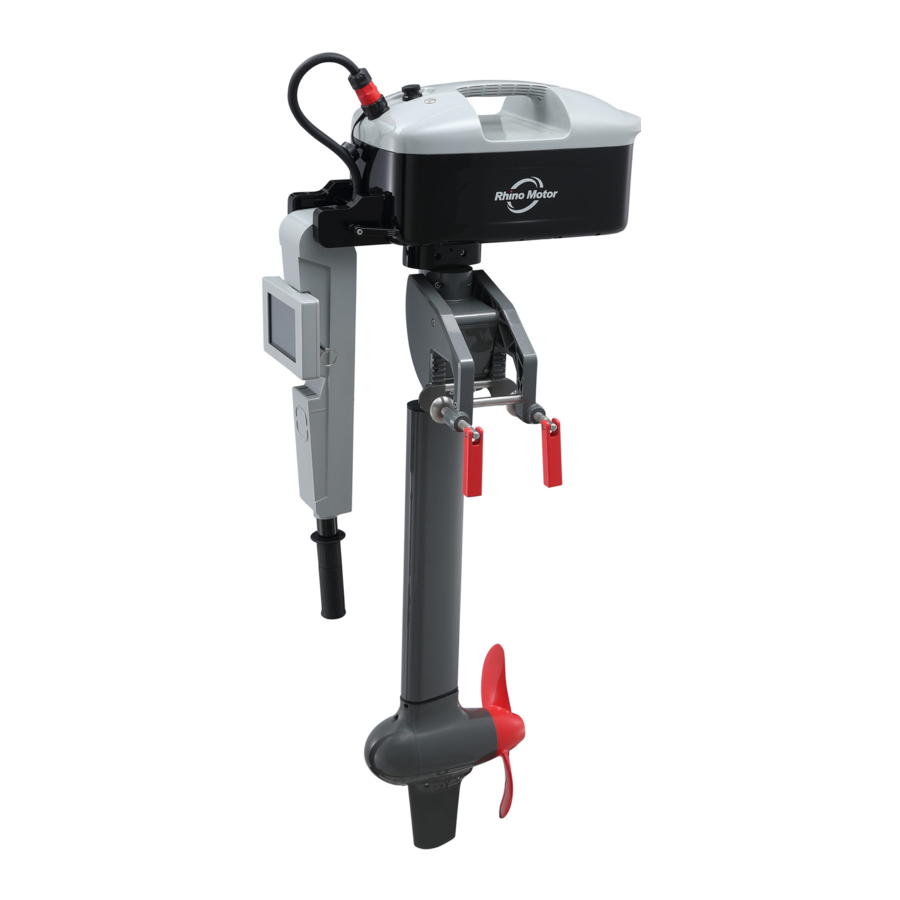
Product Overview
Names of system main components

Figure 1-1
Specifications
| Outboard Main Engine | Main Engine Model | RHINO1000 |
| Input power | 1kW | |
| Rated current | 20A | |
| Equivalent gasoline engine propulsion power | 65Lbs(3Hp) | |
| Rated speed of the electric motor | 1200rpm | |
| Electric motor maximum efficiency | 92% | |
| The highest efficiency of the whole machine | 55% | |
| Shaft Length | 750mm | |
| Weight | 18kg | |
| Size(Length*Width*Thickness) | 1250*830*220mm | |
| Propeller diameter/pitch | 11"/5.6" | |
| Trim angle adjustment | 0°、9.5°、19°、28.5°、38°、47.5°、89° | |
| Battery | Battery model | 4825Li |
| Battery type | Ternary lithium | |
| Rated capacity | 1440Wh | |
| Rated voltage | 48V | |
| Combination method | 13S6P | |
| Maximum charging current | 12 A (10~35℃) | |
| Maximum discharge current | 30A | |
| Charge cut-off voltage | 54.6V | |
| Discharge cut-off voltage | 36.4V | |
| Charging time | 8 Hours(54.6V/3A)/ 3 Hours (Fast) | |
| Battery weight | 8.4KG | |
| Size | 340*170*200mm | |
| Use and storage temperature (environment) | Charge: 0℃~45℃ Discharge:-20℃~55℃ Storage:-10℃~35℃ | |
| Battery Charger | Charger model | XSG5463000 |
| Rated Power | 163.8W | |
| Output Voltage | 54.6V | |
| Output current | 3.0A | |
| Charge termination current |  0.3A 0.3A | |
| Rated input voltage (frequency) | 100~240V(50/60Hz) | |
| Maximum input current | 1.9A@220V | |
| Operating and storage temperature (environment) | working:-10℃~45℃ storage:-30℃~70℃ | |
| Efficiency |  87% 87% | |
| Weight | 0.72kg |
Packing list
| Number | Name | Quantity |
| 1 | Electric outboard main unit | 1 |
| 2 | Battery pack | 1 |
| 3 | Charger | 1 |
| 4 | User manual | 1 |
| 5 | quality certificate | 1 |
Please keep it properly for convenient use, inquiry, and maintenance
Installation Instructions
Installing the outboard onto the boat
- Use the electric outboard main unit to hang on the transom mounting plate. Refer to Figure 2-1.
![]()
Figure 2-1 - Rotate the small red handle of the locking clamp to tighten the bolts. Refer to Figure 2-2
![]()
Figure 2-2 - Check whether the outboard motor is securely installed


If using a single outboard motor, please fix the main unit at the center line position of the boat hull.
If using two or more outboard motors, the distance between the outboard motors should be no less than 600mm.
Install the battery onto the outboard
- Lift the battery, align the front of the battery with the mounting holes of the main unit base, and lower it. Refer to Figure 2-3.

Figure 2-3 - Rotate the hex head screw of Battery base at the bottom until the battery is fixed in a horizontal position. Refer to Figure 2-4.

Figure 2-4 - Confirm whether the battery pack is securely installed.


When installing the battery pack, be sure to hold the battery firmly to prevent it from slipping.
Do not place the cables under the battery pack.
Install the control handle
- Insert the front part of the control handle into the middle of the Battery base, as shown in Figure 2-5,

Figure 2-5
aligning the alignment mark, the red part in Figure 2-6. Insert the base pivot axis into the base hole and tighten the thread clockwise.
![]()
Figure 2-6 - Rock the control handle to confirm that it is securely installed.


When installing the control handle be sure to grip it tightly to prevent it from slipping. Please do not fold or squeeze the control cable of the handle.
Connection cables
- Connect the motor cable to the battery socket on the battery pack, aligning it with the positioning groove on the socket, and rotate it clockwise to lock the cable. Refer to Figure 2-7.

Figure 2-7 - Connect the handle cable to the handle socket under the outboard handle, align the positioning groove of the socket, rotate clockwise, and lock the cable. Refer to figure 2-8.

Figure 2-8 - After the cable connection is completed, please gently shake, and pull out to confirm if the connection is secure.


When connecting the cables, please align with the positioning holes and avoid applying excessive force. Keep the inside of the plug and socket dry. After installation, always check whether the components are firmly secured.
Operating Instructions
- Ensure that the outboard motor is locked tightly.
- Ensure that the cables are free from damage.
- Ensure that the battery is securely installed.
- Ensure that the propeller is in the stopped position.
- Ensure that all personnel on board are wearing life jackets.
- Check that the throttle handle rotates smoothly.
- Check that the battery has sufficient charge.
- Check that the throttle is in the 'N' position.
Start the outboard motor
Place the safety switch in the designated position on the handle, as shown in Figure 3-1,

and press the power switch on top of the battery pack, as shown in Figure 3-3.

Figure 3-3
The battery indicator light will turn on, and after the system self-checks, the battery system will supply power to the propulsion system, and the touch screen will light up.
The battery system has a malfunction, and the fault light is on.
 Securely always attach the safety switch lanyard to your wrist or life jacket.
Do not place magnetic objects near the safety switch's dedicated position on the handle.
Test run of the outboard
Gently rotate the throttle handle to confirm that forward/reverse is functioning properly, as shown in Figures 3-4 and 3-5.

Turn the control handle to the left and right to confirm that the boat is turning in the correct direction.
Only after confirming that the entire system is functioning properly and securely should you proceed with full-speed operation.
When the handle is pushed to the right, the boat turns left; when the handle is pushed to the left, the boat turns right. Keep the handle straight and still to move the boat forward.
 Between switching from forward to reverse, or vice versa, move the handle to the neutral position ('N'), bring the boat to a stop, and then switch to the opposite direction.
Outboard stopping method
- Rotate the throttle handle to the neutral position ('N'). Figure 3-6
![]()
Figure 3-6 - Unplug the safety switch. Figure 3-7

Figure 3-7 - Press and hold the battery power switch 'POWER' until the power is cut off. Figure 3-8
![]()
Figure 3-8


Propeller lift method
When the boat needs to be docked or debris such as water plants need to be cleared, the propeller needs to be lifted.
- Grip the machine by hand, pull out the Pitch Wrench from the hole, and lift it up, as shown in Figure 3-9.

Figure 3-9 - Slowly lower the machine to the raised angle (angle with the transom angle of about 89°), then press down the Pitch Wrench to the corresponding hole, as shown in Figure 3-10.
![]()
Figure 3-10 - To lower the motor, pull the pitch wrench again and slowly lower the motor back to its original position.


The tilting function should only be operated when the entire system is in a stopped state.
Pitch angle of propeller blades adjustment
The RHINO 1000 electric outboard has eight adjustable pitch angles: 0°, 9.5°, 19°, 28.5°, 38°, 47.5°, and 89° (see Figure 3-11).

Figure 3-11
During normal use, adjust the pitch angle to an appropriate position according to the actual situation.
Manipulation is only allowed when the equipment is in a stopped state.
When operating, please slowly raise or lower the pitch angle.
Operation steps
- Raise the outboard motor to the highest position at 89°, as shown in Figure 3-12.
![]()
Figure 3-12 - Pull out the Pitch Wrench, as shown in Figure 3-13.
![]()
Figure 3-13 - Lower the outboard to the desired pitch angle and then press down the propeller pitch wrench to the upper position, as shown in Figure 3-14.
![]()
Figure 3-14 - Lower the outboard motor to complete the pitch angle adjustment, as shown in Figure 3-15.
![]()
Figure 3-15


When increasing speed, it is necessary to always observe the water flow at the stern of the boat. If abnormal water flow (such as cavitation) occurs, please stop the machine immediately and raise the outboard motor.
Beaching mode setting
When a boat with an outboard motor navigates in shallow waters with complex underwater conditions, collisions or entanglement with underwater plants may occur, which can interfere with the normal operation of the outboard motor and even damage it. Before navigating in waters with complex or unclear underwater conditions, the outboard motor can be set to beaching mode to protect the outboard motor and operators. When set to beaching mode, the outboard motor can automatically tilt in the opposite direction of the forward direction after a collision, cushioning the impact and reducing damage.
As shown in Figure 3-16, pull the Pitch Wrench outward from the hole, then move the pitch wrench to the lowest position and then press to complete the setting. To cancel the beaching mode, pull the pull the Pitch Wrench outward from the hole, then move the pitch wrench to the fully up position and press to the hole to cancel the beach mode.

Figure 3-16
Reverse gears are prohibited in beaching mode, otherwise it poses a certain safety hazard.
Be sure to set and cancel the beach mode while the engine is in the stopped state.
Under normal circumstances, it is generally not necessary to set the outboard motor to beach mode. Beach mode should be considered when navigating in complex environments with underwater obstacles such as dense vegetation, reefs, or shallow water.
Horizontal lock method of control handle
To fix the running direction of the boat, you can horizontally lock the control handle. As shown in Figure 3-17, insert the positioning pin into the hole shown in the diagram. When the positioning pin is inserted, the operating handle cannot be horizontally rotated. To cancel the lock mode, you can only pull out the position pin.

Figure 3-17
It is necessary to set and cancel the fixed running direction mode while the outboard motor is in the stopped state.
Vertical adjustment method of control handle
The control handle can be adjusted in the upward, and downward directions for user convenience.
Raise the handle, as shown in Figure 3-18:

Figure 3-18
Fold up the handle, as shown in Figure 3-19:

Figure 3-19
Pull the handle to the left with force until it reaches its limit position, then push it down.
Fold down the handle for easy storage and transportation.
Electric Control System
RHINO 1000 electric outboard motors are equipped with intelligent control electrical systems, which perfectly realize functions such as throttle control, safety checks, battery information interaction and
GPS positioning.
System power-up
Touch the power switch lightly, the indicator light will light up. After the battery system self-test is completed, the electrical system will start to supply power, as shown in Figure 4-1.

Figure 4-1
The outboard should be securely fixed, and the battery should be tightly installed.
Ensure that the cable connections are secure, and that the operator is wearing a life jacket.
Ensure the stability of the boat.
Please read the user manual carefully and familiarize yourself with the operating procedures.
Touch screen
User can choose "Manual" or "Smart" operation interface from the bottom tabs on the touch screen.
Manual interface

Figure 4-2
The Icons on the screen are explained as followings.
| Number | Screen Icon | Explanation |
| 1 |  | Display real-time power consumption |
| 2 |  | The Bluetooth icon is displayed when a Bluetooth device is connected. |
| 3 |  | The GPS icon will be displayed after the GPS device has successfully positioned |
| 4 |  | The safety switch icon will be displayed when the safety switch is in place. If the safety switch is not in place, the system cannot be started. |
| 5 |  | The bracelet icon will be displayed when a bracelet device is detected. |
| 6 |  | This is a description of the system status display. "F" represents the propulsion system pushing the boat forward, "R" represents the propulsion system pushing the boat backward, "N" represents the system being shut down. 1, 2, 3, 4 represent the actual operating speed gears of the system. |
| 7 |  | As the battery management system (BMS) status display, 27% in the figure represents the accurate state of charge (SOC) value. |
| 8 |  | This is the display for the boat's system speed. Unit: knots |
| 9 |  | This is the display of the battery system output power during actual operation |
| 10 |  | Remaining runtime or mileage (optional). |
| 11 |  | Cumulative mileage of this trip. |
| 12 |  | When a temperature alarm is detected in the BMS or the drive system, this image will be displayed along with the message 'Please get professional maintenance technicians'. |
| 13 |  | When there is a system fault alarm, this image will be displayed. It will also display the message 'please get professional maintenance technicians. |
| 14 |  | When the system is powered on for the first time, if the throttle handle is not in the '0' position, the handle icon and reset icon will be displayed, and display 'Please Reset'. After the throttle handle returns to the '0' position, the handle icon will disappear. Press reset icon and then the user could operate the throttle handle again. |
| 15 |  |  When the SOC is detected to be lower than 20%, the red battery icon and reset icon will be displayed, and also "Please reset" will be displayed. The user can reset and continue to operate at low speed. When the SOC is detected to be lower than 20%, the red battery icon and reset icon will be displayed, and also "Please reset" will be displayed. The user can reset and continue to operate at low speed. |
When there is a fault, please operate with caution to ensure personal safety.
Smart Interface

Figure 4-3
The RHINO 1000 electric outboard motor is equipped with an intelligent operating mode: in the Smart interface, the operator selects either Speed or Range (only one option can be selected). After the selection is completed, the system selects the corresponding mileage and speed based on the battery level to ensure that it meets the operational needs of the user.
Once this function is enabled, the throttle mode on the handle will be disabled, and the system will automatically determine the speed and mileage.
This mode can reduce the tediousness of frequent throttle operation for the operator.
With the 3.7 directional lock mode, simple autopilot functions can be achieved.
Please set it when the boat is stopped.
Please ensure that the operator is wearing a life jacket and seated properly in their seat.
Please ensure that the safety switch is properly connected to the wrist or life jacket.
Please read the user manual carefully and familiarize yourself with the operating procedures.

Figure 4-4
On the Smart page, click on the highlighted area within the Speed or Range box, and the highlighting will disappear, indicating that the Smart mode has been exited and switched to the handle throttle mode.
Throttle operation
While in operation, rotating the throttle handle can adjust the throttle size. The 'N' position in the middle indicates the stop state, as shown in figure 4-5
 .
.
Figure 4-5
Turning the handle counterclockwise accelerates forward, and turning it clockwise accelerates backward (facing the handle direction), as shown in figure 4-6.

Figure 4-6
When increasing the throttle, please ask the operator to sit firmly in their seat. Please ensure that the safety switch is connected to the wrist or life jacket.
Battery Charging and Charger Usage
When the battery level is low, the battery needs to be charged. The battery system supports 'charging while using'.
It is recommended to remove the battery from the main unit before charging.
Remove battery
As shown in Figure 5-1, rotate the Motor cable connector counterclockwise and unplug the battery output cable from the main unit.

Figure 5-1
As shown in Figure 5.2, rotate the rear Hex head screw counterclockwise to loosen the base, grip the battery handle firmly, and remove the battery.

Figure 5-2
Charging
As shown in Figure 5-3, connect the charger to the plug and the Battery charging port respectively for charging.

Figure 5-3
The charger and the battery indicator light characteristics during charging are explained as the following table.
Charger output characteristics
| Charging status | Charging stage | Output current (A) | Output voltage (V) | Indicator light |
| Charging | Constant current | 3A±0.2A | 32.5V-54.6V | Red |
| Constant voltage | 3A >0.3A | 54.6V±3% | Red | |
| Fully charged | Trickle current | 0.3A >0 | 54.6V | Green |
Battery indicator light status during charging
| Battery level | Green indicator light 1 | Green indicator light 2 | Red indicator light |
| SOC≤10% | off | off | off |
| 10%≤SOC≤80% | on | off | off |
| 80%≤SOC | on | on | off |
| Malfunction | off | off | on |
Maintenance
Routine maintenance of outboard
- Keep it clean, after each use please lift the outboard out of the water.
- After use in seawater or poor water quality, please lift the outboard motor and rinse it clean with fresh water.
- Avoid contact of plugs, connectors, switches, etc. with water.
- Regularly check and replace sacrificial anode zinc blocks.
- Regularly replace the propeller shaft seal.
- Do not rotate the outboard motor when the propeller is out of the water. In a dry state, the propeller shaft seal is prone to damage and can cause water leakage.
- When shifting between forward and reverse, pause in neutral gear until the propeller stops turning before engaging the next gear.
- The entire machine meets the IP67 waterproof requirements (no damage when submerged in 1 meter of water for 30 minutes). Submerging the machine in water deeper than 1 meter or for too long can cause water damage。
- The propeller part meets the IP68 waterproof requirements (no damage when immersed in 1 meter of water for a long time).
Lithium battery daily maintenance
- To extend the battery life, please avoid prolonged exposure to sunlight and high temperature environments.
- If the lithium battery is not used for a long time, please press and hold the power button for more than 5 seconds to turn off the battery.
- If the battery is not used for six months, please charge it to 50% before storage; if the battery is not used for one year, please charge it to 100% before storage; if the battery is stored for more than one year, please check the battery level every 12 months to prevent discharge. Before storing a lithium battery, please make sure it is turned off (press and hold the power button for more than 5 seconds until the power indicator goes off).
- It is recommended to recharge the battery immediately after each use, regardless of how much power is remaining, to prevent over-discharging and damaging the battery.
- Please use a dedicated lithium-ion battery charger during charging.
- Do not throw the battery into fire or a heater.
- Do not hit, throw, or step on the battery.
- Do not directly solder or puncture the battery with nails or other sharp objects.
- Prohibited to connect two or more batteries in parallel or series for use!!!
- If the battery emits an odor, heats up, changes color, deforms, or exhibits any abnormalities during use, storage, or charging, immediately remove the battery from the device or charger and stop using it.
- Used batteries should be wrapped with insulating paper to prevent fire or explosion.
- If the battery leaks and the electrolyte enter the eyes, do not rub them. Rinse the eyes with water immediately and seek medical attention, as it can cause eye injury.
Replace or repair propeller
At any time when inspecting, removing, or installing the propeller, please make sure to disconnect the outboard motor power to prevent it from accidentally starting up. Otherwise, it may cause serious injury to the operator or nearby individuals.
Do not touch the propeller directly with your hands during operation. It is recommended to wear protective gloves to prevent injury.
The inspection steps for the propeller are as follows:
- Inspect the wear and corrosion of the propeller blades.
- Check for damage to the propeller mounting shaft and holes, and for wear of the drive pin.
- Remove any debris wrapped around the propeller, such as fishing nets, fishing lines, and water plants.
Figure 6-1 shows an installation diagram of the propeller. To remove the propeller, follow the reverse steps of the diagram.

Figure 6-1
Replace sacrificial anode zinc block
Always observe the corrosion condition of the sacrificial zinc anode block. If the corrosion is severe, it should be replaced in a timely manner to protect the electric outboard motor. See figure 62, figure 6-3, and figure 6-4.

Replace the stern fin
There are 4 steps to replace the stern fin which shown in Figure 6-5

Figure 6-5
- Loosen the Fin screws on both sides of the Stern fin, there are a total of 4 screws.
- Remove the Stern fin.
- Insert the new Stern fin.
- Secure the stern fin with two Fin screws on each side.
Maintain the touch screen
- Lift the control handle and unplug the screen kit cable connector located underneath the handle, as shown in Figure 6-7.
![]()
Figure 6-7 - Rotate the Screen kit screw counter clockwise, pull out the Screen kit pull ring , and lift the screen upwards, as shown in Figure 6-8.

Figure 6-8


Transportation and Storage
Transportation
During long-distance transportation, it is recommended to use the original packaging of the equipment as much as possible. If the original packaging is damaged, it must be secured and protected against collisions.
The equipment should be placed on a flat surface, with sufficient thickness and width of pearl cotton or foam padding at the bottom of the machine to prevent rolling or sliding during transportation, to avoid damage to the outboard motor and other injuries to people or cargo due to inadequate fixation.
For transportation, it is recommended to use the packaging methods shown in Figure 7-1

Figure 7-1 Packaging method for transporting the main engine
and Figure 7-2:

Figure 7-2. Packaging method for transporting battery
- Battery transportation must comply with relevant regulations in the user's country or region.
- It is strictly prohibited to subject battery to violent impacts or collisions.
- Damaged battery must not be transported.
- The protective outer casing of the battery must not be removed to transport the exposed battery core.
- It is strictly prohibited to transport sharp objects together with batteries during transportation.
Storage of outboard motor main unit
If the user needs to store the outboard motor main unit for a long time (more than a month), the main unit needs to be thoroughly cleaned, and any seawater or debris on the exterior should be cleaned to prevent corrosion or damage caused by seawater or debris.
Place sufficient desiccant inside the packaging box.
Ensure that the main unit is placed flat and there is no localized force.
After packaging, please place it in a dry and ventilated environment, and avoid direct sunlight.
Storage of the Outboard Battery
The storage voltage of the battery should be between 46.8V to 49.4V, and it is recommended to charge and discharge the battery every 3 months.
Do not store the battery in areas with strong static electricity or strong magnetic fields, as it may damage the battery's safety protection device and cause safety hazards.
Do not store the battery together with metal objects such as hairpins or necklaces.
When storing the battery for a long time, it should be placed in a space with good air circulation that is moisture-proof, corrosion-resistant, and dust-proof, with a relative humidity not exceeding 80% and a temperature between 0℃ and 45℃. A long-term storage temperature above 45℃ will have a corresponding impact on the service life of the lithium battery.
Avoid direct sunlight.
Website: https://rhinomotor.ca/
Customer service phone number: +1-226-577-6908
E-mail: support@rhinomotor.ca
Documents / Resources
References
Download manual
Here you can download full pdf version of manual, it may contain additional safety instructions, warranty information, FCC rules, etc.
Advertisement


Need help?
Do you have a question about the 1000 and is the answer not in the manual?
Questions and answers