Table of Contents
Advertisement
Quick Links
OPERATOR'S MANUAL
Model: FXA7141A
24V 305MM DUAL BEVEL SLIDING COMPOUND
MITER SAW
WARNING: To reduce the risk of injury, the user must read and understand the
Owner's Manual before using this product. Save these instructions for future reference.
Please contact FLEX customer service in Australia 1300 000 346 or
New Zealand 0508 000 346 any time you have questions or warranty claims.
Advertisement
Table of Contents

Related Manuals for Flex FXA7141A


Summary of Contents for Flex FXA7141A
- Page 1 WARNING: To reduce the risk of injury, the user must read and understand the Owner’s Manual before using this product. Save these instructions for future reference. Please contact FLEX customer service in Australia 1300 000 346 or New Zealand 0508 000 346 any time you have questions or warranty claims.
-
Page 2: Safety Symbols
SAFETY SYMBOLS The purpose of safety symbols is to attract your attention to possible dangers. The safety symbols and the explanations with them deserve your careful attention and understanding. The symbol warnings do not, by themselves, eliminate any danger. The instructions and warnings they give are no substitutes for proper accident prevention measures. -
Page 3: Important Safety Warnings
IMPORTANT SAFETY WARNINGS WARNING Read all safety warnings, instructions, illustrations and specifications provided with this power tool. Failure to follow all instructions listed below may result in electric shock, fire and/or serious injury. SAVE ALL WARNINGS AND INSTRUCTIONS FOR FUTURE REFERENCE. The term “power tool”... - Page 4 Do not let familiarity gained from frequent Battery tool use and care use of tools allow you to become Recharge only with the charger specified by complacent and ignore tool safety the manufacturer. A charger that is suitable for principles. A careless action can cause severe one type of battery pack may create a risk of injury within a fraction of a second.
- Page 5 SAFETY WARNINGS FOR MITER SAW Miter saws are intended to cut wood or fence. Always make certain that there • wood-like products, they cannot be used is no gap between the workpiece, fence and table along the line of the cut. Bent with abrasive cut-off wheels for cutting or warped workpieces can twist or shift and ferrous material such as bars, rods, studs,...
-
Page 6: Additional Safety Rules
cut-off piece. Reaching with your hand near Always use a clamp or a fixture designed • the coasting blade is dangerous. to properly support round material such as rods or tubing. Rods have a tendency to roll Hold the handle firmly when making an •... -
Page 7: Electrical Requirements
ELECTRICAL REQUIREMENTS Electric brake Your saw is equipped with an automatic electric brake which is designed to stop the blade from spinning in about five (5) seconds after you release the trigger switch. It is useful when making certain cuts in wood where a coasting blade would result in a wide, imprecise cut. - Page 8 SYMBOLS IMPORTANT: Some of the following symbols may be used on your tool. Please study them and learn their meaning. Proper interpretation of these symbols will allow you to operate the tool better and safer. Symbol Name Designation/Explanation Volts Voltage Amperes Current Hertz...
- Page 9 Symbol Name Designation/Explanation Wear eye protection symbol Alerts user to wear eye protection The area between the marked lines on the left and right side of the base. This zone is No-Hands Zone identified by the No-Hands Zone symbols inside the lines marked on the base. Warning symbol Do not stare at operating lamp Wear ear protection symbol...
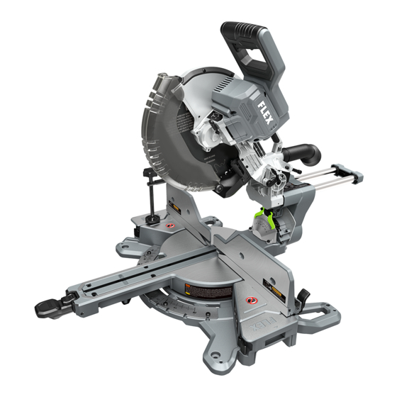
- Page 10 FUNCTIONAL DESCRIPTIONS AND SPECIFICATIONS Dual Bevel Sliding Compound Miter Saw Fig. 1 Main Handle Upper Blade Guard LED Shadow Light Head Assembly Lower Blade Guard Lock Pin Sliding Fences Bevel-lock Lever Table Extension Bevel Scale Table Table Extension Lock Lever Base Table Extension Miter-detent...
-
Page 11: Cutting Capacities
Model No. FXA7141A Rated Voltage 24V d. c. No-load Speed 4000 /min (RPM) Blade Diameter 305 mm Blade Arbor Hole Diameter 25.4 mm Max. Miter Angle 60° right, 52° left Max. Bevel Angle 48° right, 48° left Recommended Operating Temperature -20 –... - Page 12 UNPACKING Unpacking the Miter Saw When removing this tool from the box, reach down for the two carry-handles located on each end of the saw base and slowly lift the tool out of the box. WARNING To avoid severe pinching, never lift or move this saw by gripping any moving or sliding component of the saw.
- Page 13 ASSEMBLY Fig. 2 WARNING Detach the battery pack from the tool before Battery-release performing any assembly or adjustments, or Button changing accessories. Such preventive safety measures reduce the risk of starting the tool accidentally. TO ATTACH/DETACH Battery BATTERY PACK (FIG. 2) Pack To attach the battery pack: Align the raised rib on the battery pack with the...
- Page 14 Fig. 3 ALLEN KEY STORAGE (FIG. 3) There is a storage location on the saw to store the Allen key. When not in use, store the Allen key as shown in the Fig. 3 to prevent it from being lost. TO REMOVE OR INSTALL THE BLADE Fig.
- Page 15 Fig. 4d e. Raise the lower guard by hand far enough to Saw Blade access the blade bolt. Outer Inner f. Use the Allen key to remove the blade bolt by Washer Washer turning the key clockwise (Fig. 4c). NOTE: The blade bolt has left-hand threads. g.
- Page 16 Fig. 5b After the dust bag is 2/3 to 3/4 full, remove it from the saw. Bring the bag to a proper container and pull open the zipper located on the bottom of the bag. Hold the bag by the Vacuum coupler end and shake it vigorously until all the Adapter...
-
Page 17: Depth-Of-Cut Adjustment
Fig. 7 SLIDE-RAIL LOCK KNOB (FIG. 7) The slide-rail lock knob is located on the rear of the sliding mechanism. When engaged, it locks the system in either the full forward or the full back position and Slide-rail prevents movement while transporting the saw. Lock Knob When held in the full back position, the saw is more compact for lifting and storage. -
Page 18: Calibrating Miter Detent System
Fig. 9a CALIBRATING MITER DETENT SYSTEM (FIG. 9a & 9b) a. Engage the miter detent at the 0° position. b. Loosen the four miter scale screws in the miter scale plate by using the supplied Allen key (Fig. 9a). c. Lock saw down using the head assembly lock pin. - Page 19 If the kerf c. Loosen the six kerf screws securing the kerf insert is worn, ask an Authorized FLEX Service insert with the supplied Allen key. Station for a replacement part to help to ensure d.
- Page 20 h. Check that the saw blade’s plate (not teeth) square’s body 90° side, follow the “Adjusting is touching the square’s 90° side. If the saw 0° Bevel Stop” procedures. blade’s plate is not in full contact with the sides with the included Allen key to bring the ADJUSTING 0°...
- Page 21 g. Use a combination square to check that the Fig. 15 blade is 45° to the table. Remove the rule blade from the combination square. Place only the combination square’s head on the saw’s table with its long flat side resting on the table and its 45°...
- Page 22 Fig. 18 ADJUSTING SUPPORT FOOT (FIG. 18) The support foot is located on the bottom of the miter arm. It provides additional support when making cuts. Turn the support foot clockwise or counterclockwise depending on the amount of support needed for making sliding cuts. Support Foot TRANSPORTING Fig.
- Page 23 e. Lock the head assembly in the DOWN to lift and transport comfortably (Fig. 19b). position with the head-assembly lock pin Lift the saw by the side carry handles (Fig. 19a). Use upright, good posture and grip the two handle areas beneath the base (Fig. 19c). Lift the saw by the carrying handle Grip the saw by the carrying handle.
- Page 24 This miter saw must be used only with the FLEX 24V series battery packs and chargers NOTE: Please refer to the battery pack and charger manuals for detailed operating Fig. 21 information.
-
Page 25: Guard Actuation And Visibility
To correctly locate your cut to the pencil line, assembly is brought down and to lower over the align the pencil line with the edge of the blade’s blade when the head assembly is raised. shadow. Keep in mind that you may have to The guard can be raised by hand when adjust the miter or bevel angles to match the installing or removing saw blades or for... - Page 26 DRY RUN – It is important to know where Fig. 23b the blade will intersect with the workpiece during cutting operations. Always perform a simulated cutting sequence with the power tool switched OFF to gain an understanding of the projected path of the saw blade. Mentally note where the path of saw blade will fall and set up your work to keep your hands and arms out of the path of the spinning blade.
-
Page 27: Long Workpiece Support
When the desired position of the sliding fences SLIDING FENCES (FIG. 25a & 25b) is reached, tighten the lock lever by lifting it up The sliding fences on the saw help to secure to secure it. the workpiece when making cuts. WARNING Before operating the tool, Loosen the sliding fence lock lever at each side... - Page 28 Fig. 26c e. Long pieces need extra support. The base height [89 mm (3-1/2")] is designed to match the standard lumber of one 4x (89 mm). Boards of this thicknesses can be used to create auxiliary support extensions for long workpieces (Fig.
- Page 29 NOTICE: It may be necessary to adjust NOTICE: Make sure that the screws you the sliding miter fence to ensure proper use to attach the auxiliary fence do not clearance prior to installing auxiliary fence. pass through the front face of the fence and the length of the screws will not put them To attach the auxiliary fence to the saw: in the path of the blade at any angle.
- Page 30 a click sound that indicates the override MITER DETENT OVERRIDE (FIG. 29a – 29e) function is engaged. If you want to disengage The miter detent override feature allows the the override function, press the rear part of miter detent action to be locked out, allowing the miter-detent release button, and you will for micro adjustments at any miter angle.
- Page 31 Fig. 30a BEVEL CONTROL (FIG. 30a – 30d) Unlock The bevel can be adjusted to any angle from 0° to 48°, left or right. a. Unlock the bevel-lock lever by lifting it up to Lock “Bevel Unlocked Position” or until you feel that the saw head can be tilted (Fig.
- Page 32 WARNING CUTTING WITH YOUR SLIDING MITER SAW NEVER move the workpiece or make WARNING When using a work clamp, adjustments to any cutting angle while the C-clamp, or other suitable saw is running and the blade is rotating. Any clamp to secure your workpiece, clamp the slip can result in contact with the blade, causing workpiece on one side of the blade only.
- Page 33 a. Grasp the main handle and pull the head and to the full rear position until you complete assembly away from the fence. the cut. b. Activate the main switch. and then fully lower d. Release the main switch and wait until blade the saw head assembly.
- Page 34 b. Pull out the head-assembly lock pin and lift and secure it against the fence. Use the work the head assembly to its full height. clamp, C-clamp, or other suitable clamp to secure the workpiece when possible. c. Engage the miter detent to 0°, and then tighten the miter-lock lever to secure the miter i.
- Page 35 Fig. 36 TO CUT WARPED MATERIAL (FIG. 36) When cutting warped material, always make sure it is positioned on the miter table with the convex side against the fence. If the warped material is positioned in wrong way, it will pinch the blade near the completion of the cut.
- Page 36 Aluminum sash material can be supported with Fig. 38c blocks to prevent it from deforming while it is Camp being cut (Fig. 38c). Fence Wood Use a stick wax cutting lubricant when cutting Support aluminum. Apply the stick wax cutting lubricant Block directly to the saw blade before cutting.
-
Page 37: Cutting Base Molding
CUTTING BASE MOLDING Base molding can be cut vertically against fence or flat on the table. Follow the table for helpful hints on cutting base molding. BASE MOLDING CUTTING INSTRUCTIONS Vertical Position Back of Horizontal Position Back of Setting Instruction Molding Is Against the Fence Molding Is Flat on the Table Sliding Fence... - Page 38 Fig. 41 CUTTING CROWN MOLDING FLAT ON THE Celling 52° TABLE (FIG. 41): 38° a. Move the sliding fence to the proper position. Wall b. Set the bevel and miter angles using the Chart in this section. Tighten the miter-lock Inside Conner Outside lever and the bevel-lock lever.
- Page 39 Fig. 42 CUTTING CROWN MOLDING AGAINST THE Celling 52° MITER FENCE (FIG. 42): 38° a. Set the bevel angle at 0° and the miter angle Wall at 45°, to either the left or the right as needed. b. Lay the workpiece on the saw with its bottom edge resting at a natural angle flush against Fence the fence and its top edge resting flush...
-
Page 40: Maintenance
• cause a serious hazard. We recommend that shadow light lens with a cotton swab (Fig. 44). all tool service be performed by a FLEX Factory DO NOT use solvents of any kind, they may • Service Centre or Authorized FLEX Service damage the lens. -
Page 41: Troubleshooting
◾ Plug the power adapter into a ◾ Power adapter not plugged in. ◾ functioning power outlet. Have cord replaced by a FLEX Saw will not start ◾ Factory Service Centre or Power adapter cord is damaged. ◾ Authorized FLEX Service Station. - Page 42 Replace blade. ◾ ◾ Saw blade damaged. Replace blade. ◾ ◾ Saw blade loose. Tighten the saw blade correctly. ◾ ◾ Excessive vibration. Send the saw to a FLEX Factory ◾ Other Service Centre or Authorized ◾ FLEX Service Station. -42-...
-
Page 43: Warranty Statement
If the Customer registers its purchase of the Product online at www.flex-tools.com.au or by calling • 1300 000 346 in Australia or www.flex-tools.co.nz or by calling 0508 000 346 in New Zealand within 30 days of the date of its purchase (Registration), the Warranty Period for the following Products is as follows: FLEX 24V Tools: 5 years;... -
Page 44: Warranty Claims
The Warranty does not apply if: a) the Product is not supplied in its final shape and form by Chervon or an authorised FLEX Dealer, which can be confirmed on the website store locator (for avoidance of doubt, third party online stores such as eBay, Gumtree, Amazon, etc. - Page 45 *Original purchaser must register the product(s) within 30 days of purchase and retain their receipt as proof of purchase. This warranty applies only to the original purchaser from an authorised FLEX dealer and may not be transferred. If original purchaser does not register their product within 30 days, the warranty will apply for the duration set out in table above in column ‘LIMITED...
Need help?
Do you have a question about the FXA7141A and is the answer not in the manual?
Questions and answers