Table of Contents
Advertisement
Quick Links
Advertisement
Table of Contents

Related Manuals for Quantum Q-Logic NES


Summary of Contents for Quantum Q-Logic NES
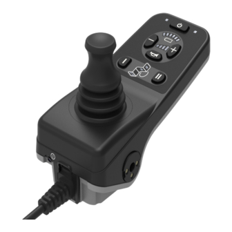
- Page 2 IDENTIFICATION KEY MAGNETIC CHARGER ADAPTER USB-c USB-c Charger Charger port port Magnetic Magnetic charger charger port port On/Off On/Off Mode jack Mode jack To charger To charger 6-key Joystick 10-key Joystick WARNING! WARNING! Your controller is equipped with an XLR and magnetic Maintain at least 6 in.
- Page 3 IDENTIFICATION KEY ATTENDANT CONTROL Joystick Battery Condition Meter On/Off Button Actuator Mode LED Mode On/Off and Mode Jacks...
-
Page 4: Safety Guidelines
We reserve the right to make changes as they become necessary. Any changes to A Quantum Rehab Provider or a qualified technician our products may cause slight variations between the must perform the initial setup of this product and must illustrations and explanations in this manual and the perform all of the instructions in this manual. -
Page 5: Table Of Contents
Lock/Unlock Procedure ........... 10 Offboard Charger Programming Socket ....11 Disposal and recycling - Contact USB Charging Port ..........11 your Quantum Rehab Provider for Interactive Assist............11 information on proper disposal and recycling of your Quantum product Attendant Control ..........11 and its packaging. -
Page 6: The Qlnes Controller
When the joystick is at rest, it is in the neutral create a dangerous situation. Only your Quantum (center) position and the chair is stationary. In order to drive Rehab Provider or a trained technician should program the chair, the joystick must be taken out of neutral. -
Page 7: Led Indications
BASIC OPERATION INSTRUCTIONS Bluetooth LED Hazard LED Light LED BDI LED Mode LED Indicator Left LED Indicator Right LED Seat LED LED Indications On/Off Button Light Button Hazard Button Minus Button Plus Button Horn Button Indicator Left Indicator Right Button Button Key I Key II... -
Page 8: Led Screen
Codes. 3. To decrease your profile, press the minus button. Keypad NOTE: Drive profiles are set by your Pride/Quantum The keypad is located directly in front of the joystick. It Rehab Provider. Contact your Pride/Quantum Rehab contains the components that you will use to control your Provider to change a drive profile or change speed power chair. -
Page 9: Actuator Adjustment
Pride/Quantum recommends charging the batteries as soon as possible when critical charge is reached. by your Pride/Quantum Rehab Provider. Contact your Pride/Quantum Rehab Provider to change the function of the jack. (For two actuators, a splitter harness will be WARNING! needed.) -
Page 10: Lock/Unlock Procedure
“lock out” unauthorized users. NOTE: The lock-out feature is not programmed at the factory. To have this feature added, contact your Quantum Rehab Provider. To lock the controller: 1. Press and hold mode keys until the system shuts off. -
Page 11: Offboard Charger Programming Socket
QLNES controller. If you use an off-board charger, the charger current should not exceed 8 amps. Contact your The Attendant Control is for use by an ambulatory attendant Pride/Quantum Rehab Provider for more information. and has the following controls: On/Off Button „... -
Page 12: Care And Maintenance
12 BASIC OPERATION INSTRUCTIONS Care and Maintenance Definition of Error Indicators Refer to your power chair owner’s manual for proper cleaning and disposal instructions. Display or error numbers LED 1 (Red) represents digit 1 „ Temperature LED 3 (Yellow) represents digit 2 „... -
Page 13: Error Codes
BASIC OPERATION INSTRUCTIONS Error Description Help text Code (programming device) (programming device) Error: Motor 1 not connected Motor 1 error detected. 1. Turn power off. 2. Inspect motor connections. 3. Turn power on. Defect: Motor 2 not connected Motor 2 error detected. 1. -
Page 14: Graphic User Interface Icons
14 BASIC OPERATION INSTRUCTIONS Power Use Case Trigger Precondition LEDs Regular startup Press ON/OFF Power is OFF - Outer right green LED shortly lit button -All LEDs shall turn ON for one second. Splash screen -Follows QLNES Power is ON BDI LED: regular startup -The left red and right green shall be turned OFF. - Page 15 BASIC OPERATION INSTRUCTIONS Seat Use Case Trigger Precondition LEDs Select actuator Deflect joystick to - Power is ON Next seat actuator LED per the right - Seat mode is active below direction shall be turned ON and the previous turned OFF: Multiple LED’s can be active depending on the seat configuration Select actuator...
- Page 16 16 BASIC OPERATION INSTRUCTIONS Drive Mode Use Case Trigger Precondition LEDs Increment drive Press plus button - Power is ON Increment drive mode. At 4 it shall jump to 1 speed - Drive Mode is active Drive Mode1 Drive Mode 2 Drive Mode 3 Drive Mode 4 Decrement Drive...
- Page 17 BASIC OPERATION INSTRUCTIONS Drive Mode Use Case Trigger Precondition LEDs Drive lockout Drive lockout - Power is ON Profile number in red detected by system. - Drive mode is active. - Drive lockout is active. Profile Drive Mode 1 Drive Mode 2 Drive Mode 3 Drive Mode 4 iLevel...
- Page 18 BASIC OPERATION INSTRUCTIONS Display of warnings Use Case Trigger Precondition LEDs Warning Error detected by -Power is ON The 2 yellow BDI LED flash for 4 seconds with a system frequency of 1 Hz. Stop Error Stop error detected - Power is ON LED 1 (Red) represents digit 1 by system LED 3 (Yellow) represents digit 2...
- Page 19 BASIC OPERATION INSTRUCTIONS Bluetooth Use Case Trigger Precondition LEDs BT not active - Power is ON Bluetooth LED shall be turned OFF - BT is not active Enable BT and Press ON/OFF -Power is ON Bluetooth LED shall blink in the frequency pairing mode button for 3s -BT is active...
- Page 20 BASIC OPERATION INSTRUCTIONS Attendant Control Use Case Trigger Precondition LEDs AC is set as input Press ON/OFF HCB is input device For a short moment the system changes in device button on AC splash screen, afterwards the LEDs shall remain as before.
-
Page 21: Emi/Rfi
BASIC OPERATION INSTRUCTIONS Electromagnetic Radio Frequency Interference (EMI/RFI) NOTE: This product has been tested for Electromagnetic and Radio Frequency Interference (EMI/RFI) and has met standard requirements. Please refer to the Consumer Safety Guide for more information regarding EMI/RFI. Although we do not recommend using a cell phone while operating a power chair, the system is capable of receiving and/or making calls through a cell phone device, accessing music files or contact lists, and... - Page 22 22 BASIC OPERATION INSTRUCTIONS...
- Page 24 Switzerland 401 York Avenue (Authorised CH Representative) Duryea, PA 18642 SODIMED SA www.quantumrehab.com Chemin Praz Devant 12 1032 Romanel-sur-Lausanne Canada Italy 5096 South Service Road Via del Progresso, ang. Via del Lavoro Beamsville, Ontario L3J 1V4 Loc. Prato della Corte www.quantumrehab.ca 00065 Fiano Romano (RM) www.quantumrehab-italia.it...
Need help?
Do you have a question about the Q-Logic NES and is the answer not in the manual?
Questions and answers