Table of Contents
Advertisement
Quick Links
Advertisement
Table of Contents

Related Manuals for Phasak Gate Pro PH 9270


Summary of Contents for Phasak Gate Pro PH 9270
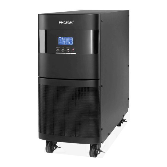
- Page 1 MANUAL Serie Gate Pro PH 9270 · 10000 VA www.phasak.com...
- Page 2 1. Precauciones 1.1. Transport Please transport the Phasak UPS in its original box to protect it from shocks and bumps. 1.2. Preparation · When the UPS goes from being in a warm environment to a cold one, condensation may form. The equip- ment must be completely dry before being installed.
- Page 3 1.4. Functioning • Do not disconnect the power cord of the UPS, otherwise the protection that the earth ground provides to the UPS and all its loads will be nullified. • The UPS has its own internal power supply (batteries). There may be voltages at the UPS output socket or output voltage terminals, even if the UPS is not connected to the mains.
-
Page 4: Safety And Emc Instructions
1. Safety and EMC Instructions Please read carefully the following user manual and the safety instructions before installing the unit or using the unit! 1-1. Transportation and Storage Please transport the UPS system only in the original package to protect against shock and impact. The UPS must be stored in the room where it is ventilated and dry. - Page 5 1-4. Operation Do not disconnect the earth conductor cable on the UPS or the building wiring terminals at any time, as this would cancel the protective earth of the UPS system and all connected loads. The UPS system features its own internal current source (batteries). The UPS output sockets or ou- tput terminal blocks may be electrically live even if the UPS system is not connected to the building wiring outlet.
-
Page 6: Unpacking And Inspection
2. Installation and Operation 2-1. Unpacking and Inspection Unpack the package and check the package contents. The shipping package contains: One UPS 2. One user manual 3. One monitoring software CD 4. One RS-232 cable (optional) 5. One USB cable 6. -
Page 7: Single Ups Installation
2-3. Single UPS Installation Installation and wiring must be performed in accordance with local electrical laws/regulations and executed by professional personnel. Follow these instructions: 1. Ensure appropriate mains wiring and breakers: • Verify that the building's wiring and breakers are sufficient for the UPS's rated capacity to avoid hazards like electric shock or fire. -
Page 8: Additional Notes
Notes: Ensure that the wires are connected tightly to the terminals. Two types of outputs are provided: Output Terminal/Outlets: For critical devices. Programmable Terminal: For non-critical devices. 2. During a power failure, you can extend the backup time for critical devices by setting a shorter backup time for non-critical devices. - Page 9 NOTE: The parallel system cannot use a single battery pack. Otherwise, this will cause perma- nent system failure. 6. Refer to the following wiring diagram for a parallel system: • Diagram 1: Power cable connection for the tower model • Diagram 2: Parallel communication port and share current cable connection Parallel communication port connection Share current cable connection...
-
Page 10: Software Installation
2-5. Software Installation To optimize computer system protection, install UPS monitoring software to fully configure UPS shutdown. Refer to the software installation manual for details. 3. Operations Button Functions: ON/Enter Button: • Turn on the UPS: Press and hold the button for more than 0.5 seconds to turn on the UPS. •... -
Page 11: Led Indicators And Lcd Panel
3.2 LED Indicators and LCD Panel There are 4 LEDs on the front panel to show the UPS working status: ● means the LED is lit. | ○ means the LED is off. LCD Panel:... - Page 12 Display Function Backup time information Indicates battery discharge time in numbers. H: hours, M: minutes, S: seconds Fault information Indicates that the warning and fault occurs. Indicates the fault codes, and the codes are listed in details in section 3-9. Mute operation Indicates that the UPS alarm is disabled.
-
Page 13: Audible Alarm
3.3 Audible Alarm... -
Page 14: Single Ups Operation
3.4 Single UPS Operation Turn on the UPS with utility power supply (AC mode): • After correctly connecting the power supply, set the breaker of the battery pack to the "ON" position (only for long-run models). Then, set the input breaker to the "ON"... - Page 15 Charge the batteries: • After connecting the UPS to utility power, the batteries will charge automatica- lly except during Battery mode or a battery self-test. • Charge the batteries for at least 10 hours before first use. Battery mode operation: •...
-
Page 16: Abbreviation Meaning In Lcd Display
Add a New Unit to the Parallel System: • Shut down the entire system before adding a new unit. • Ensure the new UPS is a parallel-compatible model and follow the wiring instruc- tions in Section 2-3. Remove a Unit from the Parallel System: •... -
Page 17: Lcd Setting
3.7 LCD Setting There are three parameters for setting up the UPS. Refer to the diagram below: • Parameter 1: Program alternatives (15 programs available). • Parameter 2: Setting options or values for each program. • Parameter 3: Corresponding value to Parameter 2. Parameter 1... - Page 18 01: Output voltage Setting Parameter 3: Output voltage You may choose the following output voltage in parameter 3: 208: Presents output voltage is 208Vac 220: Presents output voltage is 220Vac 230: Presents output voltage is 230Vac 240: Presents output voltage is 240Vac 02: Output frequency Setting 60 Hz, CVCF mode...
- Page 19 06: Voltage range for ECO mode Setting Parameter 2: Low voltage point in ECO mode. The setting range is from 5% to 10% of the nominal voltage. Parameter 3: High voltage point in ECO mode. The setting range is from 5% to 10% of the nominal voltage. 07: Frequency range for ECO mode Setting Parameter 2: Set low frequency point for ECO mode.
- Page 20 11: Shutdown point for programmable output Note:This function is not supported by the Rack model. Setting Parameter 2: 001. Set shutdown time for programmable output. Parameter 3: Shutdown time in minutes. Setting range is from 0 to 300. When shutdown time arrives, the programmable output terminal will be cut off.
-
Page 21: Operating Mode/Status Description
3.8 Operating Mode/Status Description If parallel UPS systems are successfully set up, it will show one more screen with “PAR” in parameter 2 and be assigned number in parameter 3 as below parallel screen diagram. The master UPS will be default assigned as “001” and slave UPSs will be assigned as either “002”... - Page 22 Bypass mode Description When input voltage is within acceptable range and bypass is enabled, turn off the UPS and it will enter Bypass mode. Alarm beeps every two minutes. LCD display Battery Test Description When UPS is in AC mode or CVCF mode, press “Test” key for more than 0.5s.
-
Page 23: Warning Indicator
3.10 Warning Indicator Warning I con (flashing) Alarm Battery low Beeping every second Overload Beeping twice every second Battery unconnected Beeping every second Over charge Beeping every second EPO enable Beeping every second Fan failure/Over temperature Beeping every second Charger failure Beeping every second I/P fuse broken Beeping every second...
Need help?
Do you have a question about the Gate Pro PH 9270 and is the answer not in the manual?
Questions and answers