Noctua NH-L12S Manual
- Installation manual (7 pages) ,
- Installation manual (18 pages)
Advertisement
Introduction
This manual will guide you through the installation process of the SecuFirm2™ mounting system step by step.
Prior to installing the cooler, please consult the compatibility centre on our website (ncc.noctua.at) and verify that the cooler is fully compatible with your motherboard.
Please also make sure that your PC case offers sufficient clearance for the cooler and that there are no compatibility issues with any other components (e.g. tall RAM modules).
Double check that the heatsink and fan clips do not make contact with the VGA card, other PCIe cards, motherboard heatsinks or any other components.
Noctua cannot be held responsible for any damage or losses caused by compatibility issues.
Should you encounter any difficulties, please check the FAQs on our website (www.noctua.at/faqs) and don't hesitate to contact our support team at support@noctua.at.
LGA1700, LGA1200 & LGA115x
Required mounting parts

Removing the motherboard
If you would like to use the cooler on an assembled system and your case does not have a cut-out at the rear side of the motherboard tray, you must first remove the motherboard from the case in order to be able to install the supplied backplate.
Setting up the backplate
First, identify the side of the backplate that should face the motherboard (marked with caution signs). Then choose the appropriate hole spacing for your socket and insert the four bolts into the backplate from the opposite side (marked with model name, SecuFirm2™ branding and numbers for hole spacing) at the appropriate position.

Use hole position 1 for LGA1200/115x (LGA1150, LGA1151, LGA1155, LGA1156) and hole position 2 for LGA1700 (LGA17xx family):
Position 1: LGA1200/115x

Position 2: LGA1700

Fix the bolts using the NM-ICS1 clip-on spacers. Note that 2 extra clip-on spacers are supplied in case any are lost or damaged when removing the bolts at a later point.

Attaching the backplate
Place the backplate on the rear side of the motherboard so that the bolts protrude through the mounting holes.


The supplied backplate will install over the motherboard's stock backplate, so the motherboard's stock backplate must not be taken off.
Installing the mounting bars
Please first choose the correct set of plastic spacers and the correct set of holes on the mounting bars according to whether you are using an LGA1200/LGA115x (LGA1150, LGA1151, LGA1155, LGA1156) or an LGA1700 (LGA17xx family) socket motherboard.
Use the black NM-IPS1 plastic spacers for LGA1200/ LGA115x (LGA1150, LGA1151, LGA1155, LGA1156) and the blue NM-IPS3 spacers for LGA1700 (LGA17xx family).

Use hole position 1 for LGA1200/115x (LGA1150, LGA1151, LGA1155, LGA1156) and hole position 2 for LGA1700 (LGA17xx family):
Position 1: LGA1200/115x

Position 2: LGA1700

Make sure to use the correct hole position on both ends of the NM-IMB3 mounting bars so that they will not be misaligned.

Put the plastic spacers onto the bolts of the backplate, then add the mounting bars.

Choose the alignment of the mounting bars according to the desired final orientation of the cooler.
Orientation A

Orientation B

Make sure that the curved sides of the mounting bars are pointing outwards.

Fix the mounting bars using the four NM-ITS1 thumb screws.

Gently tighten the screws until they stop, but do not use excessive force (max. torque 0.6 Nm).
Applying the thermal paste
If there are residual traces of thermal paste or thermal pads on your CPU, please clean them off first. Then apply the supplied NT-H1 thermal paste onto the CPU as shown in the following images.
For LGA1700 (LGA17xx family), apply 5 small dots; 4 dots with ~2mm diameter near the corners plus 1 dot with 3-4mm diameter in the centre:

For LGA1200/115x (LGA1150, LGA1151, LGA1155, LGA1156) apply a single 4-5mm dot in the centre:

Applying too much thermal paste will lower heat conductivity and cooling performance!
Fan configuration
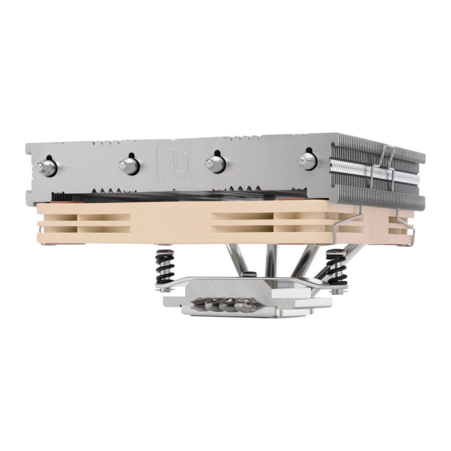
The NH-L12S ships with the fan installed underneath the fins (low profile mode).
Alternatively, you can take off the fan and install it on top of the fins to make more room for tall RAM or other components (high clearance mode).
 Note that the NH-L12S will provide best performance to noise efficiency in high clearance mode.
High clearance mode

Low profile mode

Fastening the heatsink to the CPU
Please first take off the protection cover at the bottom side of the heatsink.
Then put the heatsink onto the CPU and screw it to the screw threads of the mounting bars.
Perform 2-3 turns on each screw, then repeat until both are fully tightened.

Note that you can reach through the blades of the fan using the supplied screw driver. There is thus no need to take off the fan for installation.
Gently tighten the screws until they stop, but do not use excessive force (max. torque 0.6 Nm).
Fan setup
Connect the fan to the motherboard's CPU fan header.
Depending on your CPU and the temperature inside the case, you may interconnect the supplied NA-RC7 Low-Noise Adapter (L.N.A.) in order to further reduce the fan's operating noise.
When using the L.N.A., check the temperature of your CPU using appropriate software (e.g. the respective applications of your motherboard manufacturer), in order to evade automatic throttling of the CPU due to the increased temperature.
If the cooling performance is insufficient, please increase case ventilation or remove the L.N.A.
Transporting your system
Due to the low weight of the cooler, it is not necessary to take it off for transport.
LGA20xx
Required mounting parts

Installing the mounting bars

Then put the NM-IMB3 mounting bars onto the bolts.

Choose the alignment of the mounting bars according to the desired final orientation of the cooler.
Orientation A

Orientation B

Make sure that the curved sides of the mounting bars are pointing outwards.

Fix the mounting bars using the four NM-ITS1 thumb screws.

Gently tighten the screws until they stop, but do not use excessive force (max. torque 0.6 Nm).
Applying the thermal paste
If there are residual traces of thermal paste or thermal pads on your CPU, please clean them off first.
Then press a small drop with 4-5mm diameter of NT-H1 thermal paste onto the centre of the heatspreader.

Applying too much thermal paste will lower heat conductivity and cooling performance!
Fan configuration
Please refer to step 6 of the LGA1700, LGA1200 & LGA115x installation manual.
Fastening the heatsink to the CPU
Please refer to step 7 of the LGA1700, LGA1200 & LGA115x installation manual.
Fan setup
Please refer to step 8 of the LGA1700, LGA1200 & LGA115x installation manual.
Transporting your system
Due to the low weight of the cooler, it is not necessary to take it off for transport.
AMD (AM4 & AM5)
Required mounting parts
 - Required mounting parts")
Removing the stock retention module − putting the backplate in place
If your motherboard comes with a pre-installed CPU cooler retention module, please first remove it by unscrewing it from the backplate. The SecuFirm2™ mounting system will install directly to the stock backplate, so please keep it in place.

If your motherboard does not come with a pre-installed CPU cooler retention module, the AMD stock backplate should be included with the motherboard accessories. Please put the backplate on the rear side of the motherboard so that the screw threads of the backplate stick through the mounting holes of the motherboard as shown below. If your motherboard does not include a stock backplate, please contact our Noctua service team at support@noctua.at.

Attaching the mounting bars
Choose either the short NM-AMB6 or the long NM-AMB7 mounting bars according to the desired final orientation of the cooler.
Orientation NM-AMB6

Orientation NM-AMB7

First put the plastic spacers onto the screw threads of the backplate, then fix the mounting bars using the four NM-ALS1 long screws.

For the short NM-AMB6 mounting bars, make sure that the curved sides are pointing inwards.

For the long NM-AMB7 mounting bars, make sure that the curved sides are pointing outwards.

Gently tighten the screws until they stop, but do not use excessive force (max. torque 0.6 Nm).
Applying the thermal paste
If there are residual traces of thermal paste or thermal pads on your CPU, please clean them off first.
Apply 5 small dots; 4 small dots with ~2mm diameter near the corners plus 1 dot with 3-4mm diameter in the centre:
 - Applying the thermal paste")
Applying too much thermal paste will lower heat conductivity and cooling performance!
Fan configuration
The NH-L12S ships with the fan installed underneath the fins (low-profile mode).
Alternatively, you can take off the fan and install it on top of the fins to make more room for tall RAM or other components (high-clearance mode).
Note that the NH-L12S will provide best performance to noise efficiency in high-clearance mode.
High-clearance mode
 - Fan configuration - High")
Low-profile mode
 - Fan configuration - Low")
Fastening the heatsink to the CPU
Please first take off the protection cover at the bottom side of the heatsink.
Then put the heatsink onto the CPU and screw it to the screw threads of the mounting bars. Perform 2-3 turns on each screw, then repeat until both are fully tightened. Note that you can reach through the blades of the fan using the supplied screw driver. There is thus no need to take off the fan for installation.

Gently tighten the screws until they stop, but do not use excessive force (max. torque 0.6 Nm).
Fan setup
Connect the fan to the motherboard's CPU fan header.
Depending on your CPU and the temperature inside the case, you may interconnect the supplied NA-RC7 Low-Noise Adaptor (L.N.A.) in order to further reduce the fan's operating noise.
When using the L.N.A., check the temperature of your CPU using appropriate software (e.g. the respective applications of your motherboard manufacturer), in order to evade automatic throttling of the CPU due to the increased temperature.
If the cooling performance is insufficient, please increase case ventilation or remove the L.N.A.
Transporting your system
Due to the low weight of the cooler, it is not necessary to take it off for transport.
Warranty, support and FAQs
Even with high-grade products and strict quality control, the possibility of defects cannot be eliminated entirely. Therefore, we aim at providing the highest possible level of reliability and convenience by offering a warranty period of 6 years and direct, fast and straightforward RMA service.
Should you encounter any problems with your NH-L12S, please don't hesitate to contact our support team (support@noctua.at).
Please also consult the FAQ section on our website: www.noctua.at/faqs
Documents / Resources
References
Download manual
Here you can download full pdf version of manual, it may contain additional safety instructions, warranty information, FCC rules, etc.
Advertisement


Need help?
Do you have a question about the NH-L12S and is the answer not in the manual?
Questions and answers