Advertisement
Features
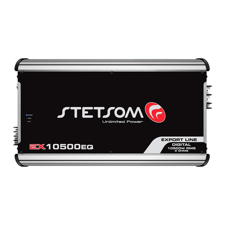
The EX10500EQ offer 1 channel with advanced individual equalization features for Bass, Mid Bass and Mid High, plus the traditional Level, High Pass and Low Pass features. Its Full Range frequency response from 10Hz to 15KHz allows the installation of Subwoofers, Woofers, Drivers and Twitters.
Before Installing
Read this manual carefully before installing the amplifier. You must follow the instructions for the product's installation and connections to guarantee optimal performance. If you have any questions, get in touch with us. Before using the amplifier, always follow these guidelines:
- Make sure the appliance is switched off before adding or removing any connections. This prevents possible damage to the equipment connected to the amplifier;
- Keep all cables as far away as possible from the ignition cables, electronic injection modules and starter switch since they may cause noise interference;
- Always use good quality cables and connectors. This guarantees the sound's quality and fidelity;
- To avoid damaging the cables, make sure that they do not touch sharp metal edges.

Use a 400A fuse 30 centimeters from the battery as a safety precaution.
General Description

- 11. 12. 17. VENTS: Allows for the removal of warm air from the amplifier.
- RCA OUTPUT: This output can be used optionally to play another amplifier, facilitating installation in multi-amplified systems.
- RCA INPUT: This input should receive the signal through an RCA cable connected to the output of the CD/MP3 player.
LEVEL (LEVEL CONTROL): Controls the input signal level, allowing for proper control of any CD/MP3 player currently on the market. It can be regulated as the following:- on the CD/MP3 player, play any musical signal up to 80% volume.
(Ex: If the maximum volume on the player is 45 [100%], adjust to 36 [80%]). - on the amplifier, beginning at the lowest LEVEL, gradually increase until the clipping LED begins to flash.
- slowly decrease the LEVEL until the LED goes off. (see entry 9 "OVER CLIP")
- on the CD/MP3 player, play any musical signal up to 80% volume.
- HIGH PASS FILTER: Allows cut off of low frequency (subsonic) signals. This filter is very useful for woofer-type speakers. In these cases, the woofers are not capable of reproducing subsonic frequencies, and these subsonic frequencies may even cause damage depending on the volume and the music played. It is regulated from 10Hz to 700Hz).
- LOW PASS FILTER: This control varies the cut off frequency from 50Hz to 15KHz. This filter allows to pass only sounds beneath the cut frequency.
- BASS: This control provides gain/attenuation of ±10dB in low frequency. Central frequency is 45Hz.
- MID-BASS: This control provides gain/attenuation of ± 10dB in mid-low frequency. Central frequency is 270Hz.
- MID-HIGH: This control provides gain/attenuation of ±10dB in mid-high frequency. Central frequency is 2KHz.
- OVER CLIP (ON/OFF): With this key turned on, the clipping LED will light up at 15% more final capacity.
- SPEAKER OUTPUT: This output is MONO. Be careful of maintaining the correct polarity of the connections between the speakers and check the minimum impedance of this output. Use cables with a minimum gauge of 7 AWG.
- COOLER: This fan will work when the device is triggered. They provide the device cooling.
- POSITIVE POWER SUPPLY
![]() : Connect the terminal
: Connect the terminal ![]() (+BAT) to the positive terminal of the battery (+12V) with a minimum gauge of 00 AWG. It is extremely important that a protective fuse or circuit breaker be used on this cable at a distance of 30 cm from the battery. The fuse or circuit breaker should be, at minimum, equal to the max current consumption value caused by playing musical signals (see technical specifications table).
(+BAT) to the positive terminal of the battery (+12V) with a minimum gauge of 00 AWG. It is extremely important that a protective fuse or circuit breaker be used on this cable at a distance of 30 cm from the battery. The fuse or circuit breaker should be, at minimum, equal to the max current consumption value caused by playing musical signals (see technical specifications table). - REM (REMOTE CONTROL): Connect the REM terminal to the electric antenna output of the CD/MP3 player. This will cause the amplifier to turn on automatically when you turn on your CD/MP3 player. A cable with a gauge of 20 AWG is adequate.
- GROUND CONNECTION
![]() : Use a cable with a gauge of at least 00 AWG. Connect the cable to the chassis of the vehicle. (Note: always connect the GND wire
: Use a cable with a gauge of at least 00 AWG. Connect the cable to the chassis of the vehicle. (Note: always connect the GND wire ![]() of the CD player — or other equipment — to the same ground point.)
of the CD player — or other equipment — to the same ground point.)
 : Connect the terminal
  : Use a cable with a gauge of at least 00 AWG. Connect the cable to the chassis of the
 - POWER LED (BLUE): This indicator LED will light up when it is activated by the remote control signal from the CD/MP3 player.
- PROT LED (RED): This LED will light up for the following reasons (see the diagnostic table on the back cover):
- Short circuit in the speakers
- Excessive temperature
- Low battery voltage
- High battery voltage
- CLIP LED (RED): This LED will light up when the signal begins to suffer distortion.
Installing the Input Cables
 ATTENTION: The use of a the fuse or breaker is required, since this amplifier has no internal fuses.
In order to install the power supply, use cables with a gauge of 00 AWG. The positive cable should come straight from the battery and have a fuse or protective breaker 30cm from the battery. The negative cable should have the same gauge as the positive cable and be screwed to the chassis of the vehicle, being careful to avoid paint and rust. These may interfere with the flow of the electrical current and cause loss of power and interference in the sound.

RECOMMENDED USE OF AUXILIARY BATTERY.
Installation of the Speaker Outputs
The speaker cables should be polarized (marked) so that you can easily identify which is positive and which is negative. Minimum gauge is 7 AWG. Keep the cables well insulated and avoid metal parts as these may damage the insulation.

Troubleshooting
NO POWER
- The power cables are not connected correctly (terminals +BAT, GND and REM). Verify that all the connections have electrical and mechanical contact.
- The fuse/circuit breakers are defective or blown. Replace them, making sure that the replacements are the correct ones!
NO SOUND
- The speaker cables or RCA plugs are not connected correctly.
- Verify that the LEVEL control is at the lowest setting. Check the amplifier filter controls.
NO SOUND. RED ALERT PROT BLINKING
- See diagnostic guide
- The speakers or cables are defective, so check speakers, cables and connections.
POOR SOUND QUALITY (DISTORTIONS)
- The speakers are overloaded. Decrease and readjust the volume level (see entry, "LEVEL (LEVEL CONTROL)")
WEAK BASS:
- Speaker cables (+) and (-) are switched or the speaker is out of phase (see entry "INSTALLATION OF THE SPEAKER OUTPUTS"). Also check BASS control adjustment.
ENGINE, HORN, TURN SIGNAL, INTERFERENCE
- Use suppressing/insulated cables on the spark plugs.
- Use capacitors on the alternator, horn and ignition.
- Run the shielded input cable away from any other cables, as they are particularly prone to interference.
- Install a separate power source (+12V) for the sound system. Use a fuse/circuit breaker 30 centimeters from the battery as the best precaution.
- Ground the amplifier properly. Remove paint from the chassis at the selected point, and connect the wire using a grounded terminal. In order to prevent rust, insulate it with paint.
Do not loop the ground. Avoid using multiple grounds. If possible, use a star connection, in which all the grounds run from a single point.
Diagnost Guide
In the eventuality of any problems, the amplifier will power down and the RED LED (PROT) light will begin to blink. Depending on the problem, the RED LED (PROT) light will flash a certain number of ti mes. The following table summarizes the diagnostics:
| Number of Flashes | Problem | Solution |
 | Output short circuit or overload. | Check to make sure the speaker cables are properly isolated. Verify minimum impedance. |
 | Overheati ng. | Make sure the equipment is installed in a well ventilated location. |
 | Low battery. | When used for long periods, the batt ery will run down. Recharge the batt ery. |
 | Batt ery overload or voltage greater than allowed. | Have the batt ery and/or alternator checked by a professional. |
NOTE: In the event that the RED LED (PROT) light is flashing continuously, unplug the speakers and turn the equipment back on. If the problem persists, contact STETSOM tech support.
Technical Specifications
| EX10500EQ 1 OHM | EX10500EQ 2 OHMS | |
| Channels: | 1 | 1 |
| Power @ 14.4V - 1 Ohm (RMS): | 10500W | — |
| Power @ 14.4V - 2 Ohms (RMS): | 7000W | 11000W |
| Power @ 14.4V - 4 Ohms (RMS): | — | 7000W |
| Min. Output Impedance: | 1 OHM | 2 Ohms |
| Input Impedance: | 25K OHMS | 26K Ohms |
| Input Sensitivity: | 0.2V | 0.2V |
| T.H.D: | ≤ 10% THD | ≤ 10% THD |
| Signal to Noise Ratio: | >90dB | >90dB |
| Freq. Resp. (-3dB) @ 1 Ohm: | 10Hz ~ 15KHz | 10Hz ~ 15KHz |
| Crossover Low Pass: | 50Hz ~ 15KHz | 50Hz ~ 15KHz |
| Crossover High Pass: | 10Hz ~ 700Hz | 10Hz ~ 700Hz |
| EQ - BASS @ 45Hz: | ±10dB | ±10dB |
| EQ - MID BASS @ 270 Hz: | ±10dB | ±10dB |
| EQ - MID HIGH @ 2KHz: | ±10dB | ±10dB |
| Over Clip (Power): | 15% | 15% |
| Power Supply: | 9.5 ~ 15Vdc | 9.5 ~ 15Vdc |
| Consumpti on Music: | 6.7 ~ 495A | 6.7 ~ 495A |
| Consumpti on BASS: | 6.7 ~ 990A | 6.7 ~ 990A |
| Dimensions (H x W x L): | 77 x 294 x 510 mm | 77 x 294 x 510 mm |
| Weight: | 7.5 Kg | 7.5 Kg |
 The measured data are based on equipment from the STETSOM laboratory. Frequency reference of 1Khz with THD+N to ≤10% in impedances referring to the indicated in each measurement. The electronic components and the manufacturing process can present manufacturing variati ons, thus leading to a variati on in the measurements made.
Documents / ResourcesDownload manual
Here you can download full pdf version of manual, it may contain additional safety instructions, warranty information, FCC rules, etc.
Advertisement


Need help?
Do you have a question about the EX10500EQ and is the answer not in the manual?
Questions and answers