Hoymiles HMS-1600-4T, HMS-1800-4T, HMS-2000-4T Manual
- User manual (43 pages) ,
- Quick installation manual (2 pages) ,
- Quick installation manual (2 pages)
Advertisement
- 1 Using This Manufial
- 2 About This Manual Validity
- 3 Safety Instructions
- 4 Product Information
- 5 Installation Steps
- 6 Commissioning
- 7 Troubleshooting List
- 8 LED Indicator Status
- 9 On-Site Inspection and Maintenance Instructions
- 10 Decommission
- 11 Technical Data
- 12 Installation Map
- 13 WIRING DIAGRAM
- 14 Grid Profile Parameters
- 15 Contact Us
- 16 Documents / Resources
Using This Manufial
Symbols
| • | List |
| 1., 2, ... | Installation steps in a defined order |
| A, B, C... | Installation steps in a defined order (second level) |
Abbreviations
| Abbreviation | Meaning | Abbreviation | Meaning |
| AC | Alternating Current | PE | Protective Earthing |
| AP | Access Point | PPE | Personal Protective Equipment |
| DC | Direct Current | PV | Photovoltaic |
| MPPT | Maximum Power Point Tracking | RCD | Residual Current Device |
| O&M | Operations and Maintenance | SN | Serial Number |
About This Manual Validity
This manual is valid for:
| Model | Output Power (W) |
| HMS-1600-4T | 1600 |
| HMS-1800-4T | 1800 |
| HMS-2000-4T | 2000 |
NOTE
Model identifier:

- Series Name
- Output Power Level
- Number of Inputs
Safety Instructions
Safety Symbols
Safety symbols are used in this manual as follows:
| Symbol | Description |
 | This symbol indicates warns of hazards that could cause death or serious physical harm. |
 | This symbol signifies the importance of strictly following directions to avoid safety hazards, including damage to equipment and personal injury. |
 | This symbol indicates potential risks that, if not avoided, may lead to device malfunctions or financial losses. |
| NOTICE | This symbol indicates potential risks that, if not avoided, may lead to minor injury or damage to the equipment. |
 NOTE NOTE | This symbol indicates an important step or tip that leads to the best results but is not safety or damage-related. |
Additional Symbols
The product label contains the following symbols with their meanings described below:
| Icon | Explanation |
  | Caution Risk of electrical shock. |
 | High Voltage Microinverters may contain high voltages, causing a risk of death. |
 | Hot Surface The microinverter may become hot during operation. Do not contact with metal surfaces. |
Safety Instructions
The HMS-2000-4T microinverter has been designed and tested in compliance with international safety standards, and thus requires careful installation and operation. Installers must carefully read and strictly follow the safety instructions in this section. Failure to do so may result in:
- Injury or death to the installer or operator
- Damage to the microinverter
General
- All installation, start-up, troubleshooting, maintenance, and all other operations must be performed by a licensed electrician and follow local wiring codes.
- Always use personal protective equipment (PPE), like gloves and goggles, during installation.
- The microinverter should only be used when all technical parameters are observed and applied correctly. (You can refer to "Technical Data" for more details.)
Installation & Operation
- Report any non-standard installation conditions to the manufacturer.
- Do not install the equipment in flammable, explosive, corrosive, extreme heat/cold, or humid environments.
- Each microinverter input should only be connected to a single PV module. Do not connect batteries or other power supply sources. The unsupported devices have different output characteristics that differ from PV modules, potentially leading to improper functioning of the microinverters and posing safety hazards.
- Do not use the equipment in environments where safety devices are not working properly.
- Do not use the equipment if any unusual operations are detected.
- Check and ensure that all AC and DC wiring is properly installed and free from any snags, shorts, or damage. Additionally, ensure that all AC distribution boxes are securely sealed.
- Hoymiles shall not be liable for any damages caused by incorrect or improper operations.
Maintenance & Repair
- Ensure that the DC connectors are in perfect condition and that none of the DC conductors or DC connectors are exposed.
- Do not attempt to repair the product. All repairs must be done by licensed contractors or authorized Hoymiles service representatives using approved spare parts installed according to their intended use.
- Prior to any maintenance and repair operation, disconnect the power supply. Do not disconnect the AC and DC connectors under load.
- Maintain extreme caution when the microinverter is disconnected from the public grid. Hazardous voltages may still be present in some components
General
- Disconnect the microinverter from the electrical power supply before making or modifying any device connections.
- Restrict product access by unauthorized individuals.
Installation & Operation
- Make sure to obtain all necessary approvals from local power operators before connecting the microinverter to the power grid.
- To protect from rain, UV, and adverse weather conditions, install the microinverter beneath the PV module. Avoid exposing the AC and DC connectors to rain or moisture prior to connection.
- Use the Hoymiles Compatibility Calculator to verify the electrical compatibility of PV modules. To maintain the Hoymiles warranty, only use Hoymiles microinverters with the compatible PV modules shown on the Hoymiles Compatibility Calculator.
- Make sure that the PV module's maximum open circuit voltage falls within the maximum DC input voltage for the microinverter. (You can refer to "Technical Data" for more details.)
![]()
Improper use, incorrect installation, or unauthorized removal of necessary protections may result in damage to the equipment or serious safety and shock hazards.- Microinverter surfaces can reach high temperatures during operation and for a short time after switching off the AC circuit breaker. Avoid direct contact with these surfaces.

Maintenance & Repair
- Avoid immersing the cable connectors or cables for a long period.
- Prevent any contaminants or deposits from entering the connector.
- Equipment repairs should only be performed by the Hoymiles Service Team, a repair team authorized by Hoymiles, or by authorized personnel familiar with all warnings and operating procedures contained in this manual.
- Ensure that the installation surface and equipment are within safe temperature and voltage ranges prior to handling any part of the microinverter.
Installation & Operation
- Before installation, inspect for transportation damages compromising insulation integrity and safety clearances.
- Do not remove or cover any warning labels or nameplates on the microinverter.
- Lift the microinverter carefully. Take the weight of the microinverter into account.
- Follow the wiring safety instructions to ensure proper polarity and secure connections.
- Inspect the microinverter system for functionality and performance post-installation. Double-check the electrical connections, communication links, and monitoring features.
Maintenance & Repair
- The microinverter packaging has been intentionally designed to be reusable. Retain the packaging for future use.
- Do not clean the equipment with filamentary or corrosive material-based rags to prevent corrosion and electrostatic charges
NOTICE
- The microinverter is an isolated device that manages power conversion and safety at the module level, so it does not need functional grounding for the PV array.
- The microinverter uses High Frequency transformer. For some countries that an external RCD (Residual Current Device) is required, Hoymiles recommends the use of a type-B 30 mA RCD
Product Information
Overview
Functions
Microinverters are module-level power electronics that convert direct current (DC) into alternating current (AC). The HMS-2000-4T microinverter is well-suited for residential and small commercial installations. It can attach up to four PV modules, enabling grater efficiency and flexibility in energy production.
Features
- Maximum output power up to 1600/1800/2000 W
- Independent Maximum Power Point Tracking (MPPT) technologies, keeping your solar power always on
- Hassle-free assembly with a user-friendly plug-and-play design
- With Reactive Power Control, compliant with EN 50549-1:2019, VDE-AR-N 4105:2018, VFR2019, etc.
- Maximum efficiency 96.7%
- Adjustable power factor, supporting 0.8 leading and 0.8 lagging
- Enhanced safety with rapid shutdown compliance and isolated transformer
- Durable and reliable IP67 (NEMA 6) enclosure, 6000 V surge protection
Applications
See Figure 1-1.
The HMS-2000W-4T microinverter can work in two types of systems: single-microinverter system and multi-microinverter system.
In a single-microinverter system, the whole system includes one microinverter and four PV modules. This setup is great for places like balconies or outdoor areas with lots of sunlight, like gardens, front lawns, and terraces.
In a multi-microinverter system, you'll have multiple microinverters, each paired with four PV modules. These setups are usually found on rooftops.

NOTE
For each type of setup, you'll need different accessories.
- Single-Microinverter system:
You can order an HMS Field Connector and get an AC cable ready for connection.
 | HMS Field Connector It provides a quick and simple electrical connection between the microinverter and the grid by serving as a joining component. To use it, you should prepare an AC cable to connect to it to form the AC end cable. |
- Multi-Microinverter system:
You'll need to order the HMS Cable System and prepare an AC cable and a distribution box to connect the microinverters to the grid. The HMS Cable System includes these components:
 | HMS Connection Cable Make a customized AC Trunk by using the HMS Trunk Connectors and HMS Extension Connectors. |  | HMS Trunk Connector Used to connect the microinverter's AC output to the AC Trunk, as well as to join together multiple HMS Connection Cables to create the AC Trunk. |
 | HMS Cable Terminal Connector Used to form the AC cable into an AC End Cable, which completes the connection between the end of the AC Trunk and the distribution box. |  | HMS Extension Connector Used to extend your cable runs when the distance between two microinverters exceeds the standard length of an HMS Connection Cable. |
 | HMS Sealing Cap Used to cover the unused connection port on the HMS Trunk Connector, which is typically located at the beginning of the AC Trunk. |  | HMS Disconnect Tool A versatile tool that can be used to take apart connectors, tighten nuts, and loosen nuts. |
How the System Works
In a typical microinverter system, a few parts team up to turn sunlight into power you can use. See Figure 1-2.

- PV modules
The PV modules capture sunlight and change it into DC electricity. - Microinverters
Microinverters are small inverters installed directly on PV modules or nearby. They convert DC electricity from the PV modules into AC electricity, which can power homes or be fed back into the grid.
Microinverters use a sophisticated maximum power point tracking (MPPT) algorithm to optimize the performance of each PV module. This ensures that even if one PV module under performs, it will not drag down the overall performance of the other PV modules in the row. - DTU
The Data Transfer Unit (DTU) is Hoymiles communication gateway. It bridges the communication between microinverters and S-miles Cloud Platform. It collect and delivers microinverter production data and energy consumption data to the S-Miles Cloud platform for monitoring and remote operations and maintenance (O&M). - S-Miles Cloud
The S-Miles Cloud is a comprehensive monitoring and analysis platform. It watches over the microinverter system from afar, providing real-time insights into the whole system's performance and enabling you to keep track of your microinverter system's status. The S-Miles Cloud also enables module-level monitoring, and remote management.
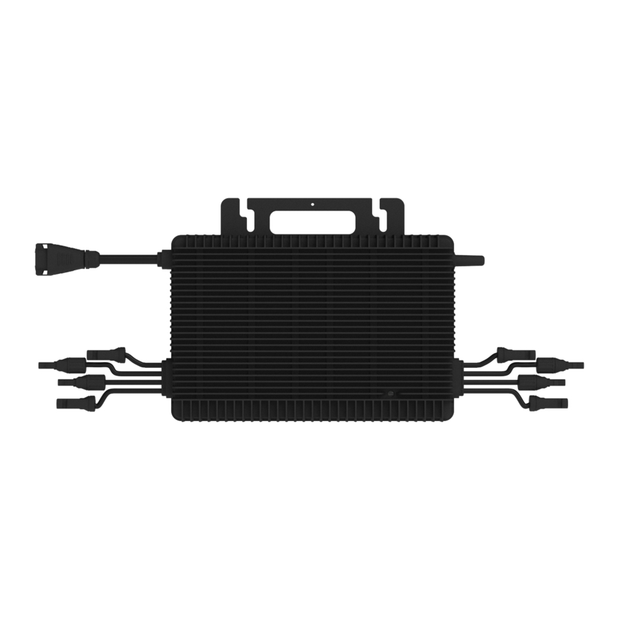
Appearance and Dimensions
NOTE
The appearance and dimensions shown here are for reference only. The actual product you receive may differ.

Appearance

Dimensions (mm)
Installation Steps
Preparation
Unpacking the Box
The microinverter has been thoroughly tested and was subject to a strict inspection before delivery. However, damage may still occur during shipping.
Conduct a detailed inspection after unpacking the microinverter:
- Check for any external damage
- Check and confirm that all items have been included
![]()

NOTICE
Immediately contact your supplier or distributor upon noticing any damaged or missing parts.
Checking the Parts
- Single-Microinverter System
![]()
- Multi-Microinverter System
![]()


NOTE
Hoymiles doesn't offer the AC cable and mounting bracket for sale. You need to buy them separately. When purchasing, ensure compliance with local regulations and consider the following guidelines:
- AC cable: ensure it meets the necessary requirements.
| Type | Wire Type | Size | Cross-section Diameter | Maximum Voltage |
| Single-Microinverter System | Outdoor Use, Copper Wire | 1.5 /1.0 mm² |  8 - 9.5 mm 8 - 9.5 mm | - |
| Multi-Microinverter System | Outdoor Use, Copper Wire | 2.5/4/6 mm² | ≤ 16.5 mm | 600 V |
- Mounting Bracket: Ensure the bracket has the load-bearing capacity and wind resistance to support the microinverter effectively.
Checking the Tools
Installation tools include but are not limited to the following recommended ones. If necessary, use other auxiliary tools on site.
- Single-Microinverter System
![]()
- Multi-Microinverter System
![]()


Downloading the Application
Download the S-Miles Installer application. To download,
- Scan the QR code located below, or,

- Search for "S-Miles Installer" on the App Store or Google Play Store
![]()


Planning the Units
You should specify the number of microinverters per AC output line based on the AC cables' capacity.
| Maximum Microinverter Number per Line | |||
| Model | HMS-1600-4T | HMS-1800-4T | HMS-2000-4T |
| 2.5 mm² | 3@220V | 2@220V | 2@220V |
| 3@230V | 3@230V | 2@230V | |
| 3@240V | 3@240V | 2@240V | |
| 4 mm² | 4@220V | 3@220V | 3@220V |
| 4@230V | 4@230V | 3@230V | |
| 4@240V | 4@240V | 3@240V | |
| 6 mm² | 5@220V | 4@220V | 4@220V |
| 5@230V | 5@230V | 4@230V | |
| 6@240V | 5@240V | 4@240V | |
NOTICE
- Limits are determined based on AC cable ampacity, which can vary. Check local codes to determine the exact restrictions.
- Multiple 1-in-1, 2-in-1, and 4-in-1 microinverters can be connected to the same AC output line, as long as the total current doesn't exceed the local regulations' ampacity limits.
Determining the Installation Position
Consider the following to ensure the optimal location for the microinverter:
- The microinverter meets the IP67 rating for environmental protection and can be installed indoors or outdoors.
![]()
- Shield the microinverter and DC connections from sunlight, rain, snow, UV, and other elements by installing them beneath the PV module.
![]()
- Install the microinverter beneath the PV modules to prevent power derating caused by temperature rise.
- Provide a minimum clearance of 2 cm around the microinverter enclosure to ensure proper ventilation and heat dissipation.
![]()
- Align environmental conditions with microinverter requirements specified in the "Technical Data" section, including the protection level, temperature, humidity, altitude, and more.
![]()
- Do not install the microinverter in:
- Areas near corrosive, flammable, or explosive materials.
- Areas accessible to children or pets.
![]()
- To avoid communication interference, steer clear of mental obstacles or large obstructions near the installation site of the microinverter.
![]()


Single-Microinverter System
Refer to the following steps to install the microinverter.
You can visit our YouTube channel or scan the QR code to watch the tutorial videos.

- Make sure there is no electrical connection before proceeding with the installation.
- During installation, secure the whole microinverter system to prevent it from falling.
Check the balcony railing for stability, weight capacity, and a smooth, level surface for bracket attachment.
Given the complexity of balcony installations, ensure that your installation adheres to the required environmental and safety standards. Seek professional advice if necessary.
NOTICE
Due to the on-site conditions of the balcony and the placement of the microinverter, you may need additional DC Extension Cables. You can purchase them from Hoymiles by emailing sales@hoymiles.com.

Assembly Diagram
- Attach the Microinverter
- Follow the manufacturer's instructions to assemble the bracket
![]()
- Attach the microinverter (label side up) to the bracket, ensuring the microinverter is properly aligned.
![]()
- Secure the microinverter to the bracket with M8 screws (Torque: 9 N•m). Do not over-torque.
![]()
- Follow the manufacturer's instructions to assemble the bracket


- The AC cables already include earth wires for direct grounding. If external grounding is required at your installation site, you can order the grounding accessory by emailing sales@hoymiles.com.
![]()
- Allow at least 2 cm of space around the microinverter for ventilation and heat dissipation

- Complete the Installation Map
- Peel off the microinverter's removable SN label.
![]()
- Affix the label to the respective location on the installation map.
![]()
- Peel off the microinverter's removable SN label.
- Connect the PV Modules
- Connect the female connectors of PV modules to the DC male connectors of the microinverter.
- Connect the male connectors of PV modules to the DC female connectors of the microinverter.
- Mount the PV modules above the microinverters.


![]()
Please note that the microinverter's DC male connector is marked with a "+" sign, while the DC female connector is marked with a "-" sign. These symbols simply indicate the gender of the connector and do not imply the positive or negative current.
![]()

- Attach the Bracket
- Follow the manufacturer's instructions to securely attach the bracket to the balcony railing.
- Verify the bracket is aligned correctly, level, and stable.
- Power on the Microinverter System
- Use HMS Field Connector
- Separate the HMS Field Connector into five parts and slide them over an AC cable.

- Strip off 25±3 mm of the outer jacket with a diagonal cutter. Then use a wire stripper to strip the insulation to expose 6±1 mm of the conductor.

- Push the stripped wire end into the crimp ferrules and crimp the ferrule tightly.

- Insert the crimped cable into the connector body. (Wiring color codes may vary. Always adhere to national and site-specific regulations for wiring.)

- Slide the cover, gasket, compression ring, and nut over the cable, then firmly tighten the nut with a torque wrench (Torque: 2±0.5 N·m).
- Connect the HMS Field Connector to the microinverter's output connector until it clicks into place.

- Connect the other end of the AC cable into the distribution box.
- Wait five minutes for the system to start producing power.
- Check the LED indicator on the connector side of the microinverter. If the microinverter is operating as expected, the LED indicator will flash green. If the LED indicator remains off or lights solid red, see "LED Indicator Status".
- Separate the HMS Field Connector into five parts and slide them over an AC cable.
- Use HMS Field Connector


Multi-Microinverter System
Refer to the following steps to install the microinverter.
You can visit our YouTube channel or scan the QR code to watch the tutorial videos.

- Disconnect AC circuit breakers and ensure they are not inadvertently reconnected before making any electrical connections.
- Confirm all cables are not powered before performing cable connections.
- All electrical connections must adhere to local and national standards.
- Ensure all cables are in good condition, properly insulated, not damaged, securely attached, and of an appropriate size.
- Ensure all microinverters and inter-wiring connections are properly set up before installing the PV modules.
- All electrical connections must be in accordance with local and national standards.
- Do not pull or hold the AC cable with your hand. Hold the handle instead.
- Securely mount the microinverters using the correct amount of torque. The mounting torque of the M8 screw is 80 In/Lb. Do not over-torque.
NOTICE
Due to the on-site conditions of the roof and the placement of the microinverter, you may need additional DC Extension Cables. You can purchase them from Hoymiles by emailing sales@hoymiles.com.
Assembly Diagram

- HMS Sealing Cap
- HMS Trunk Connector
- HMS Extension Connector
- HMS Connection Cable
- HMS Cable Terminal Connector
- HMS Disconnect Tool
Procedure
- Attach the Microinverters to the Racking
- Plan and mark the position of each microinverter on the racking.
![]()
- Place the microinverter (label side up) onto the racking.
![]()
- Secure the microinverter to the racking (Torque: 9 N•m).
![]()
- Plan and mark the position of each microinverter on the racking.


- Maintain a minimum 30 cm of distance between the microinverter and the roof for optimal communication quality. If this isn't possible due to site constraints, maximize the separation between the microinverter and the roof.
- Allow at least 2 cm of space around the microinverter for ventilation and heat dissipation.
![]()
- The AC cables already include earth wires for direct grounding. If external grounding is required at your installation site, you can order the grounding accessory by emailing sales@hoymiles.com.

- Connect the AC Trunk Connector

- Connect the HMS Trunk Connector to the microinverter.
- Cover the unused port on the HMS Trunk Connector (located at the beginning of the AC Trunk) with an HMS Sealing Cap. Listen for a click as the sealing cap engages.
- Connect Adjacent Microinverters
Use the HMS Connection Cables to connect all microinverters on the AC Trunk one by one. Listen for a click as they engage.


Obstacle Scenario
If you need to space microinverters farther apart due to an obstacle, Hoymiles offers two solutions:
- Using a longer HMS Connection Cable: Hoymiles offers cable lengths including 1.1 m, 2.0 m, 2.3 m, 3.0 m, and 4.6 m. If you require a different length, contact our sales team by emailing sales@hoymiles.com.

- Using an HMS Extension Connector to connect two HMS Connection Cables into a longer one.


* To disconnect the HMS Extension Connector from the AC Trunk, you must use an HMS Disconnect Tool. (see "Removing the Device".)
- Make the AC End Cable
- Separate the HMS Cable Terminal Connector into six parts, then slide the nut, compression ring, and gasket over the AC cable in the correct order.

- Separate the HMS Cable Terminal Connector into six parts, then slide the nut, compression ring, and gasket over the AC cable in the correct order.

NOTICE
Two terminal pin sizes are available: one for 2.5 mm² cables and the other for 4 mm² or 6 mm² cables. Choose the correct terminal pin size matching the cable size to ensure a reliable and secure connection. Using the wrong size may result in potential issues or connection failures.
- Strip off 40±5 mm of the outer jacket with a diagonal cutter. Then use a wire stripper to strip the insulation to expose 6 mm-7 mm of the conductor.


NOTE
Take care not to cut individual conductor strands.
- Insert the conductors into the terminal pins and crimp the connection with a crimping tool.

- Insert the crimped cable into the connector body.


NOTICE
Wiring color codes may vary. Always adhere to national and site-specific regulations for wiring.
- Insert the connector body into the cover.

- Slide the gasket, compression ring, and nut over the cable assembly. Tighten the nut to 2.5 ± 0.5 N·m.


- Connect the AC End Cable
Connect the AC End Cable to the last HMS Trunk Connector in the AC Trunk. Listen for a click as they engage.

- Manage the AC Trunk
Secure all cables and connectors to the racking with metal cable ties, following local wiring regulations for tie spacing.


NOTE
The cable ties should be fastened around the central portion of all connectors.

- Connect to the distribution box
Connect the other end of the AC End Cable to the distribution box.


Please adhere to local wiring codes for wiring safety.
| L | N | PE |
| Brown | Blue | Green&Yellow |
- Complete the Installation Map
- Peel off the microinverter's removable SN label.
![]()
- Affix the label to the respective location on the installation map.
![]()
- Peel off the microinverter's removable SN label.
- Connect the PV Modules
- Connect the female connectors of PV modules to the DC male connectors of the microinverter.
- Connect the male connectors of PV modules to the DC female connectors of the microinverter.
- Mount the PV modules above the microinverters.


![]()
Please note that the microinverter's DC male connector is marked with a "+" sign, while the DC female connector is marked with a "-" sign. These symbols simply indicate the gender of the connector and do not imply the positive or negative current.
![]()

- Start-up
- Check the following before powering on the system:
| Check Item | Acceptance Criteria |
| Microinverter | The microinverters are installed correctly and securely. |
| Cables routing | Cables are routed properly as required. |
| Cable ties | Cable ties are evenly distributed and no burr exists. |
| Cable connection | The AC output power cable and DC input power cable are connected correctly, securely, and reliably. |
- Power on the Microinverter System.
- Turn the AC disconnect or circuit breaker for each AC output line ON.
- Turn the main utility-grid AC circuit breaker ON.
- Allow five minutes for the system to start generating power.
- Check the LED Status. If the microinverter is operating as expected, the LED indicator will flash green. If the LED indicator remains off or lights solid red, see "LED Indicator Status".
Commissioning
NOTICE
- The screenshots provided here are for reference only. The actual screens may vary.
- The DTU's network name includes "DTU/DTUP/DTUL" followed by the last 8 digits of the product serial number (SN), and is password-free by default.
- The router's Wi-Fi name can only contain letters and Arabic numerals and the router should support 2.4 GHz band.
- Consult the Microinverter User Manual, DTU Manual, and S-Miles Cloud Guide for comprehensive instructions on configuring your monitoring system.
NOTE
- The screenshots provided here are for reference only. The actual screens may vary.
- Refer to the S-Miles Installer App Operating Guide for additional details on power system implementation
This section will guide you through connecting to the S-Miles Cloud, setting up the power system, adding devices, and configuring your power system.
Setting Up and Activating Monitoring in Application
- Establishing an Internet Connection
- Open and log in to the S-Miles Installer application using your credentials.
![]()
- Tap O&M
![]() > Network Config
> Network Config ![]() .
.
![]()
- Tap the microinverter's hotspot. Then enter the microinverter's AP password.
![]()
- Go back to the app, and tap O&M
![]() > Network Config
> Network Config ![]() .
.
![]()
- Follow the prompts to configure the network connection.

- Open and log in to the S-Miles Installer application using your credentials.
- Creating your power plant
- Tap Plants
![]() > Add Plant
> Add Plant ![]() .
.
![]()
- Follow the prompts to fill in the required information. Then tap Finish to finalize the plant creation.


- Tap Plants
- Setting your power plant
- Tap Plants
![]() > Search
> Search ![]() .
.
![]()
- Enter the desired plant name for your search, then tap the plant name to move to the plant homepage.
![]()
- On the plant homepage, tap Setting
![]() .
.
![]()
![]()


- Tap Plants

 .
.


| Item | Description |
 Plant Details Plant Details | It offers access to geographical location, system capacity, and owner information about the power plant. |
 Device List Device List | It provides an SN list of devices installed in your power plant. |
 Power Adjustment Power Adjustment | It offers access to adjust the Active Power, Power Factor, and Reactive Power. |
 Plant Revenue Plant Revenue | It provides revenue data over the electricity price, real-time power production data, and historical power production data. |
Setting the Grid Profile through the Webpage
The grid profile, which can be customized to comply with local electric regulations, is accessible on the Hoymiles Monitoring Platform. To modify the grid profile, follow the steps below:
NOTICE
See "Grid Profile Parameters" to understand the grid profile parameters related to the power quality response
- Log in to the S-Miles Cloud platform.
- Navigate to the Grid Profile Management section within the O&M tab. See Figure 1

- Search for the desired grid profile and click the Edit button to move to the modified page. See Figure 2


NOTE
To find the grid profile applicable to Australia, search for "Australia grid profile" in the search box.
- Modified the function module and click the Confirm button to save your modification. See Figure 3

- Go to Plant > Devices > Device maintenance > Grid profile update. See Figure 4

- From the available options, select the recently modified grid profile. Then click OK to apply the modified grid profile to the PV microinverters associated with the PV plant. See Figure 5


Setting the Export Control through the Webpage
- Go to Plant > Plant O&M > Settings > Export Management.
- Slide the Enable Export Management button, then select and fill in the information as you need.


NOTE
- Type of power grid: There are four types of power grid: [Single-phase Grid 230V], [Three-phase Grid 230V/400V], [Split-phase Grid 120V/240V], [Three-phase Grid 120V/208V].
- Meter location: There are three access locations: [Load Meter A], [Grid Meter B], [Solar Meter C]. Select a position, and the meter SN input box will pop up (Meter A and Meter B cannot be selected at the same time).
- Meter SN: Enter the correct meter SN according to the prompts. The correct format should be a 12-bit string beginning with 10C0/10C1, like 10C0XXXXXXXX. Our default meter is CHINT meter. For Wattnode meter please refer to "Technical Note-Hoymiles Export Management using 3rd Gen DTU-Pro V1.4"
- Enter the export power limit value.


NOTE
- This option is not available when only [Solar Meter C] is selected for the meter location.
- The grid type is either [Single-phase Grid 230V], [Split-phase Grid 120V/240V] or [Three-phase Grid 120V/208V].
- In the case of [Three-phase Grid 230V/400V], there will be total and per phase limit modes when the meter location is [Load Meter A] or [Grid Meter B].
Upgrading the Firmware Version through the Webpage
- Go to O&M > DTU > Device Maintance.

- Click Firmware Upgrade.

- Select the firmware version from the drop-down list.
- Click the Confirm.


Troubleshooting List
| Code | Alarm range | Alarm status | Resolutions |
| 121 | CU | Over temperature protection |
|
| 125 | CU | Grid configuration parameter error |
|
| 126 | - | Software error code 126 |
|
| 127 | CU | Firmware error |
|
| 128 | CU | Software error code 128 |
|
| 129 | CU | Software error code 129 |
|
| 130 | CU | Offline |
|
| 141 | Grid | Grid overvoltage |
|
| 142 | Grid | 10 min value grid overvoltage | |
| 143 | Grid | Grid undervoltage | |
| 144 | Grid | Grid overfrequency | |
| 145 | Grid | Grid underfrequency | |
| 146 | Grid | Rapid grid frequency change rate |
|
| 147 | Grid | Power grid outage | Check whether a power grid outage occurred. |
| 148 | Grid | Grid disconnection | Check the condition of the AC switch or AC wiring for issues. |
| 149 | Grid | Island detected |
|
| 171 | - | Abnormal phase-tophase difference | Confirm that the wiring for each phase is correct. This fault is usually caused by the wrong phase. |
| 181 | CU | Earth Fault Alarm (Isolation Value Too Low) |
|
| 209 | - | Port 1 No input |
|
| 210 | - | Port 2 No input | |
| 211 | - | Port 3 No input | |
| 212 | - | Port 4 No input | |
| 215 | - | Input port 1 overvoltage |
|
| 216 | - | Input port 1 undervoltage | |
| 217 | - | Input port 2 overrvoltage | |
| 218 | - | Input port 2 undervoltage | |
| 219 | - | Input port 3 overrvoltage | |
| 220 | - | Input port 3 undervoltage | |
| 221 | - | Input port 4 overrvoltage | |
| 222 | - | Input port 4 undervoltage |
|
| 301 - 311 | - | Hardware Error Code |
|
LED Indicator Status
The LED indicator on the microinverter indicates various statuses. The following table details the possible LED statuses and what they mean.
| Start-up | |||
| LED | Time Gap | Indicates | |
| Flashing green | 0.3s, 5 times |  | Start-up Success |
| Flashing red | 0.3s, 5 times |  | Start-up failure, Microinverter Failure |
| Alternating red and green flashing | 1s |  | Firmware Failure |
| Operation | |||
| LED | Time Gap | Indicates | |
| Flashing green | 1s |  | Normal Power Production |
| Flashing gree | 2s |  | The microinverter is generating power, but one or more inputs are registering as abnormal. |
| Flashing red | 0.5s |  | Control Unit Failure |
| Flashing red | 1s |  | AC Grid Fault |
| Solid red | - |  | Hardware Failure |
NOTE
- The microinverter is powered by the DC side. Check the DC side connection if the LED indicator is not illuminated. If the connection and input voltage are normal but the LED indicator is not on, contact your dealer or Hoymiles technical support team for further assistance (see "Contact us").
- All faults on microinverters are reported to the S-Miles Cloud via the DTU. Refer to the S-Miles Installer/ End-user Application or S-Miles Cloud interface for more information.
- Ensure the grid connection is normal.
On-Site Inspection and Maintenance Instructions
(Only for qualified technicians)
- Always wear personal protective equipment while performing inspection and maintenance.
- Shut down the microinverter and disconnect it from all power sources before beginning maintenance.
- The microinverter still contains lethal voltages after disconnecting from the power sources. Wait at least five minutes before proceeding with maintenance.
Maintenance operations are strictly limited to authorized personnel, who are then responsible for reporting any discrepancies.
On-Site Inspection
Most microinverter faults can be diagnosed and resolved using the following troubleshooting steps.
| Check Item | Method |
| Ambient Temperature | Check the temperature of the microinverter for overheating (see "Technical Data"). |
| Electrical Parameters | Verify the PV modules' DC voltage, the grid voltage, and the grid frequency is within the allowable range (see "Technical Data"). |
| Electrical Connection | Ensure every AC breaker is operational and locked in the closed position. |
| DC Connections | Check and make sure the DC connection between the PV module and the microinverter is tight and secure. Check steps:
|
| AC Connections | Check and make sure the AC connection between the grid and the microinverter is tight and secure. If DC connections and AC connections are functioning properly, the LED indicator will flash green. Check steps:
|
Maintenance
Regular inverter maintenance is essential for ensuring longevity and optimal performance assets. The checklist provides specific tasks for the maintenance process.
| Check Item | Acceptance Criteria |
| Ventilation |
|
| Electrical Connection |
|
| Microinverter Status |
|
| Environment |
|
Decommission
This section introduces how to safely remove, replace, store, and recycle microinverters at the end of their lifespan.
- Never disconnect a DC connector when PV modules are in the sun. Cover the PV modules before disconnecting.
- Potentially dangerous voltage may still be present inside disconnected microinverters.
- Disposal of the microinverter must comply with the related local regulations to avoid pollution. The microinverter must not be disposed of with normal waste.
- Do not make repairs yourself. Hoymiles microinverter does not have any user-serviceable parts inside.
Removing the Device
Procedure
- Switch all AC circuit breakers to the OFF position.
- Use an electric meter or current clamp to ensure there is no voltage and current.
- Use the HMS Disconnect Tool to disconnect all AC connections and wait about five minutes.
- Use the HMS Disconnect Tool to disconnect all DC cable connections.
NOTE
To use the HMS Disconnect Tool,
- Align the HMS Disconnect Tool's notches with the released tabs on the connectors.
![]()
![]()
- Tighten/Loosen nuts
- Open the locking device
- Open the locking device
- Tighten/Loosen nuts
- Squeeze the tool firmly to apply pressure to the release tabs.
- Gently pull the connectors apart to disconnect them.


- Remove the PV modules from their mounts and cover them.
- Remove protective earthing connections (if needed).
- Unscrew the fixing screws on the top of the microinverter and remove the microinverter from the mounting racking.
Replacing the Device
Procedure
- Record the new microinverter's SN.
- Switch all AC circuit breakers to the OFF position and wait about five minutes.
- Install the new microinverter. ( See "Installation Steps").
- Replace the microinverter in the monitoring platform.
- Log in to the S-Miles Cloud at https://global.hoymiles.com.
- Go to O&M > Micro > Search, locate the device you wish to replace, and click on the Device Maintenance icon.

- On the Device Maintenance dialogue, click the Replace Device button.

- Enter the new microinverter's SN, then click the Confirm button to replace the microinverter.


Storing and Transporting the Product
The following requirements should be met if the microinverter is not put into use directly.
- Pack the microinverter in the original packaging. If the original packaging is unavailable, use the packaging that is suitable for the weight and dimensions of the microinverter.
- Maintain a storage temperature of -40°C to 85°C, and a relative humidity between 30% to 90%.
- Store the equipment indoors in a well-ventilated area.
- Protect the microinverter from physical shocks or vibrations during transportation and storage.
- Prevent sudden impacts or movements during transportation.
- Follow general transportation regulations for the mode of transport and ensure compliance with all local regulations.
- Conduct a thorough inspection before restarting the equipment after prolonged non-operation.
- Do not exceed the stacking limit marked on the outer side of the packaging.
Technical Data
Be sure to verify the following before installing Hoymiles Microinverter System.
- Verify that the PV module voltage and current specifications are compatible with the microinverter.
- Make sure that the maximum open circuit voltage of the PV module is within the microinverter's operating voltage range.
- We recommend the maximum current rating at MPP to be equivalent to or lesser than the microinverter's maximum input DC.
- The PV module output DC power should not exceed 1.35 times the microinverter's output AC power.
| Model | HMS-1600-4T | HMS-1800-4T | HMS-2000-4T | |||||||
| Input Data (DC) | ||||||||||
| Commonly used module power (W) | 320 to 540+ | 360 to 600+ | 400 to 670+ | |||||||
| Maximum input voltage (V) | 65 | |||||||||
| MPPT voltage range (V) | 16–60 | |||||||||
| Start-up voltage (V) | 22 | |||||||||
| Maximum input current (A) | 4 × 14 | 4 × 15 | 4 × 16 | |||||||
| Maximum input short circuit current (A) | 4 × 25 | |||||||||
| Number of MPPTs | 4 | |||||||||
| Number of inputs per MPPT | 1 | |||||||||
| Max. inverter backfeed current to the array (A) | 0 | |||||||||
| Output Data (AC) | ||||||||||
| Rated output power (VA) | 1600 | 1800 | 2000 | |||||||
| Rated output current (A) | 7.27 | 6.96 | 6.67 | 8.18 | 7.83 | 7.50 | 9.09 | 8.70 | 8.33 | |
| Nominal output voltage/range (V) * | 220/180–275 | 230/180–275 | 240/180–275 | 220/180–275 | 230/180–275 | 240/180–275 | 220/180–275 | 230/180–275 | 240/180–275 | |
| Nominal frequency/range (Hz) * | 50/45–55 or 60/55–65 | |||||||||
| Inrush current for AC output port (A) | 80@50µs | |||||||||
| Maximum output fault current (A) | 12 | |||||||||
| Maximum output overcurrent protection (A) | 9.6 | |||||||||
| Adjustable power factor (@nominal power) | > 0.99 default 0.8 leading... 0.8 lagging | |||||||||
| Total harmonic distortion (@nominal power) | < 3% | |||||||||
| Maximum units per 6 mm² line ** | 5 | 5 | 6 | 4 | 5 | 5 | 4 | 4 | 4 | |
| Efficiency | ||||||||||
| CEC peak efficiency | 96.70% | 96.50% | 96.50% | |||||||
| Nominal MPPT efficiency | 99.80% | |||||||||
| Night power consumption (mW) | < 50 | |||||||||
| Mechanical Data | ||||||||||
| Ambient temperature range (℃) | -40 to +65 | |||||||||
| Operating temperature range (℃) | -40 to +65 | |||||||||
| Relative humidity | 0-100 | |||||||||
| Dimensions (W × H × D [mm]) | 331 × 218 × 40.6 | |||||||||
| Weight (kg) | 5.56 | |||||||||
| Pollution degree | PD lll | |||||||||
| Maximum operating altitute (m) | 2000 | |||||||||
| Cooling | Natural convection-No fans | |||||||||
| DC connection type | Stäubli MC4 DC Connector-M/F | |||||||||
| Protection | ||||||||||
| Overvoltage category | PV: ll; Main: lll | |||||||||
| Protective class | l | |||||||||
| Enclosure rating | Outdoor-IP67 | |||||||||
| Type of isolation | Galvanically Isolated HF Transformer | |||||||||
| Active anti-islanding method | Power variation | |||||||||
| Decisive voltage class | DC: A; AC: C | |||||||||
| Features | ||||||||||
| Communication | Sub-1G (915 to 918 MHz) | |||||||||
| Monitoring | S-Miles Cloud (Hoymiles Monitoring Platform) | |||||||||
| Compliance | EN 50549-1: 2019, VDE-AR-N 4105: 2018, UL 1741, IEC/EN 62109-1/-2, IEC/EN 61000-6-1/-2/-3/-4, IEC/EN 61000-3-2/-3, IEC 62116, IEC 61683, IEC 60068-2-1/-14/-30, IEC 62920 | |||||||||
*: Nominal voltage/frequency range can vary depending on local requirements.
**: Refer to local requirements for exact number of microinverters per AC output line.
Installation Map

WIRING DIAGRAM

230VAC SINGLE PHASE

230VAC/400VAC THREE PHASE
Grid Profile Parameters
The grid profile includes all the specifications for inverters that send electricity from a solar installation into the grid.
There are twelve modules related to power quality response: Frequency Watt (FW), Volt Watt (VW), Volt Var (VV), Specified Power Factor (SPF), Watt Power Factor (WPF), Active Power Control (APC), and Reactive Power Control (RPC).
- Frequency Watt (FW)
Frequency Watt module is designed for the regulation about the active power response to over-frequency. The PV plant shall be capable of activating active power response to over-frequency at a programmable frequency threshold fstart with a programmable droop.
Taking the regulations in EN 50549-1:2019 as an example shown as Fig.1 and Table 7, the start frequency is 50.2 Hz, the power droop gradient is 40% Rated/Hz.

- Volt Watt (VW)
The Volt Watt module varies the output power of the inverter in response to the voltage at the point of connection. When the grid voltage is higher than Vstart, output power goes down at the Droop Slope shown below. See Fig. 2

- Specified Power Factor (SPF)
The electric utility may require the specified power factor mode to fulfill local requirements. The fixed power factor setting must fall within the range of 0.8 leading to 0.8 lagging.
Note:- Power factor is the ratio of the absolute value of active power (P) to the apparent power (S) under periodic conditions.
- Lagging power factor refers to when the inverter acts as an inductive load from the grid's perspective. Leading power factor refers to when the inverter acts as a capacitive load from the grid's perspective.
- When selecting the power factor, refer to the table below. Choose either Leading or Lagging first, and then enter a positive value. For instance, if you wish to set the power factor to 0.95 leading, select Leading and input the value as 0.95.
- Volt Var
Hoymiles' latest generation microinverters, HMS, HM and HMT series, offer reactive power control capabilities such as Volt Var, SPF, WPF, RPC, etc. These modules are initially disabled by default, and only one of them can be enabled at a time.
The Volt Var module adjusts the inverter's output reactive power in response to the voltage at the grid-interactive port. The required response curve for the Volt Var module is displayed below. Default values can be found in Table 9 and visualized in Figure 3.
Note:
By default, the firmware of Hoymiles microinverters sets Q1 to be leading and Q4 to be lagging. As a result, users only need to input a positive value. For instance, if Q1 is filled with 30, it will automatically be set as 30% leading. Similarly, if Q4 is filled with 30, it will be set as 30% lagging automatically.

- Watt Power Factor (WPF)
The Watt Power Factor module adjusts the displacement power factor of the inverter's output in response to changes in the output power. The required response curve for the Watt Power Factor module is displayed below in Fig 4.


Note:
- Referring to the table, a positive input value sets the power factor as leading, while a negative input value sets it as lagging.
- By default, in the firmware of Hoymiles microinverters, Power Factor at Rated Power is set to be lagging. Therefore, users only need to input a positive value. For instance, if PFRP is filled with 0.95, it will be automatically set as 0.95 lagging.
- Active Power Control (APC)
The output active power can be directly limited by the command from the platform and this function is enabled in the table as below by default. The change rate of the output power can be also modified in this module. - Reactive Power Control (RPC)
The output reactive power can be directly limited by making this function being enabled shown as below.
Note:
As shown in the table below, the reactive power should be selected to be Leading or Lagging first, then type in a positive value. For example, if the user would like to set the reactive power to 30% leading, then Leading needs to be selected and the value is filled with 30.
Contact Us
If you have technical queries or any questions concerning our products, please contact our support through the Hoymiles service portal:
| Germany service.de@hoymiles.com | Spain service.es@hoymiles.com | France service.fr@hoymiles.com |
| Italy service.it@hoymiles.com | Netherlands service.nl@hoymiles.com | Rest of the EU service.eg@hoymiles.com |
| Australia&New Zealand service.au@hoymiles.com | Asia&Pacific service.asia@hoymiles.com |
+31 852736388 (English, German, French, Polish, and Dutch Support)
hoymiles.com
Hoymiles Customer Support: hoymiles.com/support/
Documents / Resources
References
![global.hoymiles.com]() S-Miles Cloud - Hoymiles Power Electronics Inc.
S-Miles Cloud - Hoymiles Power Electronics Inc.![www.apple.com]() App Store - Apple
App Store - Apple![play.google.com]() Google Play
Google Play![hoymiles.com]() Open Energy For All - Hoymiles
Open Energy For All - Hoymiles![hoymiles.com]() Professional Support For Everyone - Hoymiles
Professional Support For Everyone - Hoymiles
Download manual
Here you can download full pdf version of manual, it may contain additional safety instructions, warranty information, FCC rules, etc.
Download Hoymiles HMS-1600-4T, HMS-1800-4T, HMS-2000-4T Manual
Advertisement


Need help?
Do you have a question about the HMS-1600-4T and is the answer not in the manual?
Questions and answers