Table of Contents
Advertisement
Quick Links
Advertisement
Table of Contents

Summary of Contents for Waveshare 3.52inch e-Paper V1.1
- Page 1 3.52inch e-Paper V1.1 User Manual...
- Page 2 3.52inch e-Paper V1.1 User Manual Revision History Version Content Date Page New creation 2024/12/27...
-
Page 3: Table Of Contents
3.52inch e-Paper V1.1 User Manual Contents 1. OVERVIEW ................................1 2. FEATURES ................................2 3. MECHANICAL SPECIFICATIONS ...........................3 4. MECHANICAL DRAWING OF EPD MODULE ......................4 5. PIN ASSIGNMENT ..............................5 6. ELECTRICAL CHARACTERISTICS .......................... 7 6.1 ABSOLUTE MAXIMUM RATING ........................ 7 6.2 PANEL DC CHARACTERISTICS ........................ -
Page 4: Overview
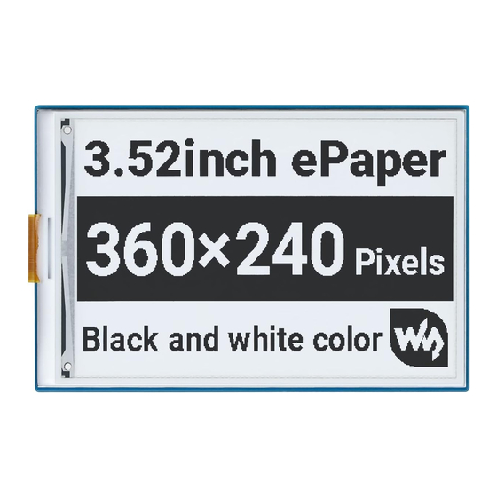
User Manual 1. OVERVIEW 3.52inch e-Paper V1.1 is an Active Matrix Electrophoretic Display (AM EPD), with interface and a reference system design. The 3.52” active area contains 240x360 pixels. The module is a TFT-array driving electrophoretic display, with integrated circuits including gate buffer, source buffer, MCU interface, timing control logic, oscillator, DC-DC, SRAM, LUT, VCOM. -
Page 5: Features
3.52inch e-Paper V1.1 User Manual 2. FEATURES 240×360 pixels display White reflectance above 30% Contrast ratio above 8:1 Ultra wide viewing angle Ultra low power consumption Pure reflective mode Bi-stable display Landscape and portrait modes ... -
Page 6: Mechanical Specifications
3.52inch e-Paper V1.1 User Manual 3. MECHANICAL SPECIFICATIONS Parameter Specification Unit Screen Size 3.52 Inch Display Resolution 240 (H) x 360 (V) Pixel Active Area 49.67 (H) x 74.51 (V) Pixel Pitch 0.207 (H) x 0.207 (V) Pixel Configuration Rectangle Outline Dimension 54.41 (H) ×... -
Page 7: Mechanical Drawing Of Epd Module
3.52inch e-Paper V1.1 User Manual 4. MECHANICAL DRAWING OF EPD MODULE Note: 1. Display module 3.52″ array for EPD; 2.Unspecified tolerance is ±0.20; 3. Materials confirm to RoHS standards; 4. The mark ✱ for control dimensions, ( ) for reference dimensions; 5. Product thickness includes: Top glass + EPL + PS. -
Page 8: Pin Assignment
3.52inch e-Paper V1.1 User Manual 5. PIN ASSIGNMENT Name Description Remark Do not connect with other NC pins N-Channel MOSFET Gate Drive Control RESE Current Sense Input for the Control Loop Do not connect with other NC pins VDHR Positive Source driving voltage 1... - Page 9 3.52inch e-Paper V1.1 User Manual - Outputting display waveform - Programming with OTP - Communicating with digital temperature sensor 5-4: Bus interface selection pin BS State MPU Interface 4-line serial peripheral interface(SPI) 3-line serial peripheral interface(SPI) - 9 bits SPI...
-
Page 10: Electrical Characteristics
3.52inch e-Paper V1.1 User Manual 6. ELECTRICAL CHARACTERISTICS 6.1 ABSOLUTE MAXIMUM RATING Parameter Symbol Rating Unit Logic supply voltage -0.5 to +4.0 Logic Input voltage -0.5 to Vdd +0.5 Logic Output voltage VOUT -0.5 to Vdd +0.5 Note: Maximum ratings are those values beyond which damages to the device may occur. -
Page 11: Panel Dc Characteristics(Driver Ic Internal Regulators)
3.52inch e-Paper V1.1 User Manual VDD=3.0V DC/DC Deep sleep mode Idslp_VD No clock current No output Load Ram data not retain Operation temperature TOPR °C range Operation illuminance Indoor only 2000 intensity Storage temperature TSTG °C range Storage relative humidity... -
Page 12: Panel Ac Characteristics
3.52inch e-Paper V1.1 User Manual 6.4 PANEL AC CHARACTERISTICS 6-4-1 MCU Interface Selection The MCU interface consists of 2 data/command pins and 3 control pins. The pin assignment at different interface modes is summarized in Table 6-4-1. Different MCU mode can be set by hardware selection on BS pins. -
Page 13: Mcu Serial Interface (3-Wire Spi)
3.52inch e-Paper V1.1 User Manual 6-4-3 MCU Serial Interface (3-wire SPI) The 3-wire serial interface consists of serial clock SCLK, serial data SDIN and CSB. In 3-wire SPI mode, SCL acts as SCLK, SDA acts as SDIN. The operation is similar to 4-wire serial interface while D/C pin is not used. There are altogether 9 bits will be shifted into the shift register on every ninth clock in sequence: D/C bit, D7 to D0 bit. - Page 14 3.52inch e-Paper V1.1 User Manual Figure 6-4-4: Serial interface characteristics Vdd - VSS = 2.4V to 3.3V, TOPR = 25°C, CL=20pF Parameter Symbol Min. Typ. Max. Unit tcycle Clock Cycle Time Address Setup Time Address Hold Time tCSS Chip Select Setup Time...
-
Page 15: Optical Specification
3.52inch e-Paper V1.1 User Manual 7. OPTICAL SPECIFICATION Measurements are performed when the illumination is under an angle of 45 degrees, and the detection results are obtained perpendicularly unless otherwise specified. Value Parameter Symbol Condition Unit Note Min. Typ. Max. -
Page 16: Handling, Safety, And Environment Requirements
3.52inch e-Paper V1.1 User Manual 8. HANDLING, SAFETY, AND ENVIRONMENT REQUIREMENTS 1. The EPD Panel / Module is manufactured from fragile materials such as glass and plastic, and may be broken or cracked if dropped. Please handle with care. Do not apply force such as bending or twisting to the EPD panel 2. -
Page 17: Reliability Test
3.52inch e-Paper V1.1 User Manual 9. RELIABILITY TEST Test Condition Method Remark At the end of the test, electrical, High-Temperature T = +50°C, RH = 30% for IEC 60 068-2- mechanical, and optical Operation 240 hrs specifications shall be satisfied... -
Page 18: Block Diagram
3.52inch e-Paper V1.1 User Manual 10. BLOCK DIAGRAM... -
Page 19: Typical Application Circuit With Spi Interface
3.52inch e-Paper V1.1 User Manual 11. TYPICAL APPLICATION CIRCUIT WITH SPI INTERFACE...


Need help?
Do you have a question about the 3.52inch e-Paper V1.1 and is the answer not in the manual?
Questions and answers