Advertisement
SERVICE MANUAL
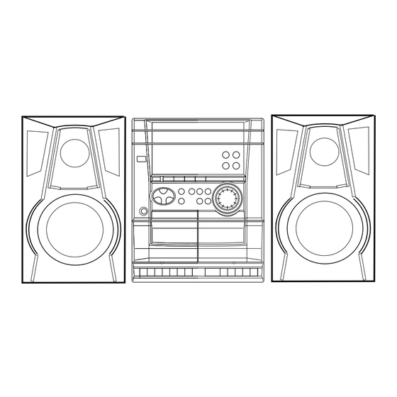
COMPACT DISC
STEREO CASSETTE RECEIVER
SYSTEM
NSX–DR2
NSX–DR3
• If requiring information about the CD mechanism, see Service Manual of AZG-1,
(S/M Code No. 09-001-335-3NC).
NSX-DR2
NSX-DR3
BASIC CD MECHANISM : AZG-1 ZA3RNM/ZA4RNC
BASIC TAPE MECHANISM : ZZM-2 PR1NM/PR1NC
CD
CASSEIVER
CX–NDR2
CX-NDR3
S/M Code No. 09-006-429-1N2
REMOTE
SPEAKER
CONTROLLER
SX–NSZ7
RC–ZAS02
SX–NSZ5
EZ (S)
EZ (S)
Advertisement
Table of Contents

Subscribe to Our Youtube Channel
Related Manuals for Aiwa NSX-DR2


Summary of Contents for Aiwa NSX-DR2
- Page 1 NSX-DR2 EZ (S) NSX-DR3 EZ (S) SERVICE MANUAL BASIC CD MECHANISM : AZG-1 ZA3RNM/ZA4RNC COMPACT DISC BASIC TAPE MECHANISM : ZZM-2 PR1NM/PR1NC STEREO CASSETTE RECEIVER REMOTE SYSTEM SPEAKER CASSEIVER CONTROLLER NSX–DR2 CX–NDR2 SX–NSZ7 RC–ZAS02 NSX–DR3 CX-NDR3 SX–NSZ5 • If requiring information about the CD mechanism, see Service Manual of AZG-1, (S/M Code No.
- Page 2 SPECIFICTAIONS Main unit Compact disc player section Laser Semiconductor laser (λ = 780 nm) FM tuner section D/A converter 1 bit dual Tuning range 87.5 MHz to 108 MHz Signal-to-noise ratio 85 dB (1 kHz, 0 dB) Usable sensitivity (IHF) 16.8 dBf Harmonic distortion 0.05% (1 kHz, 0 dB)
-
Page 3: Accessories List
ACCESSORIES LIST REF. NO PART NO. KANRI DESCRIPTION 1 8A-NFB-916-110 IB,EZ(9L)M -SZ7(RDS)<NDR2> 1 8A-NFB-918-010 IB,EZ(9L)S<NDR3> 2 87-A90-118-010 ANT,WIRE FM(Z) 3 87-A90-030-010 ANT,LOOP AM-NC C<NDR3> 3 87-006-225-010 ANT,LOOP ANT NC2<NDR2> 4 8Z-NF9-701-210 RC UNIT,ZAS02<NDR2> 4 8Z-NF9-702-010 RC UNIT,ZAS02<NDR3>... -
Page 4: Protection Of Eyes From Laser Beam During Servicing
PROTECTION OF EYES FROM LASER BEAM DURING SERVICING CAUTION This set employs laser. Therefore, be sure to follow carefully the instructions below when servicing. Use of controls or adjustments or performance of procedures other than those specified herein may result in hazardousradiation exposure. WARNING! ATTENTION WHEN SERVICING, DO NOT APPROACH THE LASER EXIT WITH THE... - Page 5 NOTE ON BEFORE STARTING REPAIR -1/2 1. Forced discharge of electrolytic capacitor of power supply block When repair is going to be attempted in the set that uses relay circuit in the power supply block, electric potential is kept charged across the electrolytic capacitors (C101, 102) even though AC power cord is removed.
- Page 6 NOTE ON BEFORE STARTING REPAIR -2/2 In such a case, check also if the POWER AMPLIFIER circuit or power supply circuit has any abnormalities or not. 2-2. Regarding reset There are cases that the machine does not work correctly because the MICROCOMPUTER is not reset even though the AC power cord is re- inserted, or the software reset (pressing the STOP key + POWER key) is performed.
- Page 7 ELECTRICAL MAIN PARTS LIST -1/3 REF. NO PART NO. KANRI DESCRIPTION REF. NO PART NO. KANRI DESCRIPTION C0106 87-010-186-080 C-CAP,S 4700P-50 K B C2012 C0107 87-010-403-080 CAP,E 3.3-50 M 11L SME C0108 87-010-403-080 CAP,E 3.3-50 M 11L SME 8A-NFA-615-010 C-IC,M38B57MCH-E236FP<NDR3> C0109 87-010-322-080 C-CAP,S 100P-50 J CH GRM...
- Page 8 ELECTRICAL MAIN PARTS LIST -2/3 REF. NO PART NO. KANRI DESCRIPTION REF. NO PART NO. KANRI DESCRIPTION C0606 87-010-179-080 C-CAP,S 1200P-50 K B GRM C0876 87-010-405-080 CAP,E 10-50 M 11L SME<NDR2> C0609 87-010-213-080 C-CAP,S 0.015-25 K B GRM C0877 87-010-197-080 C-CAP,S 0.01-25 K B C2012<NDR2>...
- Page 9 ELECTRICAL MAIN PARTS LIST -3/3 REF. NO PART NO. KANRI DESCRIPTION REF. NO PART NO. KANRI DESCRIPTION TC0942 87-A91-774-080 TRIMMER,PLY 30P 6.8X5.4 CDYL S0101 87-A91-555-010 SW,RTRY EC12E24504 WH0001 87-A90-460-010 HLDR,WIRE 2.5-7P S0301 87-A90-164-080 SW,TACT SKQNAB(N) X0861 87-A70-091-010 VIB,XTAL 4.332MHZ CSA-309<NDR2> S0302 87-A90-164-080 SW,TACT SKQNAB(N)
-
Page 10: Transistor Illustration
TRANSISTOR ILLUSTRATION E C B B C E 2SA1981 2SA1235 2SB1370 2SC5343 2SC2714 2SD2061 2SC3052 CSC4115 CSD1306 KTA1266 KRA102S KTC3198 KRA107S KRC102S KRC104S S D G 2SJ460 2SK302 2SK2541 2SK360 2SK882 -10-... - Page 16 WIRING - 3/4 (DECK SECTION) -16-...
- Page 17 SCHEMATIC DIAGRAM -4/4 (PT SECTION) -17-...
- Page 18 WIRING - 4/4 (PT C.B) W181 AC230V 50Hz (CHASSIS) -18-...
-
Page 19: Ic Block Diagram -1
IC BLOCK DIAGRAM -1/2 IC, LC72131D-N PHASE DETECTOR CHARGE PUMP POWER REFERENCE UNLOCK DIVIDER DETECTOR RESET SWALLOW COUNTER 1/16, 1/17 4BITS 12BITS PROGRAMMABLE DRIVER UNIVERSAL DATA SHIFT REGISTER LATCH INTERFACE COUNTER 2 3 4 5 6 7 8 9 IC, M62495AFP -19-... -
Page 20: Ic Block Diagram -2
IC BLOCK DIAGRAM -2/2 IC, LA1845L IC, BU1920FS 100kΩ — 8TH SWITCHED CAPACITOR FILTER Vref RCLK QUAR RESET DIFFERENTIAL BI-PHASE 57kHz RDATA 1187.5HZ DECODER DECODER RDS/ARI REFERENCE TEST CIRCUIT CLOCK -20-... - Page 21 IC DESCRIPTION -1/1 (M38B57MCH-E236FP/M38B59MFH-E251FP) -1/2 Pin No. Pin Name Description I-SIG RDS signal level A/D input. (Not used) ___________ I-HOLD Hold voltage level A/D input. I-SW (CD) CD mecha SW A/D input. I-DISH CD turn-table position check A/D input. I-KEY2 KEY2 A/D input.
- Page 22 IC DESCRIPTION -1/1 (M38B57MCH-E236FP/M38B59MFH-E251FP) -2/2 Pin No. Pin Name Description O-DISH_R CD turn-table reverse turn output. O-DISH_F CD turn-table forward turn output. I-SUBQ Sub code-Q data input. O-CD_CE CD DSP chip enable output. I-WRQ CD WRQ input. O-CLK (CD) CD control clock output . O-DATA (CD) CD control data output.
- Page 23 ADJUSTMENT -1/2 MAIN C.B 15 14 13 12 10 9 L801 TC942 L802 TP4 (DC BAL) L941 IC801 L951 L942 IC301 (DC BAL) (CLK) TP8 (LCH) TP1 (VT) TP9 (RCH) FFE831 DECK-1 R/P/E, DECK-2 P HEAD FRONT C.B IC101 L101 -23-...
- Page 24 ADJUSTMENT -2/2 < DECK SECTION > < TUNER SECTION > 10. Tape Speed Adjustment (DECK 1) 1. Clock Frequency Check Settings: • Test tape: TTA-100 Settings: • Test point: TP2 (CLK) • Test point: TP8 (Lch), TP9 (Rch) Method: Set to MW 1602kHz and check that the test point is •...
- Page 25 FL (10-BT-224GNK) GRID ASSIGNMENT/ANODE CONNECTION -1/2 GRID ASSIGNMENT -25-...
- Page 26 FL (10-BT-224GNK) GRID ASSIGNMENT/ANODE CONNECTION -2/2 ANODE CONNECTION -26-...
- Page 28 2 8A-NFA-004-010 BOX,CASS 2 3 8A-NFA-003-010 BOX,CASS 1 4 8A-NFA-007-010 WINDOW,CASS 2 5 8A-NFA-006-010 WINDOW,CASS 1 6 87-B00-002-010 BADGE,AIWA 30 ABS SIL<NDR3> 6 87-CE3-023-010 BADGE,AIWA 30N SILV<NDR2> 7 8A-NFB-004-010 WINDOW,DISP EZ DR2<NDR2> 7 8A-NFB-005-010 WINDOW,DISP EZ DR3<NDR3> 8 8A-NFA-011-110 KNOB,RTRY VOL...
-
Page 29: Color Name Table
COLOR NAME TABLE Basic color symbol Color Basic color symbol Color Basic color symbol Color Black Cream Orange Green Gray Blue Transparent Blue Gold Pink Silver Titan Silver Brown Violet White Transparent White Yellow Transparent Yellow Metallic Blue Light Blue Transparent Green Dark Blue Transparent Orange... - Page 31 TAPE MECHANISM PARTS LIST -1/1 (ZZM-2 PRINM/PRINC) REF. NO PART NO. KANRI DESCRIPTION REF. NO PART NO. KANRI DESCRIPTION 1 8Z-ZM1-254-210 SPR-C,REEL R 36 8Z-ZM1-220-110 LEVER,REC SENSOR 2 8Z-ZM1-225-110 GEAR,REEL R 37 8Z-ZM1-249-010 SPR-T,FR 3 8Z-ZM1-253-110 SPR-C,AUTO SENSOR 38 8Z-ZM1-242-110 SPR-T,FF/REW 4 8Z-ZM1-217-110 LEVER,AUTO SENSOR...
- Page 32 SPEAKER DISASSEMBLY INSTRUCTIONS Type.4 Type.1 Insert a flat-bladed screwdriver into the position indicated by the TOOLS arrows and remove the panel. Remove the screws of each speaker 1 Plastic head hammer unit andthen remove the speaker units. 2 (-) flat head screwdriver 3 Cut chisel Type.2 How to Remove the PANEL, FR...
- Page 33 SPEAKER PARTS LIST -1/1 REF. NO PART NO. KANRI DESCRIPTION 1 8A-NSL-001-010 PANEL,FR 2 8A-NSL-003-010 GRILLE,FRAME ASSY<EXCEPT NSZ7YSC1> 2 8A-NSL-021-010 GRILLE,FRAME ASSY L<NSZ7YSC1> 3 8Z-NSL-601-110 SPKR, W 120<NSZ5YSC9> 3 8A-NSL-606-010 SPKR, W 120<EXCEPT NSZ5YSC9,NSZ7YSC9> 3 8Z-NSL-603-010 SPKR, W 120<NSZ7YSC9> 4 87-NS7-611-010 CORD,SPKR<NSZ5YSC9,NSZ7YSC9>...
- Page 34 2–11, IKENOHATA 1–CHOME, TAITO-KU, TOKYO 110, JAPAN TEL:03 (3827) 3111 920074 Printed in Singapore...
Need help?
Do you have a question about the NSX-DR2 and is the answer not in the manual?
Questions and answers