Table of Contents
Advertisement
Quick Links
©2023 Lennox Industries Inc.
Dallas, Texas, USA
THIS MANUAL MUST BE LEFT WITH THE
HOMEOWNER FOR FUTURE REFERENCE
WARNING
Improper installation, adjustment, alteration, service
or maintenance can cause property damage, personal
injury or loss of life. Installation and service must be
performed by a licensed professional HVAC installer or
equivalent, or service agency.
CAUTION
As with any mechanical equipment, contact with sharp
sheet metal edges can result in personal injury. Take
care while handling this equipment and wear gloves and
protective clothing.
PACKING LIST
WARRANTY
CERTIFICATE
OUTDOOR UNIT
SETTING THE UNIT – Clearances
See NOTES
See
NOTES
See NOTES
RAST 6-PIN
CONNECTORS (2)
NOTES:
Service clearance of 30 in. (762 mm) must be maintained on one of
the sides adjacent to the control box.
Clearance to one of the other three sides must be 36 in (914 mm).
See
Clearance to one of the remaining two sides may be 12 in. (305mm)
NOTES
and the final side may be 6 in.(152 mm).
A clearance of 24 in. (610 mm) must be maintained between two units.
48 in. (1219 mm) clearance required on top of unit.
Control
Box
Page 1
INSTALLATION
INSTRUCTIONS
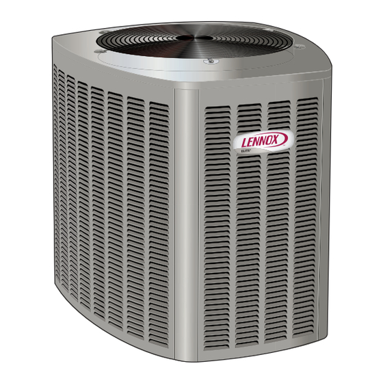
Elite
Series EL23XCV Units
®
AIR CONDITIONER
508273-01
9/2023
General
This EL23XCV outdoor air conditioner with all-aluminum
coil is designed for use with HFC-410A refrigerant only.
This unit must be installed with an approved indoor air han-
dler or coil. For AHRI Certified system match-ups and ex-
panded ratings, visit www.LennoxPros.com. The EL23XCV
variable capacity unit may be installed with an S30 commu-
nicating thermostat or a standard 24VAC non-communicat-
ing thermostat. See field wiring diagrams for wiring details.
These instructions are intended as a general guide and do
not supersede local codes in any way. Consult authorities
having jurisdiction before installation.
IMPORTANT: Special procedures are required for clean-
ing the all-aluminum coil in this unit. See page 20 in this
instruction for information.
WARNING
To prevent serious injury or death:
1. Lock-out/tag-out before performing maintenance.
2. If system power is required (e.g., smoke detector
maintenance), disable power to blower, remove fan
belt where applicable, and ensure all controllers
and thermostats are set to the "OFF" position before
performing maintenance.
3. Always keep hands, hair, clothing, jewelry, tools, etc.
away from moving parts.
Advertisement
Table of Contents

Related Manuals for Lennox Elite EL23XCV


Summary of Contents for Lennox Elite EL23XCV
- Page 1 INSTALLATION INSTRUCTIONS ©2023 Lennox Industries Inc. Elite Series EL23XCV Units Dallas, Texas, USA ® AIR CONDITIONER 508273-01 9/2023 General This EL23XCV outdoor air conditioner with all-aluminum coil is designed for use with HFC-410A refrigerant only. This unit must be installed with an approved indoor air han- dler or coil.
-
Page 2: Unit Dimensions - Inches (Mm)
UNIT DIMENSIONS – INCHES (MM) TOP VIEW C (depth) B (width) DISCHARGE AIR LIQUID LINE CONNECTION (height) ELECTRICAL INLETS SUCTION LINE CONNECTION 2 (51) 4−3/4 4−1/4(108) (121) 1 (25) SIDE VIEW END VIEW UNIT SUPPORT FEET Model Number EL23XCV-024 39 (991) EL23XCV-036 35-1/2 39-1/2... - Page 3 WARNING ELEVATED SLAB MOUNTING USING FEET EXTENDERS To prevent personal injury, as well as damage to panels, Use additional 2" SCH 40 male unit or structure, observe the following: 2" (50.8MM) SCH 40 threaded adapters which can FEMALE THREADED be threaded into the female While installing or servicing this unit, carefully stow all ADAPTER threaded adapters to make...
-
Page 4: Refrigerant Piping
Take to Service and Application Note - Corp. 9112-L4 (C-91-4). care to empty all existing traps. Polyvinyl ether (PVE) oils are used in Lennox variable-capacity units charged WARNING with HFC-410A refrigerant. Residual mineral oil can When using a high pressure gas such as act as an insulator, preventing proper heat transfer. - Page 5 COOLING SYSTEM (HFC410A) • Between 51 and 150 Linear Feet: Crankcase heater and nonbleed port TXV factory installed. No additional • Total equivalent length equals 180 feet (piping and all components required. Vertical vapor riser must be sized fittings included). to the vapor riser listed in the table 3 on systems with NOTE –...
- Page 6 REFRIGERANT PIPING – Removing Existing Indoor Metering Device TYPICAL EXISTING FIXED ORIFICE TYPICAL EXISTING EXPANSION VALVE REMOVAL REMOVAL PROCEDURE PROCEDURE (UNCASED COIL SHOWN) (UNCASED COIL SHOWN) STUB END TWO-PIECE PATCH PLATE LIQUID LINE CHECK DISTRIBUTOR TUBES (UNCASED COIL ONLY) ORIFICE EXPANSION LIQUID LINE ORIFICE HOUSING HOUSING...
-
Page 7: Cap And Core Removal
REFRIGERANT PIPING – Brazing Procedures CAP AND CORE REMOVAL CUT AND DEBUR Cut ends of the refrigerant lines square (free from nicks or dents) Remove service cap and core from and debur the ends. The pipe must remain round. Do not crimp end both the vapor and liquid line service of the line. -
Page 8: Braze Line Set
WRAP SERVICE VALVES To help protect service valve seals during brazing, wrap water-saturated cloths around service valve bodies and copper tube stubs. Use additional water-saturated cloths underneath the valve body to protect the base paint. FLOW NITROGEN Flow regulated nitrogen (at 1 to 2 psig) through the refrigeration gauge set into the valve stem port connection on the liquid service valve and out of the vapor valve stem port. - Page 9 REFRIGERANT PIPING – Install Indoor Expansion Valve This outdoor unit is designed for use in systems that include an expansion valve metering device (purchased separately) at the indoor coil. See the EL23XCV Product Specifications bulletin (EHB) for approved expansion valve kit match-ups and application information.
-
Page 10: Leak Test And Evacuation
LEAK TEST AND EVACUATION LEAK TEST HIGH MANIFOLD GAUGE SET OUTDOOR UNIT TO VAPOR SERVICE VALVE NOTE - Position canister to deliver liquid refrigerant. NITROGEN HFC-410A CONNECT GAUGE SET A - Connect the high pressure hose of an HFC-410A manifold gauge set to the vapor valve service port. NOTE - Normally, the high pressure hose is connected to the liquid line port. -
Page 11: Evacuate The System
EVACUATION HIGH CONNECT GAUGE SET NOTE - Remove cores from service valves (if not already done). A - Connect low side of manifold gauge set with 1/4 SAE in-line tee to vapor line service valve B - Connect high side of manifold gauge set to OUTDOOR MANIFOLD liquid line service valve... - Page 12 Take care three minutes to prevent compressor short cycling. The during unit installation and service to Lennox M30, CS7500, CS3000 and many other commer- protect the unit’s electronic controls. cially available electronic thermostats provide this feature. ELECTROSTATIC...
-
Page 13: Disconnect Switch
EL23XCV Thermostat Control Options Qty. of EL23XCV Field Wiring Thermostat Type Indoor Unit Type Wires to Terminal Strip Unit Operation Diagram EL23XCV Connections S30 Communicating Comunicating Gas Fully Communicating Variable Capacity R, I+, I-, C Figure 13 Thermostat Furnace or Air Handler Operation Based Upon Thermostat Demand Conventional 24VAC Any Furnace or Air... - Page 14 ROUTE CONTROL WIRES Communicating Thermostat Wiring Maximum length of wiring (18 gauge) for all connections on the RSBus is 1500 feet (457 meters). Wires should be color-coded, with º º a temperature rating of 95 F (35 C) minimum, and solid-core (Class II Rated Wiring). All low voltage wiring must enter unit through field-provided field-installed grommet installed in electrical inlet.
- Page 15 EL23XCV DATS (Optional) RAST 6-Pin Connectors OATS (Optional) Communicating Indoor Unit EL23XCV Outdoor Unit HD Display S30 Smart Hub Subbase or Mag-Mount PROVIDED RAST 6-PIN CONNECTOR INDOOR CONTROL Indoor Control Single Wire To C Terminal Single Wire To C Terminal Unused Wires Unused Wires FIGURE 13.
- Page 16 FIGURE 14. Conventional 24VAC Cooling Non-Communicating Thermostat Wiring Page 16...
- Page 17 5 – Outdoor Unitary Control - Jumpers and Terminals 7 SEGMENT DISPLAY CHARGE MODE JUMPER (CHRG MODE) CHARGE MODE AND OPERATION MODE JUMPER DETAIL OPERATION MODE JUMPER PUSH BUTTON RAST TERMINALS FOR THERMOSTAT WIRING CONNECTION EL23XCV Charge Mode Operation with a Convention- Outdoor Control 7 Segment Display and al 24VAC Non-Communicating Thermostat Push Button...
-
Page 18: Unit Operation
When the Operation Mode jumper is installed in the “Com- 3 - After evacuation is complete, open the liquid line and fort Mode” the suction pressure setpoint is 125 psig. vapor line service valve stems to release the refrigerant charge (contained in outdoor unit) into the system. Unit Operation 4 - Replace the stem caps and tighten to the value EL23XCV Unit Operation with a S30 Communicating... -
Page 19: Operating Angle-Type Service Valve
ACCESS SERVICE PORT OPERATING BALL-TYPE SERVICE VALVE A service port cap protects the service port core from contamination 1 - Remove stem cap with an appropriately sized wrench. and serves as the primary leak seal. 2 - Use an appropriately sized wrench to open. To open valve, rotate stem counterclockwise 90°. -
Page 20: Homeowners Information
This unit is equipped with an aluminum coil. • Have your Lennox dealer show you where your indoor Aluminum coils may be damaged by exposure to unit filter is located. It will be either at the indoor unit solutions with a pH below 5 or above 9. - Page 21 5 - Inspect contactor contacts for pitting or burn marks. 6 - Inspect the condition of the refrigerant lines and Replace as necessary. confirm that pipes are not rubbing copper-to- copper. Also, ensure that refrigerant pipes are not 6 - Check outdoor fan motor for worn bearings/ being affected by indoor air contamination.
-
Page 22: Start Up Checks
EL23XCV Start-Up and Performance Checklist Customer Address Indoor Unit Model Serial Outdoor Unit Model Serial Notes: START UP CHECKS Refrigerant Type: Rated Load Amps: Actual Amps Rated Volts Actual Volts Condenser Fan Full Load Amps Actual Amps: COOLING MODE Suction Pressure: Liquid Pressure: Supply Air Temperature: Ambient Temperature: Return Air: Temperature:...
Need help?
Do you have a question about the Elite EL23XCV and is the answer not in the manual?
Questions and answers