Advertisement
Table of Contents
- 1 Table of Contents
- 2 Shipping and Packing List
- 3 Outdoor Unit
- 4 Unit Dimensions, Corner Weights and Centers of Gravity
- 5 Unit Plumbing Parts Arrangement
- 6 Model Number Identification
- 7 Unit Control Box Components Arrangement
- 8 Rigging the Unit for Lifting
- 9 Installation Clearances
- 10 Line Set
- 11 Electrical Connections
- 12 Refrigerant Charge
- 13 System Operation
- 14 Maintenance
- Download this manual
THIS MANUAL MUST BE LEFT WITH THE
BUILDING OWNER FOR FUTURE REFERENCE
WARNING
Improper installation, adjustment, alteration, service
or maintenance can cause property damage, personal
injury or loss of life. Installation and service must be
performed by a licensed professional HVAC installer or
equivalent, or service agency.
IMPORTANT
The Clean Air Act of 1990 bans the intentional venting of
refrigerant (CFCs, HCFCs and HFCs) as of July 1, 1992.
Approved methods of recovery, recycling or reclaiming
must be followed. Fines and/or incarceration may be
levied for noncompliance.
CAUTION
As with any mechanical equipment, contact with sharp
sheet metal edges can result in personal injury. Take
care while handling this equipment and wear gloves and
protective clothing.
INSTALLATION
INSTRUCTIONS
Elite
ELS Series
®
6 - 20 Ton
AIR CONDITIONERS
6 - 20 TONS
507743-02
5/2019
Table of Contents
Shipping and Packing List .............................................1
Outdoor Unit ..................................................................1
Unit Plumbing Parts Arrangement ..................................5
Model Number Identification ........................................10
Unit Control Box Components Arrangement ................ 11
Rigging the Unit for Lifting ...........................................12
Installation Clearances ................................................13
Line Set .......................................................................13
Electrical Connections .................................................13
Refrigerant Charge ......................................................19
System Operation ........................................................21
Maintenance ................................................................21
Shipping and Packing List
Check the unit for shipping damage. If damaged or parts
are missing, immediately contact the last shipping carrier.
1 - Assembled outdoor unit
1 - Installation instructions
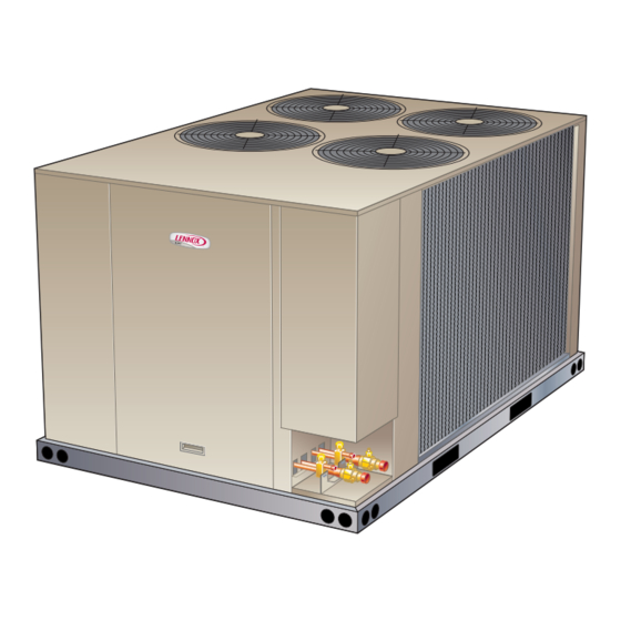
Outdoor Unit
ELS Series air conditioners, which will also be referred to
in this instruction as the outdoor unit, use HFC-410A re-
frigerant. This outdoor unit must be installed with a match-
ing indoor unit and line set as outlined in the ELS Series
Engineering Handbook.
This outdoor unit is designed for use in thermal expansion
valve (TXV) systems only.
Page 1
Advertisement
Table of Contents

Subscribe to Our Youtube Channel
Related Manuals for Lennox Elite ELS Series


Summary of Contents for Lennox Elite ELS Series
-
Page 1: Table Of Contents
INSTALLATION INSTRUCTIONS Elite ELS Series ® 6 – 20 Ton AIR CONDITIONERS 6 - 20 TONS 507743-02 5/2019 THIS MANUAL MUST BE LEFT WITH THE Table of Contents BUILDING OWNER FOR FUTURE REFERENCE Shipping and Packing List ..........1 WARNING Outdoor Unit ..............1 Unit Dimensions, Corner Weights and Centers of Gravity ...2 Improper installation, adjustment, alteration, service Unit Plumbing Parts Arrangement ........5... -
Page 2: Unit Dimensions, Corner Weights And Centers Of Gravity
Unit Dimensions, Corner Weights and Centers of Gravity ELS072S4S AND ELS090S4S Corner Weights Centers of Gravity Model No. Model No. lbs. lbs. lbs. lbs. inch inch 23.2 589.3 19.2 487.7 ELS072S4S ELS072S4S 20.3 515.6 ELS090S4S ELS090S4S INCHES (MM) OPTIONAL HAIL GUARD (Field Installed All Coil Sides) (Not used with... - Page 3 ELS120S4S, ELS120S4D AND ELS150S4D Corner Weight Centers of Gravity Model No. Model No. inch inch lbs. lbs. lbs. lbs. 20.5 33.5 ELS 120S4S ELS 120S4S 21.0 28.5 ELS 120S4D ELS 120S4D 19.0 30.0 ELS 150S4D ELS 150S4D OPTIONAL HAIL GUARD (Field Installed All Coil Sides) (Not used with Coil Guard) INLET AIR...
- Page 4 ELS180S4D AND ELS240S4D Corner Weight Centers of Gravity Model No. Model No. inch inch lbs. lbs. lbs. lbs. ELS180S4D ELS180S4D ELS240S4D ELS240S4D OPTIONAL HAIL GUARD (Field Installed All Coil Sides) (Not used with Coil Guard) OUTDOOR FAN 9−1/8 INLET LIQUID (232) GUARDS (4) LINE (2)
-
Page 5: Unit Plumbing Parts Arrangement
Unit Plumbing Parts Arrangement ELS072S4S ELS090S4S Page 5... - Page 6 ELS120S4S ELS120S4D – STAGE 2 Page 6...
- Page 7 ELS120S4D – STAGE 1 ELS150S4D – STAGE 2 Page 7...
- Page 8 ELS150S4D – STAGE 1 ELS180S4D – STAGE 2 Page 8...
- Page 9 ELS180S4D – STAGE 1 ELS240S4D – STAGE 2 Page 9...
-
Page 10: Model Number Identification
ELS240S4D – STAGE 1 Model Number Identification E L S 120 S Brand/Family Voltage Elite™ Product Line Y = 208/230V 3 phase 60hz G = 460V 3 phase 60hz J = 575V 3 phase 60hz M = 380/420V 3 phase 50hz Minor Design Sequence 1 = 1st Revision S = Split System Air Conditioner... -
Page 11: Unit Control Box Components Arrangement
Unit Control Box Components Arrangement Page 11... -
Page 12: Rigging The Unit For Lifting
Rigging the Unit for Lifting Lifting point should be directly above the center of gravity. Caution - do not walk on unit Rig the unit for lifting by attaching four cables to the holes in the base rail of the unit. See figures 1 through 3. 1 - Remove protective packaging before rigging the unit for lifting. -
Page 13: Installation Clearances
1 (excluding equivalent length of fittings). Size refrigerant lines greater than 50 linear feet FIGURE 5. ELS120S4S, ELS120S4D (15m or greater) according to the Lennox Refrigerant Pip- and ELS150 Installation Clearances ing Design and Fabrication Guidelines (Corp. 9351-L9) or latest version. - Page 14 TRANSFORMER – 24V INSTALL THERMOSTAT Use the transformer provided with the air conditioning unit for low-voltage control power (24V, 70VA) NOTE – The addition of accessories to the system could exceed the 70VA power requirement of the factory-pro- vided transformer. Measure the system’s current and voltage after installation is complete to determine trans- former loading.
- Page 15 TYPICAL UNIT CONTROL WIRE CONNECTIONS WIRE RUN LENGTH AWG# INSULATION TYPE LESS THAN 100’ (30M) TEMPERATURE RATING MORE THAN 100’ (30M) 35°C MINIMUM RUN CONTROL WIRES THROUGH RIGHT CUTOUT. RUN CONTROL WIRES THROUGH WIRE TIES. MAKE CONTROL WIRE CONNECTIONS USING FIELD PROVIDED WIRE NUTS.
- Page 16 FIGURE 7. Typical Wiring Diagram – ELS072S4S, ELS090S4S and ELS120S4S (G, J, M, Y Voltages) Page 16...
- Page 17 TB14 COOL 2 COOL 1 TB14 LINE VOLTAGE FIELD INSTALLED DENOTES OPTIONAL COMPONENTS CIRCUIT BREAKER-TRANS T1 SWITCH-LOSS OF CHARGE,COMP 1 SWITCH-LOSS OF CHARGE,COMP 2 TRANSFORMER-CONTROL TERMINAL STRIP-CLASS II VOLTAGE TB14 K10,-1 K66,-1,2 WIRING DIAGRAM 08/17 K67,-1,2 ELS-120,150-G,J,M,Y SECTION A 3 REV.
- Page 18 TB14 COOL 2 COOL 1 TB14 SWITCH-LOSS OF CHARGE,COMP 1 SWITCH-LOSS OF CHARGE,COMP 2 TRANSFORMER-CONTROL TB14 TERMINAL STRIP-CLASS II VOLTAGE DENOTES OPTIONAL COMPONENTS LINE VOLTAGE FIELD INSTALLED K10,-1 K66,-1,2 K67,-1,2 K149,-1 CIRCUIT BREAKER-TRANS T1 08/17 WIRING DIAGRAM SINGLE SPEED COMPRESSOR ELS-180,240-G,J,M,Y SECTION A 4 REV.
-
Page 19: Refrigerant Charge
2 - Add refrigerant to each circuit based on measured Refrigerant Charge liquid and suction line lengths. ELS units have a factory holding charge of 2 pounds of A - If the measured line length is greater than 25 feet, HFC-410A in each circuit. - Page 20 TABLE 3. Approach Temperatures – Commercial Matchups Models Approach Temperature Outdoor Indoor Stage (ºF) (+/- 1) (ºC) (+/- 0.5) ELS072S4S ELA072S4S ELS090S4S ELA090S4D ELS120S4S ELA120S4D ELS120S4D ELA120S4D ELS150S4D ELA150S4D ELS180S4D ELA180S4D ELS240S4D ELA240S4D TABLE 4. Normal Operating Pressures – Cooling – Single Stage – Commercial* ELS120S4S + Entering ELS072 + ELA072...
- Page 21 Entering ELS150 + ELA180 ELS180 + ELA180 Outdoor Air STAGE 1 STAGE 2 STAGE 1 STAGE 2 Temp Liquid Suction Liquid Suction Liquid Suction Liquid Suction ºF (ºC) 65 (18) 75 (24) 85 (29) 95 (35) 105 (41) 115 (46) 125 (52) SCFM 5150...
- Page 22 TABLE 7. Normal Operating Pressures* – Single and Two Stage – Residential Entering Outdoor ELS090 + (2) CX35-060C ELS090 + (2) CX35-060D Air Temp STAGE 1 STAGE 1 ºF (ºC) ºF (ºC) Liquid Suction Liquid Suction 65 (18) 75 (24) 85 (29) 95 (35) 105 (41)
-
Page 23: System Operation
3 - Visually inspect connecting lines and coils for System Operation evidence of oil leaks. The outdoor unit and indoor blower cycle on demand from 4 - Check wiring for loose connections. the room thermostat. When the thermostat blower switch 5 - Check for correct voltage at the unit while the unit is is in the ON position, the indoor blower operates contin- operating and while it is off. - Page 24 Start-Up and Performance Checklist Job Name Job no. Date Job Location City State Installer City State Unit Model No. Serial No. Service Technician Nameplate Voltage Rated Load Ampacity Compressor Amperage: Maximum Fuse or Circuit Breaker Electrical Connections Tight? Indoor Filter clean? Supply Voltage (Unit Off) Indoor Blower RPM S.P.
Need help?
Do you have a question about the Elite ELS Series and is the answer not in the manual?
Questions and answers