
Subscribe to Our Youtube Channel
Related Manuals for Q'STRAINT QUANTUM


Summary of Contents for Q'STRAINT QUANTUM
- Page 1 INSTALLATION & USER MANUAL THE QUANTUM SECUREMENT SYSTEM MEETS ALL CURRENT REGULATIONS FOR REAR FACING TRANSIT, ® EUROPEAN DIRECTIVES AND ADA/CSA REQUIREMENTS.
- Page 2 © 2022 Q’STRAINT®. All Rights Reserved. Q’STRAINT®, Q’STRAINT® logo and QUANTUM® are registered trademarks of Q’STRAINT®, Inc. Products mentioned herein are for identification purposes only and may be registered trademarks or trademarks of their respective companies. All other brand names, trademarks or registered trademarks...
-
Page 3: Table Of Contents
TABLE OF CONTENTS IMPORTANT SAFEGUARDS AND WARNINGS ........4 QUANTUM SECUREMENT SYSTEM OVERVIEW ......5 QUANTUM SECUREMENT SYSTEM LAYOUT ........6 ELECTRICAL REQUIREMENTS ............... 7 MOUNTING REQUIREMENTS ............... 8 OCCUPANT RESTRAINT ................9 STANCHION ....................10 MANUAL RELEASE (ROTATIONAL AND NON-ROTATIONAL CONFIGURATION) ..11 SYSTEM OPERATION ................12... -
Page 4: Important Safeguards And Warnings
OPTIMIZE WHEELCHAIR LOCATION AND CONFIGURATION! The Wheeled Mobility Device must be located at the center of the QUANTUM® station with the rear part of the wheelchair placed firmly against the Backrest so to maximize the contact area between the QUANTUM® Rotational and Non-Rotational arm grips and the Wheeled Mobility Device wheel surface. -
Page 5: Quantum Securement System Overview
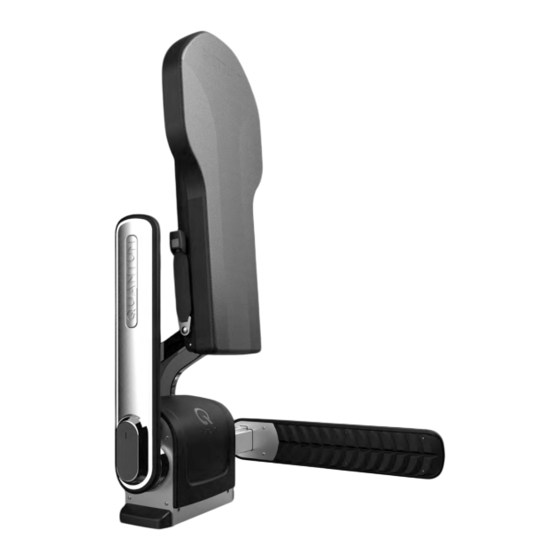
QUANTUM SECUREMENT SYSTEM OVERVIEW 1. QUANTUM BASE 2. BACKREST 3. OCCUPANT RESTRAINT 4. STOWAGE 5. OCCUPANT INTERFACE 6. DRIVER INTERFACE 7. WHEELED MOBILITY DEVICE QUANTUM (ROTATIONAL RIGHT) QUANTUM (ROTATIONAL LEFT) QUANTUM (NON-ROTATIONAL) Wall Wall Wall Wall Wall Wall Wall Wall... -
Page 6: Quantum Securement System Layout
QUANTUM SECUREMENT SYSTEM LAYOUT Do NOT Install two (2) QUANTUM® Securement Systems side by side unless a minimum aisle pathway of 22” (560 MM) can be achieved when the QUANTUM® arms of both units are fully extended. -
Page 7: Electrical Requirements
ELECTRICAL REQUIREMENTS 1. Power source of 12VDC (11VDC-16VDC) at 15 amps or 24 VDC (20VDC-32.5VDC) at 10 Amps using 12 AWG. 2. Ignition signal of 12 VDC or 24VDC using 20 AWG. 3. Parking brake signal of 12VDC or 24 VDC using 20 AWG. 4. -
Page 8: Mounting Requirements
QUANTUM® (B) & (C) using supplied hardware. QUANTUM® connector as shown below. 3. Install QUANTUM system (A) to the Mounting 4. Install the Base Feet (A) on the QUANTUM base. plate (B), Install backrest Cover (C), using supplied hardware. Recommended torque 15FT/LB (20.3 Nm). -
Page 9: Occupant Restraint
6” (152mm) OCCUPANT RESTRAINT 04mm) 6” (152mm) 1. The Occupant Securement Retractor (shoulder and 2. Remove the 3 screws, lock washers and washers on 6” (152mm) lap belt) must be 48” (1219mm) from the floor, 6” the upper rear side of the backrest. 6”... -
Page 10: Stanchion
QUANTUM® Backrest Stanchion Support MUST be installed with a maximum 45 Degree from horizontal. A. Carefully puncture the 2 outer holes on the top backside of the QUANTUM® Backrest. B. Align the 2 holes on the Adjustable Cup Fitting with the holes on the Backrest. -
Page 11: Manual Release
MANUAL RELEASE REMOVE POWER SOURCE BEFORE PERFORMING MANUAL RELEASE ROTATIONAL NON-ROTATIONAL 1. Remove cover by turning groove clockwise. 1. Remove cover by turning groove clockwise. 2. Pull and rotate release handle Counter-clockwise to 2. Press in logo plate to disengage arm. release arm. -
Page 12: System Operation
QUANTUM re¬set switch Activate Reset Switch Reset Switch Reset Switch must be set to ON. Activate Activate QUANTUM is at Stowed Activate Reset Switch position. Activate 2. CAPTURE Have occupant maneuver User must be centered for ease into the securement area of securement. -
Page 13: Maintenance And Service Checklist
Service the QUANTUM System every 10,000 cycles. Once the QUANTUM® reaches 9,500 cycles, every time the vehicle is turned “ON” 2 Alert Beeps will be heard for 1 minute indicating that the QUANTUM® needs to be serviced soon. The QUANTUM® will still be operational. Make sure to con¬tact your authorized Q’STRAINT®... -
Page 14: Warranty
Q’STRAINT or its authorized dealers reserves the right to inspect the QUANTUM to verify the claimed defect has not been caused by non-Q’STRAINT- Approved maintenance or by foreign particles or substances. - Page 16 This manual was printed on 30% post-consumer stock using vegetable oil based inks and is 100% recyclable. © 2022 Q’STRAINT®. All Rights Reserved. QUANTUM® is a registered trademark of Q’STRAINT®, Inc. FOR TECHNICAL SUPPORT OR TO FIND YOUR NEAREST AUTHORIZED DEALER: Q’STRAINT Europe...
Need help?
Do you have a question about the QUANTUM and is the answer not in the manual?
Questions and answers