
Related Manuals for Q'STRAINT QER-4000


Summary of Contents for Q'STRAINT QER-4000
- Page 1 User Instructions Electrical Retractor Covers all Electrical Retractors for front wheelchair tie-downs PLEASE LEAVE THESE INSTRUCTIONS IN THE VEHICLE OR SEND THEM ON WITH THE OWNER OPERATOR.
-
Page 2: Table Of Contents
ELECTRICAL RETRACTOR USER INSTRUCTIONS This document is a comprehensive product user instruction; care must be taken to always be aware of your surroundings when installing this product. The Electrical Retractors are designed and tested to be used in the front positions ONLY within the Q’Straint four point securment systems. -
Page 3: General Information & Product Description
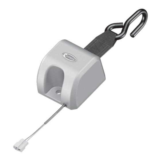
GENERAL INFORMATION Q’Straint introduces QER-4000, the world’s rst 4m front electrical locking retractor for the easy securement of wheelchairs in vehicles. Q’Straint’s QER-4000 4-Point wheelchair & occupant securement systems, when used as recommended, provide the safest means of transportation for wheelchair passengers unable to transfer from their wheelchairs when traveling in motor vehicles. -
Page 4: Warnings, Notes And Important Information
WARNINGS, NOTES AND IMPORTANT INFORMATION This guide is provided to assist with the installation of securement system components into vehicles’ oors and walls. If you have any questions or problems relating to your installation, please contact your nearest Q’Straint o ce. •... -
Page 5: Floor Anchorage Layout Recommendations
FLOOR ANCHORAGE LAYOUT RECOMMENDATIONS The following are the recommended best installation practices and distances (center-to-center) between oor anchorages (Figure 1). Recommended distances are based on common wheelchair sizes. Exceptionally large or small wheelchairs may require anchorage spacing that di ers from our recommendations. Consider optimal tie-down angles to determine exact placement of oor anchorages (Figure 2). - Page 6 USER INSTRUCTIONS CONT... Place the J-hook onto a solid frame member at the front of wheelchair or mobility aid, taking into account the proper angles needed (Figure 2). Turn o the power to the Electrical Retractors. Doing this will allow the webbing to self tension back into the retractors as the wheelchair is moved into the vehicle and will allow them lock so that the wheelchair or mobility device will not move (roll) back down the ramp.
-
Page 7: Removing The Wheelchair Or Mobility Aid From The Vehicle
Lap belt should bear upon the bony structure of the wheelchair occupant’s body and must never infringe on any component of the wheelchair such as armrests, panels, wheels, frames, etc. DIAGONAL SHOULDER RESTRAINT PELVIC RESTRAINT Belt restraints must not be held away from the body by wheelchair components such as armrests or wheels REMOVING THE WHEELCHAIR OR MOBILITY AID FROM THE VEHICLE Ensure the vehicle is parked on a suitable rm and level surface, taking care to not have too great of an incline and with... -
Page 8: Power Failure Procedure
POWER FAILURE PROCEDURE Removing the wheelchair or mobility aid; in the unlikely event of power failure. Should there be a power failure, it will not be possible to unlock the Electric Retractors. In the unlikely event that this happens the following instructions should be followed. Follow the above instructions in the section called Removing the Wheelchair or Mobility Aid from the Vehicle, up to number 5. -
Page 9: Warnings, Maintenance & Care
WARNINGS • Do not alter or modify the system or components in any way without rst consulting Q’Straint. • The system is a complete, integrated system. Do not interchange or substitute any components. • Q’Straint systems and components have been tested in a con guration similar to that recommended in these instructions. Any deviation from these recommendations is the responsibility of the installer. - Page 10 qstraint.com This guide contains current information at time of printing. Q’Straint reserves the right to modify systems, components or content without notice. Q’Straint Europe Q’Straint America Q’Straint Australia 4031 NE 12th Terrace 72-76 John Wilson Business Park Tramanco Pty Ltd. Oakland Park, FL 33334 Whitstable, Kent, CT5 3QT 21 Shoebury Street,...
Need help?
Do you have a question about the QER-4000 and is the answer not in the manual?
Questions and answers