Table of Contents
Advertisement
Quick Links
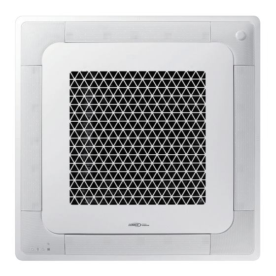
VRF (Variable Refrigerant Flow)
Installation manual
V33C***S4-4P
• Thank you for purchasing this Lennox Product.
• Before operating this unit, please read this manual carefully and retain it for future reference.
DB68-13132A-00_IM_VRF 4way_AA_EN_.indd 1
DB68-13132A-00_IM_VRF 4way_AA_EN_.indd 1
2024-07-30 오후 2:01:10
2024-07-30 오후 2:01:10
Advertisement
Table of Contents

Related Manuals for Samsung LENNOX V33C S4-4P Series


Summary of Contents for Samsung LENNOX V33C S4-4P Series
- Page 1 VRF (Variable Refrigerant Flow) Installation manual V33C***S4-4P • Thank you for purchasing this Lennox Product. • Before operating this unit, please read this manual carefully and retain it for future reference. DB68-13132A-00_IM_VRF 4way_AA_EN_.indd 1 DB68-13132A-00_IM_VRF 4way_AA_EN_.indd 1 2024-07-30 오후 2:01:10 2024-07-30 오후...
- Page 2 Contents Safety Information Safety Information Installation Procedure Installation Procedure Step 1 Checking and preparing accessories Step 2 Choosing the installation location Step 3 Optional: Insulating the body of the indoor unit Step 4 Installing the indoor unit Step 5 Purging inert gas from the indoor unit Step 6 Cutting and flaring the pipes Step 7 Connecting the assembly pipes to the refrigerant pipes Step 8 Performing the gas leak test...
-
Page 3: Safety Information
Safety Information California Proposition 65 Warning (US) • The 4-Way Cassette should be used only for the applications for which it has been designed: the indoor unit WARNING : is not suitable to be installed in areas used for laundry. Cancer and Reproductive Harm - www.P65Warnings.ca.gov. -
Page 4: Power Supply Line, Fuse Or Circuit Breaker
Safety Information Safety Information • Upon receipt, inspect the product to verify that it has not been • Always verify that electric connections (cable entry, damaged during transport. If the product appears damaged, section of leads, protections…) are compliant with DO NOT INSTALL it and immediately report the damage to the the electric specifications and with the instructions carrier or retailer (if the installer or the authorized technician... -
Page 5: Installation Procedure
Installation Procedure Step 1 Checking and preparing Step 2 Choosing the installation accessories location The following accessories are supplied with the indoor unit. The type and quantity may differ, depending on the Installation location requirements specifications. • There must be no obstacles near the air inlet and outlet. - Page 6 Installation Procedure (Unit: inch (mm)) 35.04~35.83 (890~910) (Celling opening) 37.4 (950) 28.94 (735) (Space of suspension bolts) 14.57 (370) 7.28 (185) 33.07 (840) 3.62 (92) 2.17 (55) 9.45 (240) 2.36 (60) 2.17 (55) 6.54 (166) 12.99 (330) 9.33 (237) 11.89 (302) 13.82 (351) The sub duct hole is not applicable to the Wind-Free models.
-
Page 7: Spacing Requirements
Spacing requirements 59.1 inch (1500 mm) or more 0.67 inch (17 0.79 inch 20 mm 98.43 inch (2500 mm) or more (20 mm) Obstruction Step 3 Optional: Insulating the body of the indoor unit Unit: inch (mm) If you install a cassette type indoor unit on the ceiling V33C006S4-4P when temperature is over 80.6 °F (27 °C) and humidity V33C009S4-4P... -
Page 8: Step 4 Installing The Indoor Unit
Installation Procedure Step 4 Installing the indoor unit CAUTION When deciding on the location of the 4-Way Cassette the • Make sure that the ceiling is strong enough to support following restrictions must be taken into account. the weight of the indoor unit. Before hanging the unit, test the strength of each attached suspension bolt. -
Page 9: Step 5 Purging Inert Gas From The Indoor Unit
Step 6 Cutting and flaring the pipes 7 Adjust the unit to the appropriate position, taking into account the installation area for the front panel. 1 Make sure that you have the required tools available: • Place the pattern sheet on the indoor unit. pipe cutter, reamer, flaring tool, and pipe holder. -
Page 10: Step 7 Connecting The Assembly Pipes To The Refrigerant Pipes
Installation Procedure 5 Check that the flaring is correct, referring to the Outer Diameter (inch (mm)) Torque (N•m) illustrations below for examples of incorrect flaring. Ø1/4 inch (6.35 mm) 14 to 18 Ø3/8 inch (9.52 mm) 34 to 42 Ø1/2 inch (12.70 mm) 49 to 61 Ø5/8 inch (15.88 mm) 68 to 82... -
Page 11: Step 8 Performing The Gas Leak Test
Step 8 Performing the gas leak test 2 Wind insulating tape around the pipes and drain hose avoiding compressing the insulation too much. To identify potential gas leaks on the indoor unit, inspect the connection area of each refrigerant pipe using a leak Insulation cover pipe Insulation cover pipe detector for R-410A. -
Page 12: Step 10 Installing The Drain Hose And Drain Pipe
Installation Procedure 5 Select the insulation of the refrigerant pipe. • Refrigerant pipe before EEV kit and MSB or without EEV kit and MSB • Insulate the gas side and liquid side pipe, noting the insulation thickness that must differ according –... - Page 13 Support pieces CAUTION 3.28 to 4.92 ft (1 to 1.5 m) Check that the indoor unit is level with the ceiling by using the leveller. 1/100 or more • Install air ventilation to drain condensation smoothly. Ceiling Air ventilation Air ventilation •...
-
Page 14: Step 11 Performing The Drainage Test
Installation Procedure 3.28 to 4.92 ft Hanger Hanger 1~1.5m Main air vent (1 to 1.5 m) Main air vent Individual air Individual 7.87 inch (200 mm) vent 200 mm or more air vent or more 11.81 inch (300 mm) to 300 to 550 mm 21.65 inch (550 mm) Centralized horizontal drainpipe... -
Page 15: Step 12 Connecting The Power And Communication Cables
• Tighten the electric wires with a proper tool within the CAUTION torque limit to connect and fix them firmly, and then organize the wires to prevent outside pressure being • When the float switch is not detected due to exerted on the covers and other parts. - Page 16 Installation Procedure Outdoor Unit Outdoor Unit Wired Remote Wired Remote Control Control 220~240V~ 208 - 230 V~ MCCB EEV kit EEV kit Indoor Unit 1 Indoor Unit 2 Indoor Unit 3 Indoor Unit 1 Indoor Unit 2 Indoor Unit 3 ※...
- Page 17 Norminal Norminal dimensions dimensions Standard Standard Standard Standard for cable Allowance Allowance for screw dimension dimension Allowance dimension dimension Allowance (inch² (inch (inch Min. Min. Max. Min. (inch (mm)) (inch (inch (inch (mm)) (inch (inch (inch (mm)) (mm)²) (mm)) (mm)) (mm)) (mm)) (mm))
- Page 18 Installation Procedure Example of Installation Total power cable length L = 328.08 [ft. ] (100 [m]), Initial pull-in current = 10[A], Running current of each units = 1[A], Total 10 indoor units were installed 10 [A] 9 [A] 1 [A] MCCB+ELB ELCB Indoor unit 1...
- Page 19 Step 13 Setting the indoor unit d Make sure that you are entered to the mode for setting options. addresses and the installation options You cannot set both indoor unit addresses and the installation options in a batch: set both respectively. 2 Digit Common steps for setting the addresses and options...
- Page 20 Installation Procedure Take the steps presented in the following table: Steps Remote control display 1 Set the SEG2 and SEG3 values: a Set the SEG2 value by pressing the button repeatedly until the value you want to set appears on the remote control display. SEG2 b Set the SEG3 value by pressing the button repeatedly until the value you...
- Page 21 Steps Remote control display 5 Set the SEG6 and SEG8 values: a Set the SEG6 value by pressing the button repeatedly until the value you want to set appears on the remote control display. SEG6 b Set the SEG8 value by pressing the button repeatedly until the value you want to set appears on the remote control display.
- Page 22 Installation Procedure Steps Remote control display 9 Set the SEG11 and SEG12 values: a Set the SEG11 value by pressing the button repeatedly until the value you want to set appears on the remote control display. SEG11 b Set the SEG12 value by pressing the button repeatedly until the value you want to set appears on the remote control display.
- Page 23 Steps Remote control display 14 Press the button to move to next page. 15 Set the SEG18 and SEG20 values: a Set the SEG18 value by pressing the button repeatedly until the value you want to set appears on the remote control display. SEG18 b Set the SEG20 value by pressing the button repeatedly until the value you...
- Page 24 Installation Procedure Steps Remote control display 19 Set the SEG23 and SEG24 values: a Set the SEG23 value by pressing the button repeatedly until the value you want to set appears on the remote control display. SEG23 b Set the SEG24 value by pressing the button repeatedly until the value you want to set appears on the remote control display.
- Page 25 Setting the indoor unit addresses (MAIN/MSB) 1 Make sure that the power is supplied to the indoor unit. • If the indoor unit is not plugged in, it must include a power supply. 2 Make sure that the panel or display is connected to the indoor unit so that it can receive options. Indoor unit Indoor unit 3 Set an address (MAIN/MSB port) for each indoor unit using the remote control, according to your air conditioning...
- Page 26 Installation Procedure Option SEG7 SEG8 SEG9 SEG10 SEG11 SEG12 Setting RMC Group channel Function Page Group address address (x16) Indication Details Indication Details Indication Details Indication Details No RMC address Indication and details RMC1 0 to F RMC2 0 to F address setting mode...
- Page 27 Installation options for the 02 series SEG1 SEG2 SEG3 SEG4 SEG5 SEG6 Use of external room temperature FAN RPM Evaporator Drying sensor / Minimizing Use of central control compensation fan operation when thermostat is off SEG7 SEG8 SEG9 SEG10 SEG11 SEG12 Dew removal Use of hot water...
- Page 28 Installation Procedure 02 series installation option (Detailed) Option No. : 02XXXX-1XXXXX-2XXXXX-3XXXXX Option SEG1 SEG2 SEG3 SEG4 SEG5 SEG6 Use of external room temperature sensor / Use of central Explanation PAGE MODE Evaporator Drying FAN RPM compensation Minimizing fan operation when thermostat is off control Details Use of...
- Page 29 Option SEG13 SEG14 SEG15 SEG16 SEG17 SEG18 Setting the output of external control / External heater signal / Explanation PAGE Use of external control S-Plasma ion Buzzer control Hours of filter usage Cooling operation signal / Free Cooling control signal Indication Details Indication Details Indication...
- Page 30 Installation Procedure (*3) 1: Fan is turned on continually when the hot water heater is turned on, 3: Fan is turned off when the hot water heater is turned on with cooling only indoor unit. (*4) When the following 2 or 3 is used as external heater On/Off signal, the signal for monitoring external contact control will not be output.
- Page 31 05 series installation option SEG1 SEG2 SEG3 SEG4 SEG5 SEG6 Use of Auto Change (When setting SEG3) Over for HR only in (When setting SEG3) (When setting SEG3) Standard for mode Auto mode / Use of Standard heating temp Standard cooling change Heating →...
- Page 32 Installation Procedure 05 series installation option (Detailed) Option No. : 05XXXX-1XXXXX-2XXXXX-3XXXXX Option SEG1 SEG2 SEG3 SEG4 SEG5 SEG6 Use of Auto Change Over (When setting SEG3) (When setting SEG3) (When setting SEG3) for HR only in Auto mode / Explanation PAGE MODE Standard heating temp...
- Page 33 Option SEG13 SEG14 SEG15 SEG16 SEG17 SEG18 Explanation Control variables when using hot water / external heater (*4) Details Indication Details Indication Set temp for heater On/Off Delay time for heater On At the same time as thermo on No delay At the same time as thermo on 10 minutes At the same time as thermo on...
- Page 34 Installation Procedure (*1) Height difference : The difference of the height between the corresponding indoor unit and the indoor unit installed at the lowest place. For example, When the indoor unit is installed 131.23ft. (40m) higher than the indoor unit installed at the lowest place, select the option “1”.
-
Page 35: Changing The Addresses And Options Individually
Changing the addresses and options individually When you want to change the value of a specific option, refer to the following table and follow the steps in Common steps for setting the addresses and options on page 20. Option SEG1 SEG2 SEG3 SEG4... -
Page 36: Performing Final Check And Trial Operation
Installation Procedure Performing final check and trial operation To complete the installation, perform the following checks and tests to ensure that the 4-Way Cassette operates correctly. 1 Check the followings. • Strength of the installation site • Tightness of pipe connection to detect a gas leak •... -
Page 37: Troubleshooting
Troubleshooting LED Display Operation Defrost Timer Filter Abnormal condition Error code Error on indoor temperature sensor (Short or Open) E121 1. Error on Eva-in sensor (Short or Open) E122 2. Error on Eva-out sensor (Short or Open) E123 3. Discharge sensor error (Short or Open) E126 Indoor fan error E154... - Page 38 Troubleshooting LED Display Operation Defrost Timer Filter Abnormal condition Error code 1. COND mid sensor is detached E241 2. Refrigerant leakage (2nd detection) E554 3. Abnomally high temperature on Cond (2nd detection) E450 4. Low pressure s/w (2nd detection) E451 5.
- Page 39 The amount of additional refrigerant The amount of additional refrigerant for each indoor unit. Model Charging additional refrigerant[kg (lb)] V33C006S4-4P V33C009S4-4P 0.6 (1.32) V33C012S4-4P V33C018S4-4P 0.73 (1.61) V33C024S4-4P V33C030S4-4P V33C036S4-4P 0.88 (1.94) V33C048S4-4P English DB68-13132A-00_IM_VRF 4way_AA_EN_.indd 39 DB68-13132A-00_IM_VRF 4way_AA_EN_.indd 39 2024-07-30 오후...
- Page 40 DB68-13132A-00_IM_VRF 4way_AA_EN_.indd 40 DB68-13132A-00_IM_VRF 4way_AA_EN_.indd 40 2024-07-30 오후 2:01:20 2024-07-30 오후 2:01:20...
Need help?
Do you have a question about the LENNOX V33C S4-4P Series and is the answer not in the manual?
Questions and answers