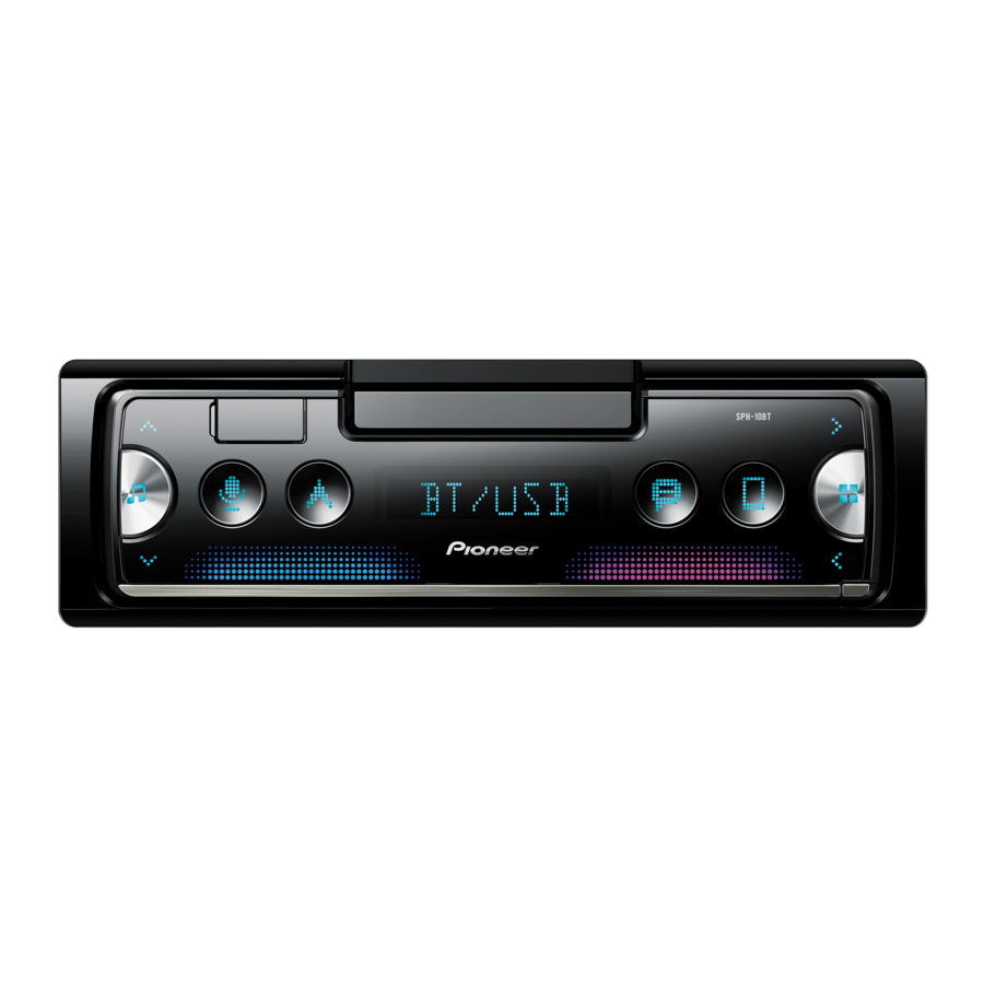
Pioneer SPH-10BT Manual
- Operation manual (35 pages) ,
- Installation manual (33 pages) ,
- System firmware update instructions (7 pages)
Advertisement
Connections

- When speaker output is used by 4 channels, use speakers over 50 W (maximum input power) and between 4 Ω to 8 Ω (impedance value). Do not use 1 Ω to 3 Ω speakers for this unit.
- When rear speaker output is used by 2 Ω of subwoofer, use speakers over 70 W (maximum input power).
* Please refer to connections for a connection method. - The black cable is ground. When installing this unit or power amp (sold separately), make sure to connect the ground wire first. Ensure that the ground wire is properly connected to metal parts of the car's body. The ground wire of the power amp and the one of this unit or any other device must be connected to the car separately with different screws. If the screw for the ground wire loosens or falls out, it could result in fire, generation of smoke or malfunction.
![]()
*1 Not supplied for this unit


When installing this unit in a vehicle without an ACC (accessory) position on the ignition switch, failure to connect the red cable to the terminal that detects operation of the ignition key may result in battery drain.

- Use this unit with a 12-volt battery and negative grounding only. Failure to do so may result in a fire or malfunction.
- To prevent a short-circuit, overheating or malfunction, be sure to follow the directions below.
- Disconnect the negative terminal of the battery before installation.
- Secure the wiring with cable clamps or adhesive tape. Wrap adhesive tape around wiring that comes into contact with metal parts to protect the wiring.
- Place all cables away from moving parts, such as the shift lever and seat rails.
- Place all cables away from hot places, such as near the heater outlet.
- Do not connect the yellow cable to the battery by passing it through the hole to the engine compartment.
- Cover any disconnected cable connectors with insulating tape.
- Do not shorten any cables.
- Never cut the insulation of the power cable of this unit in order to share the power with other devices. The current capacity of the cable is limited.
- Use a fuse of the rating prescribed.
- Never wire the negative speaker cable directly to ground.
- Never band together negative cables of multiple speakers.
- When this unit is on, control signals are sent through the blue/white cable. Connect this cable to the system remote control of an external power amp or the vehicle's auto-antenna relay control terminal (max. 300 mA 12 V DC). If the vehicle is equipped with a glass antenna, connect it to the antenna booster power supply terminal.
- Never connect the blue/white cable to the power terminal of an external power amp. Also, never connect it to the power terminal of the auto antenna. Doing so may result in battery drain or a malfunction.
- The graphical symbol
![]() placed on the product means direct current.
placed on the product means direct current.
 placed on the product means direct current.
This unit

- Power cord input
- Microphone input
- Microphone (3 m)
- Rear output or subwoofer output
- Front output
- Antenna input
- Parking sensor input
UART adaptor (supplied with parking sensor unit (ND-PS1)) can be connected (sold separately). - Fuse (10 A)
- Wired remote input
Hard-wired remote control adapter can be connected (sold separately).
Power cord
Perform these connections when not connecting a rear speaker lead to a subwoofer.

Perform these connections when using a subwoofer without the optional amplifier.

In the case of 19 above, two 4 Ω subwoofers wired in parallel will represent a 2 Ω load.
- To power cord input
- Left
- Right
- Front speaker
- Rear speaker
- White
- White/black
- Gray
- Gray/black
- Green
- Green/black
- Violet
- Violet/black
- Black (chassis ground)
Connect to a clean, paint-free metal location. - Yellow
Connect to the constant 12 V supply terminal. - Red
Connect to terminal controlled by the ignition switch (12 V DC). - Blue/white
Connect to the system control terminal of the power amp or auto-antenna relay control terminal (max. 300 mA 12 V DC). - Subwoofer (4 Ω)
- When using a subwoofer of 2 Ω, be sure to connect the subwoofer to the violet and violet/black leads of this unit. Do not connect anything to the green and green/black leads.
- Not used.
- Subwoofer (4 Ω) × 2
- Orange/white
Connect to a car's illumination signal. - Violet/white
Of the two lead wires connected to the back lamp, connect the one in which the voltage changes when the gear shift is in the REVERSE (R) position. This connection enables the unit to sense whether the car is moving forwards or backwards. - Light green
Used to detect the On/Off status of the parking brake. This lead must be connected to the power supply side of the parking brake switch.
 NOTE
NOTE
Change the initial menu of this unit. Refer to [SP-P/O] in the INITIAL settings. The subwoofer output of this unit is monaural.
Power amp (sold separately)
Perform these connections when using the optional amplifier.

- System remote control
to blue/white cable. - Power amp (sold separately)
- Connect with RCA cables (sold separately)
- To front output
- Front speaker
- To rear output or subwoofer output
- Rear speaker or subwoofer
Installation
- Check all connections and systems before final installation.
- Do not use unauthorized parts as this may cause malfunctions.
- Consult your dealer if installation requires drilling of holes or other modifications to the vehicle.
- Do not install this unit where:
- it may interfere with operation of the vehicle.
- it may cause injury to a passenger as a result of a sudden stop.
- Install this unit away from hot places such as near the heater outlet.
- Optimum performance is obtained when the unit is installed at an angle of less than 45°.
![]()
- When installing, to ensure proper heat dispersal when using this unit, make sure you leave ample space behind the rear panel and wrap any loose cables so they are not blocking the vents.
![]()
- Detach the front panel first by pressing the detach button to remove the smartphone holder.


DIN mount installation
- Insert the supplied mounting sleeve into the dashboard.
- Secure the mounting sleeve by using a screwdriver to bend the metal tabs (90°) into place.

- Dashboard
- Mounting sleeve
- Make sure that the unit is installed securely in place. An unstable installation may cause skipping or other malfunctions.

When not using the supplied mounting sleeve
- Determine the appropriate position where the holes on the bracket and the side of the unit match.
![]()
- Tighten two screws on each side.

- Screw
- Mounting bracket
- Dashboard or console
- Use either truss (5 mm × 9 mm) or flush surface (5 mm × 9 mm) screws, depending on the bracket screw holes.


Removing the unit (installed with the supplied mounting sleeve)
- Remove the trim ring.
![]()
- Trim ring
- Releasing the front panel allows easier access to the trim ring.
- When reattaching the trim ring, point the side with the dent part up.
- Trim ring
- Insert the supplied extraction keys into both sides of the unit until they click into place.
- Pull the unit out of the dashboard.
![]()


To secure the front panel
The front panel can be secured with the supplied screw.

- Screw
Installing the microphone
The microphone should be placed directly in front of the driver at a suitable distance to pick up their voice clearly.

It is extremely dangerous to allow the microphone lead to become wound around the steering column or shift lever. Be sure to install the microphone in such a way that it will not obstruct driving. It is recommended to use the clamps (sold separately) to arrange the lead.
NOTE
Depending on the vehicle model, the microphone cable length may be too short when you mount the microphone on the sun visor. In such cases, install the microphone on the steering column.
To install on the sun visor
- Fit the microphone lead into the groove.
![]()
- Microphone lead
- Groove
- Install the microphone clip on the sun visor.
Lowering the sun visor reduces the voice recognition rate.
![]()
- Microphone clip


To install on the steering column
- Slide the microphone base to detach it from the microphone clip.
![]()
- Microphone
- Microphone clip
- Microphone base
- Install the microphone on the rear side of the steering column.
![]()
- Double-sided tape


Documents / ResourcesDownload manual
Here you can download full pdf version of manual, it may contain additional safety instructions, warranty information, FCC rules, etc.
Advertisement


Need help?
Do you have a question about the SPH-10BT and is the answer not in the manual?
Questions and answers