Advertisement
Quick Links
Advertisement

Subscribe to Our Youtube Channel
Related Manuals for Qingqi BLACK SEVEN GD125


Summary of Contents for Qingqi BLACK SEVEN GD125
- Page 1 QM125-2X (BLACK SEVEN) GD125 SERVICE MANUAL...
- Page 2 This maintenance manual is meant to instruct the maintenance service personnel with competent knowledge and skills on motorcycle maintenance to inspect, adjust, repair and maintain Qingqi motorcycles. The final interpretation right of this manual belongs to our company. Without the company's prior permission, no content in this manual may be quoted or reproduced.
- Page 3 GROUP INDEX GENERAL INFORMATION PERIODIC MAINTENANCE ENGINE FUEL SYSTEMAND THROTTLE BODY EI SYSTEM DLAGNOSISEI ELECTRICAL SYSTEMEI CHASSIS SERVICING INFORMATION...
- Page 4 HOW TO USE THIS MANUAL TO LOCATE WHAT YOU ARE LOOKING FOR : The text of this manual is divided into sections. As the title of these sections are listed on the Previous page as GROUPINDEX, select the section Where you are looking for. Holding the manual as shown at the right will allow You to find the first page of the section easily.
- Page 5 SYMBOL Listed in the table below are the symbols indicating instructions and other information necessary for servicing and meaning associated with them respectively. SYMBOL DEFINITION SYMBOL DEFINITION Torque control required. Use fork oil. Data beside it indicates specified torque Apply oil. Use engine oil unless otherwise Apply THREAD LOCK.
- Page 6 ABBREVIATIONS USED IN THIS MANUAL 本手册中使用的缩写 ABDC : After Bottom Dead Center : Liquid Crystal Display : Alternating Current : Light Emitting Diode : American Petroleum Institute : LeftHand ATDC : After Top Dead Center 后 :Maximum BBDC : Before Bottom Dead Center :Minimum : Bettom Dead Center BTDC...
- Page 7 WIRE COLOR : Black : Green : Purple : Blue : Gray : Red : Light green : Brown : Shallow blue :Dark brown : Orange : White :Dark green : Pink : Yellow Black with Blue tracer Black with Brown tracer Black with Green tracer Black with Gray tracer Black with Orange tracer...
- Page 8 Light green with Red tracer Orange with Black tracer Orange with Blue tracer Orange with Green tracer Orange with Red tracer Orange with White tracer Pink with Blue tracer Pink with Green tracer PuBl Purple with Black tracer Purple with Blue tracer PuBr Purple with Brown tracer Purple with Green tracer...
- Page 9 GENERAL INFORMATION CONTENTS INFORMATIONLABELS………………………………………………………………………… 1 - 1 1 - 2 GENERALPRECAUTIONS……………………………………………………………………… EXTERIOR PHOTOGRAPH……………………………………………………………………… 1 - 3 FUNCTION OF EI SENSOR……………………………………………………………………… 1 - 4 SERIAL NUMBER LOCATION…………………………………………………………………… 1 - 5 FUEL ANDOILRECOMMENDATIONS………………………………………………………… 1 - 6 1 - 8 BREAK-INPROCEDURES……………………………………………………………………… EXTERIORILLUSTRATION……………………………………………………………………… 1 - 9 1 - 10 SPECIFICATIONS…………………………………………………………………………………...
- Page 10 GENERAL INFORMATION 1-1 INFORMATIONLABELS WARNING / CAUTION / NOTE Please read this manual and follow its instructions carefully. To emphasize special information, the symbol and the words WARNING, CAUTION and NOTE have special meanings. Pay special attention to the messages highlighted by these signal words Indicates a potential hazard that could result in death or injury.
- Page 11 ❖ Proper service and repair procedures are important for the safety of the service mechanic and the safety and reliability of the vehicle. ❖ When 2 or more persons work together, pay attention to the safety of each other.When it is necessary to run the engine indoors, make sure that exhaust gas is forced outdoors.
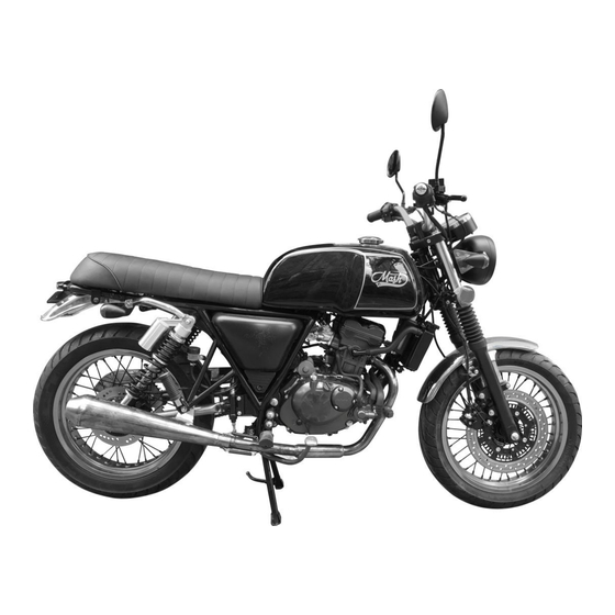
- Page 12 GENERAL INFORMATION 1-3 EXTERIOR PHOTOGRAPH N O T E Difference between photographs and actual motorcycles depends on the markets.
- Page 13 1-4 GENERAL INFORMATION FUNCTION OF EI SENSOR EI ★ECU (Engine Control Unit, EI Control Unit)ECU ECU decide the fuel injection volume and ignition time to adjust the fuel injector opening and closing rate which is considered the engine speed, intake air pressure,in take air volume,engine temperature,oxygen volume and throttle opening angle,etc.
- Page 14 GENERAL INFORMATION 一般信息 1-5 ★CLT Sensor (Engine Coolant Temperature Sensor ) CLT sensor is located on thecylinder block’s water jacket, the intake pipe or the cylinder head coolant passage’s thermostat part for contact with the coolant. CLT sensor is the NTC (Negative Temperature Coefficient) resister that measure the coolant temperature and inform ECU.
- Page 15 1-6 GENERAL INFORMATION FUEL AND OIL RECOMMENDATION FUEL ◉ Gasoline used should be graded 92 octane (Research Method) or higher. An ◉ unleaded gasoline type is recommended ENGINE OIL SPECIFICATION Grade Classification system Over SL 10W-40 If an SAE 10W-40 motor oil is not available, select an alternative according to the right chart.
- Page 16 Use a premium quality 4-stroke motor oil to ensure longer service life of your motorcycle. ❖ Dont mix the unrecommended oil.It could damage the engine. ❖ When refilling the oil tank,dont allow the dust to get inside. ❖ Mop the oil spilt. ❖...
- Page 17 GENERAL INFORMATION1-7 ANTIFREEZE ◉ Antifreeze selection: 1. Antifreeze must not be mixed using. 2.The freezing point of antifreeze is normally lower than the local minimum ambient temperature 5-10 degrees. 3. The boiling point of antifreeze is more than 107 ° C. This motorcycle engine is water cooling system.
- Page 18 1-8 GENERAL INFORMATION BREAK-IN PROCEDURES During manufacture only the best possible materials are used and all machined parts are finished to a very high standard but it is still necessary to allow the moving parts to BREAK-IN before subjecting the engine to maximum stresses.
- Page 19 一般信息 GENERAL INFORMATION1-9 EXTERIOR ILLUSTRATION 外部尺寸...
- Page 20 1-10 GENERAL INFORMATION 一般信息 SPECIFICATIONS 技术参数 ⊙ DIMENSIONS AND MASS 尺寸和质量 ITEM分类 QM125-2X Overall length总长度 2137 mm Overall width整体宽度 827 mm Overall height总高 1208 mm Wheelbase轴距 1435 mm Minimum ground clearance最小离地间隙 300 mm Turning clearance circle diameter车削间隙圆直径 5400mm Overall mass整体质量 141 kg ⊙...
- Page 21 一般信息 GENERAL INFORMATION 1-11 CHASSIS 车体 ITEM分类 QM125-2X Front suspension前减震 Spring oil damping弹簧油阻尼 Rear suspension后减震 Spring oil damping弹簧油阻尼 Steering angle转向角 39° (right & left)39°(左右) Caster脚轮 29° Front brake前制动 Disk brake盘式制动器 Rear brake后刹车 Disk brake盘式制动器 Front tire size前轮胎尺寸 110/70-17 Rear tire size后轮胎尺寸 130/70-17 ⊙ELECTRICAL 电器部分...
- Page 22 PERIODIC MAINTENANCE CONTENTS PERIODIC MAINTENANCESCHEDULE………………………………………………………… 2 - 1 PERIODIC MAINTENANCECHART……………………………………………………………… 2 - 1 LUBRICATION POINTS…………………………………………………………………………… 2 - 3 MAINTENANCEPROCEDURES………………………………………………………………… 2 - 4 VALVE CLEARANCE……………………………………………………………………………… 2 - 4 SPARKPLUG……………………………………………………………………………………… 2 - 7 EXHAUST PIPE NUTS AND MUFFLER MOUNTINGBOLTS………………………………… 2 - 8 AIRCLEANER………………………………………………………………………………………...
- Page 23 PERIODIC MAINTENANCE 2-1 PERIODIC MAINTENANCE SCHEDUL The chart below lists the recommended intervals for all the required periodic service work necessary to keep the motorcycle operating at peak performance and economy. More frequent servicing should be performed on motorcycles that are used under severe conditions.
- Page 24 2-2 PERIODIC MAINTENANCE CHASSIS ◉ Interval Item Initial 1,000 km Every 4,000 km Every 8,000 km Drive chain Clean and lubricate every 1,000km Brake Inspect Inspect ─ ─ Inspect Inspect Brake hose Replace every 4 years Inspect Inspect ─ Brake fluid Replace every 2 years Tires Inspect...
- Page 25 PERIODIC MAINTENANCE 2-3 LUBRICATION POINT Proper lubrication is important for smooth operation and long life of each working part of the motorcycle. Major lubrication points are indicated below. O- Motor oil, G– Grease Clutch lever holder Passenger footrests pivot ① ②...
- Page 26 2-4 PERIODIC MAINTENANCE MAINTENANCE PROCEDURE This section describes the service procedure for VALVE each section of the periodic maintenance. CLEARANCE N O T E Inspect Initial 1,000 km and Every 4,000 km 注意 The clearance specification is for COLD state. The valve clearance specification is different for intake and exhaust valves.
- Page 27 PERIODIC MAINTENANCE 2-5 Rotate the magneto rotor to set the front cylinder’s piston at TDC (Top Dead Center) of the compression stroke. (Rotatetherotoruntil“T”lineontherotorisaligned with the center of hole on the crankcase.) To inspect the front cylinder’s valve clearance, insert the thickness gauge to the clearance between the camshaft and the tappet Valve clearance (when cold)
- Page 28 2-6 PERIODIC MAINTENANCE In case that valve adjustment which there is no the tappet shim selection chart, please follow instructions of example in the below. For example, the intake clearance is 0.4 and the shim is170(1.70mm),select195(1.95mm)of the shim which170(1.70mm)of the shim add up the excess clearance 0.25 mm when adjust with the standard 0.15 as the intake standard clearance 0.1-0.2 mm.
- Page 29 PERIODIC MAINTENANCE 2-7 SPARK PLUG N O T E Clean Initial 1,000 km and Every 4,000 km, Replace Every 8,000 km. Disconnect the spark plug caps. Remove the spark plugs. SPARK PLUG TYPE SPECIFICATION Hot type CR7E Standard type CR8E Cold type CR9E...
- Page 30 2-8 PERIODIC MAINTENANCE EXHAUSE PIPE NUTS AND MUFFLER MOUNTING BOLTS N O T E Tighten Initial 1,000 km and Every 4,000 km. Tighten the exhaust pipe nuts ①, and muffler mounting bolts ②to the specified torque. Exhaust pipe nut 11N∙m (1.1kg∙m) Muffler mounting bolt :16.5N∙m (1.65kg∙m)
- Page 31 PERIODIC MAINTENANCE 2-9 AIR CLEANER N O T E Clean Every 3,000 km, Replace Every 12,000 km. ● With the hook ①、②、③removed, remove the left side cover. Remove the four air cleaner inlet cap mounting bolts ④, and then remove the air cleaner inlet cap ⑤.
- Page 32 FUEL HOSE燃油软管 N O T E Inspect Initial 1,000 km and Every 4,000 km, Replace every 4 years. Remove the left frame cover. (Refer to page 5-2) Inspect the fuel hoses for damage and fuel leakage. If any defects are found, the fuel hoses must be replaced.
- Page 33 定期保养 PERIODIC MAINTENANCE 2-11 CLUTCH N O T E Inspect Initial 1,000 km and Every 4,000 km Clutch play should be 4 mm as measured at the clutch lever holder before the clutch begins to disengage. If the play in the clutch is incorrect, adjust it in the following way: Loosen the lock nut ①...
- Page 34 2-12 PERIODIC MAINTENANCE ENGINE OIL Oil quality is a major contributor to your engine’s performance and life. Always select good quality engine oil. ● Don’t mix the unrecommended oil. It could damage the engine. ● When refilling the oil, don’t allow the dust ⊙ENGINE OIL SPECIFICATION to get inside.
- Page 35 PERIODIC MAINTENANCE 2-13 ⊙ENGINE OIL LEVEL CHECK Follow the procedure below to inspect the engine oil level. Start up the engine and allow it to run for several minutes at idling speed. Turn off the engine and wait about three minutes, then check the oil level through the inspection window.
- Page 36 2-14 PERIODIC MAINTENANCE Necessarily, confirm and clean the oil strainer when replace Engine Operating the motorcycle with an incorrect (specially, when first replacement). amount of engine oil can damage your motorcycle. Too little or too much engine oil can damage your engine.
- Page 37 PERIODIC MAINTENANCE 2-15 ⊙ENGINEOILANDFILTERCHANGE More frequent servicing may be performed on motorcycles that are used under severe conditions, inspect ①Quantity of Engine oil, ②Pollution degree of Engine oil before riding the motorcycle and then supplement and replace at any time to prevent damage of the engine.
- Page 38 2-16 PERIODIC MAINTENANCE Hold the motorcycle vertically using the center stand. N O T E Place the motorcycle on firm and flat ground. Place a drain pan under the engine. Remove the engine oil filler plug①. Drain the engine oil by removing the engine oil drain plug ②...
- Page 39 定期保养 PERIODIC MAINTENANCE 2-17 New and used oil can be hazardous. Children and pets may be harmed by swallowing new or used oil. Continuous contact with used engine oil has been found to cause skin cancer in laboratory animals. Brief contact with used oil may irritate skin.
- Page 40 2-18 PERIODIC MAINTENANCE Tighten the drain plug ② to the specified torque. At this time, insert the gasket necessarily. Approximately 850 mlof the engine oil must Oil drain plug : 28N∙m (2.8kg∙m) be required when changing the engine oil only without replacing the engine oil filter.在 只更换机油时,大约需要...
- Page 41 PERIODIC MAINTENANCE 2-19 Install the engine oil filler plug①. Start the engine and allow it idle for a few minutes. Check the oil drain plug ② to ensure that there is no oil leakage. Check the engine oil level according to Engine Oil Level Check procedure.
- Page 42 PERIODIC MAINTENANCE 2-20 ANTIFREEZE This motorcycle engine is water cooling system. During motorcycle running, the antifreeze is high temperature and high pressure in the cooling system. So, it is strictly forbidden opening the radiator cap in this state, avoiding burn.The antifreeze must be added in a timely manner and sufficient amount to prevent damaging the engine.
- Page 43 2-21 PERIODIC MAINTENANCE Antifreeze replacement Carry out this work on about 10000 km running or when using the motorcycle for a year. The operation is following: Please stand the motorcycle on a level ground with stand, take a container and put under the draining bolt③, then remove the bolt③, so antifreeze is outflow.
- Page 44 PERIODIC MAINTENANCE 2-22 Common fault of cooling system Tighten the radiator cover, start the engine, Check the makeup water tank, radiator, fan, repeated acceleration and deceleration of the water pump, rubber water pipe and antifreeze. If engine in place until the fan of cooling system antifreeze boiling occurs during vehicle traveling, please find the reason: turned on (or the needle of water temperature...
- Page 45 2-23 PERIODIC MAINTENANCE DRIVE CHAIN N O T E Clean and Lubricate Every 1,000 km. Visually check the drive chain for the possible defects listed below. (Support the motorcycle by the jack or block, turn the rear wheel slowly by hand with the trans- mission shifted to Neutral.) ●...
- Page 46 PERIODIC MAINTENANCE 2-24 ● Count out 21 pins (20 pitches) on the chain and mea- sure the distance between the two points. If the distance exceeds the service limit, the chain must be replaced. Service limit Drive chain 20-pitch length 259.0 mm ●...
- Page 47 2-25 PERIODIC MAINTENANCE ● Wash the drive chain with kerosine. If the drive chain tends to rust quickly, the intervals must be shortened. ● After washing and drying the chain, oil it with a engine oil. The standard drive chain is a 428UO recommends that this standard drive chain should be used for the replacement.
- Page 48 PERIODIC MAINTENANCE 2-26 BRAKE SYSTEM ⊙BRAKE FLUID N O T E Be sure to check the brake fluid level in the master [ BRAKE] cylinder. If the level was found to be lower than the Inspect Initial 1,000 km and Every 4,000 km. lower mark holding the motorcycle upright, inspect [ BRAKE HOSE &...
- Page 49 2-27 PERIODIC MAINTENANCE As the brake pads wear, the fluid level will drop to ⊙BRAKE PADS compensate for the new position of brake pads.Replenishing the master cylinder to considered normal periodic maintenance. Inspect the front and rear brake pads to determine whether or not the friction pads are worn down to the grooved limit line.
- Page 50 PERIODIC MAINTENANCE 2-28 The front and rear brake system requires the brake hose or the brake fluid to be replaced according to periodic inspection chart by your authorized dealer for safety as they operate at high pressure. Riding with worn brake pads will reduce braking performance and will increase your chance of having accident.
- Page 51 2-29 PERIODIC MAINTENANCE BRAKE DISK INSPECTION ◉ Check the brake disk for damage or cracks. FRONTBRAKE BRAKE FLUID LEVELCHECK Keep the motorcycle upright and place the handle bars straight. Check the brake fluid level by observing the lower ...
- Page 52 PERIODIC MAINTENANCE 2-30 FRONT BRAKE FLUIDREPLACEMENT ◉ Place the motorcycle on a level surface and keep the handlebars straight. Remove the master cylinder reservoir cap and diaphragm. Suck up the old brake fluid as much as possible. Fill the reservoir with new brake fluid.
- Page 53 2-31 PERIODIC MAINTENANCE AIRBLEEDINGOFTHEBRAKEFLUID ◉ CIRCUIT Air trapped in the brake fluid circuit acts like a cushion to absorb a large proportion of the pressure developed by the master cylinder and thus interferes with the full braking performance of the brake caliper.
- Page 54 N O T E While bleeding the brake system, replenish the brake fluid in the reservoir as necessary. Make sure that there is always some fluid visible in the reservoir. Close the air bleeder valve, and disconnect the hose. Fill the reservoir with brake fluid to the upper line.
- Page 55 BRAKE LAMP SWITCH ◉ Adjust the front and rear brake light switches so that when the front brake handle is clenched or the brake pedal is pressed, the brake light will light up before the pressure is felt. Front brake lamp switch Rear brake lamp switch...
- Page 56 PERIODIC MAINTENANCE 2-34 STEERING N O T E Inspect Initial 1,000 km and Every 4,000 km.。 Steering should be adjusted properly for smooth turning of handlebars and safe running. Overtight steering pre- vents smooth turning of the handlebars and too loose steering will cause poor stability.
- Page 57 REAR SUSPENSION N O T E Inspect Every 4,000 km. Inspect the rear shock absorber for oil leakage and mounting rubbers including engine mounting for wear and damage. Replace any defective parts, if necessary.
- Page 58 PERIODIC MAINTENANCE 2-36 TIRE N O T E Inspect Initial 1,000 km and Every 4,000 km. Inspect the tire pressure and the tire thread depth periodically. Inspect frequently the tire pressure for the safety and the tire life. Failure to follow the sewarnings may result in an accident due to tire failure.
- Page 59 2-37 PERIODIC MAINTENANCE The standard tire on QM125-2X ( B7 ) is 110/70-17or front and 130/70-17 for rear. The use of tires other than those specified cause instability. highly recommended to use GenuineTire. TIREPRESSURE ◉ Insufficient airpressureinthetires not only hasten tire wear but also seriouslyaffectsthestabilityofthe motorcycle.
- Page 60 PERIODIC MAINTENANCE 2-38 CRACKS AND CUT CHASSIS BOLTS AND NUTS N O T E Check if There are visible cracks and cuts.There are Tighten Initial 1,000 km and Every 4,000 km. abnormal wears. Check that all chassis bolts and nuts are tightened to their specified torque.
- Page 61 2-39 PERIODIC MAINTENANCE ◉ COMPRESSION TESTPROCEDURE N O T E Before testing the engine for compression pres- sure, make sure that the cylinder head bolts are tightened to the specified torque values and valves are properly adjusted. Have the engine warmed up by idling before testing.
- Page 62 PERIODIC MAINTENANCE 2-40 OIL PRESSURE Check the oil pressure periodically. This will give a good indication of the condition of the moving parts. Standard Oil pressure油压 1.4± 0.2 kg/cm (at 60 ℃∙4,000 rpm) If the oil pressure is lower or higher than the specification, the following causes may be considered.
- Page 63 ENGINE CONTENT INTRODUCTION……………………………………………………………………………………… ENGINE DISASSEMBLY……………………………………………...…………………… INSPECTION AND MAINTENANCE OF ENGINE COMPONENTS……………………………………………………………….…………… 3-19...
- Page 64 3-1 ENGINE INTRODUCTION The engine is separated from the vehicle: Remove the saddle, fuel tank (oil pipe, air pipe, power connector), and remove the guard; Remove the oil and engine coolant, remove the radiator; Disassemble the drive chain, disassemble the battery cable, magneto cable and other connectors, and the gear display switch connector;Remove the shift lever and left front footrest;...
- Page 65 ENGINE 3-2 The engine is separated from the vehicle: Remove the frame cover and fuel tank guard ● Remove the saddle assembly fixing bolts and remove the saddle①. ● Remove the fuel tank ②. (Refer to page 5-2) Remove the frame cover correctly After removing the hooks ③, 、...
- Page 66 3-3 ENGINE Drain the oil and the coolant; • Remove the oil drain plug and drain the engine oil. Engine oil: SAE10W-40 ENGINE OIL CAPACITY Oil change 850ml Oil and filter change 950ml Engine overhaul 1,400ml • Remove the exhaust pipe,remove the thermostat water pipe, remove the lower water pipe;...
- Page 67 ENGINE 3-4 Remove the small sprocket; Remove the two tightening screw and one axle bolt. 。 • Remove the chain wheel. • Remove the idle speed control conducting wire④. Remove the ground conducting wire • ⑤ Remove the gear display switch⑥. •...
- Page 68 3-5 ENGINE • Remove theclutch cable ① • Remove the throttle body ② • Remove the engine fastening bolts④, ⑤、⑥. • Take off the engine.
- Page 69 ENGINE 3-6 Engine decomposition ● Take off the bolts of cylinder head cover①. NOTE Beat the cylinder head cover with a rubber hammer. ● Remove the plug②. ● Remove the plug③. ● Rotate the magneto rotor to set the front cylinder’s piston at TDC (Top Dead Center) of the compression stroke.
- Page 70 3-7 ENGINE ● Remove the chain guide Ⅱ①. ● Remove the head ass’y,cylinder②. ● Loosen the chain tensioner③. ● Remove the camshaft comp,intake④ and camshaft comp,exhaust⑤. NOTE Be careful that the chain falls into the crankcase. ● Remove the cylinder head. NOTE Beat the cylinder with the rubber hammer.
- Page 71 ENGINE3-8 ● Remove the cylinder block. ● Remove thecirclip,piston pin②. ● Remove the pin,piston①. ● Take off the piston③. ● Remove the cap④ and filter comp,engine oil. ● Remove the water pump tee⑤. ● Remove the cover comp,clutch. ● Remove the cover,starter idle gear⑥.
- Page 72 3-9 ENGINE ● Remove themotor assy, starting①. ● Remove the gear②. ● Remove the switch assy,gear shift③. ● Remove the cover,magneto④.
- Page 73 ENGINE3-10 ● Remove thecontact,gearshif switch①and spring,gear shift switch contact②. ● Remove thecover comp,clutch③. ● Remove the five clutch pressure plate bolts. ● Remove the disk,clutch pressure④.
- Page 74 3-11 ENGINE ● Remove the plate,clutch drive and plate, clutch driven①. ● Remove the clutch compression nut ②, and remove the clutch spline sleeve ③. ● Remove thegear assy,primary driven④. ● Remove the primary driving gear and drive gear of oil pump⑤. ●...
- Page 75 ENGINE3-12 ● Remove the shift shaft assembly ①. ● Remove the oil pump assembly ②. NOTE Be careful that the oil pump couldn’t be separated. ● Remove the two bolts of the cam baffle, and remove the cam baffle ③. ●...
- Page 76 3-13 ENGINE ● Remove themagnetomotor rotor②. 拆 ● Remove the start the driven gear③. ● Fix the unpacking machine④ as the picture. ● Remove the left box.
- Page 77 ENGINE3-14 ● Remove the cam comp,gear shift①.Remove the fork,gear shift NO.1 and shaft,gear shift fork NO.1② . ● Remove the fork,gear shift NO.3 and shaft,gear shift fork NO.2 ● Remove the shaft comp,counter Remove the shaft comp,drive ● Remove the shaft comp,crank balancer⑥.Remove the crankshaft assy 。...
- Page 78 3-15 ENGINE Cylinder head combination decomposition • See if the valve room is carbon-accumulating. Twointake valve, slightly larger diameter.Twoexhaust valve, slightly smaller in diameter. • Remove the four valve lifters③ and adjusting shims④, and pay attention to their installation positions, do not mix them during assembly.
- Page 79 ENGINE3-16 • Pressurized gas door lock disassembly device, remove the lock plate, remove the valve base, valve oil seal The same removal method for the intake and exhaust valves. Valve lock plate①. Valve retainer②. Valve spring ③. Valve oil seal④. Valve spring seat⑤.
- Page 80 3-17 ENGINE When the piston ring is installed, 3 ring openings are staggered 120° respectively. NOTE When installing the piston, the top notch portion corresponds to the valve and the arrow markings on the piston face the exhaust valve. NOTE Note When replacing: A gas ring chrome plating①.
- Page 81 ENGINE3-18 Engine assemble Considerations 1. Reverse operation in the above order. 2. The disassembled engine must be cleaned clean. When the left and right box is merged, apply the sealant evenly and the fixing bolt diagonally according to the torque requirement to lock. When installing the piston, apply lubricating oil.
- Page 82 3-19 ENGINE ENGINE COMPONENT INSPEC TION AND SERVICE Be sure to identify each removed part as to its location, and lay the parts out in groups designatedas “cylinder”, “Exhaust”, “Intake”, so that each will be restored to the original location during assembly.
- Page 83 ENGINE 3-20 VALVE STEM RUNOUT Check the valve stem for abnormal wear or bend. Place the valve on V-blocks and measure run out. If the service limit is exceeded or abnormal condition exists, replace the valve. Service limit Valve stem runout 0.05 mm Dial gauge : Magnetic stand :...
- Page 84 3-21 ENGINE VALVE GUIDE-VALVE STEM CLEAR- ANCE Measure the clearance in the valve guide-valve stem, by rigging up the dial gauge. If the clearance is measured exceeds the limit specified below, then deter- mine whether the valve or the guide should be replaced to reduce the clearance to within the standard range: 如图所...
- Page 85 ENGINE 3-22 VALVE SPRING The force of the coil spring keeps the valve seat tight. A weakened spring results in reduced engine power out- put and often accounts for the chattering noise coming from the valve mechanism. Check the valve springs for proper strength by measuring their free length and also by the force required to compress them.
- Page 86 3-23ENGINE CYLINDER DISTORTION Check the gasketed surface of the cylinder for distortion with a straightedge and thickness gauge, taking a clearance reading at several places as indicated. If the largest reading at any position of the straightedge exceeds the limit, replace the cylinder.
- Page 87 ENGINE 3-24 CAM CHAIN TENSIONER Check the contacting surface of the cam chain tensioner. If it is worn or damaged, replace it with a new one. CAM CHAIN AND CAM CHAIN GUIDE Check the cam chain for wear, damage and kinked or binding links.
- Page 88 3-25 ENGINE PISTON DIAMETER INSPECTION Measure the outside diameter of piston in the direction perpendicular to the piston pin axis at the height from the skirt as shown in the illustration using a micrometer.If the measurement is found less than the service limit, replace the piston.
- Page 89 ENGINE 3-26 PISTON PIN DIAMETER INSPECTION Using a micrometer, measure the piston pin outside diameter at three position, both the ends and the center. If any of the measurements is founds less than the ser- vice limit, replace the pin.
- Page 90 3-27 ENGINE PISTON RING-TO-GROOVE CLEAR ANCE INSPECTION Remove carbon deposit both from the piston ring and its groove. Fit the piston ring into the groove. With the ring com- pressed and lifted up, measure the clearance on the bottom side of the ring using a thickness gauge.
- Page 91 ENGINE3-28 CONROD SMALL END INSIDE DIAMETER INSPECTION Using a dial calipers, measure the conrod small end inside diameter both in vertical and horizontal directions. If any of the measurements exceeds the service limit, replace the conrod. Standard Service limit Conrod small end 13.006~13.014 13.040 mm...
- Page 92 3-29 ENGINE CRANKSHAFT REASSEBLY Measure the width between the webs referring to the figure below when rebuilding the crankshaft. Standard Width between webs 72±0.1 mm MAGNETO ASSY DISASSEMBLY Remove the stator. STARTER CLUTCH Install the starter driven gear onto the starter clutch and turn the starter driven gear by hand(the gear turns in only one direction).
- Page 93 ENGINE 3-30 REASSEMBLY Apply a small quantity of THREAD LOCK “1324”to the starter clutch bolts and tighten them to the specified torque while holding the rotor holder. Thread Lock “1324” Rotor holder:09930-44510 Starter clutch bolt 23~28N∙m(2.3~2.8kg∙m) STARTER DRIVEN GEAR ...
- Page 94 3-31ENGINE CLUTCH DRIVE PLATES Measure the thickness and claw width of the clutch drive plates using vernier calipers. If a clutch drive plate is not within the service limit, replace the clutch plates as a set. Standard Service limit Clutch drive plate 2.9~3.1 mm 2.6 mm...
- Page 95 ENGINE 3-32 CLUTCH SPRING FREE LENGTH Measure the free length of each clutch spring using vernier calipers. If any spring is not within the service limit, replace all of the spring. Service limit Clutch spring 34.3mm free length Vernier calipers :09900-20101 ...
- Page 96 ENGINE 3-33 OIL PUMP Turn the oil pump shaft and check that rotation is smooth. If any abnormal condition is found, replace the oil pump with new one. GEARSHIFT SHAFT Disassemble and reassemble the gearshift shaft as shown in right picture. TRANSMISSION ...
- Page 97 ENGINE 3-34 Thickness gauge : 09900-20806 Vernier calipers:09900-20101 Shift fork groove width Standard NO.1 & NO.2 5.0~5.1 mm NO.3 5.0~5.1mm Shift fork thickness Standard NO.1 & NO.2 4.8~4.9 mm NO.3 4.8~4.9 mm CRANKCASE BEARING INSPECTION Rotate the bearing inner race by finger to inspect for abnormal play, noise and smooth rotation while the bearings are in the crankcase.Replace the bearing in the following procedure if there is...
- Page 98 3-35ENGINE DISASSEMBLY RIGHT CRANKCASE BEARING Remove the bearing retainer. Remove the bearings ①②③and ④. Bearing remover17 mm) : 09923-73210 Bearing remover(20~35 mm) :09923-74510 Bearing installer:09913-76010 Theremovedbearingshouldbereplacewithanew one. LEFT CRANKCASE BEARING Remove the oil seals⑤and⑥. Oil seal remover :09913-50121...
- Page 99 ENGINE 3-36 Remove the bearing retainer. Remove the bearings ①②③and④. Bearing remover(17 mm) : 09923-73210 Bearing remover(20~35 mm) :09923-74510...
- Page 100 EI SYSTEM DIAGNOSIS CONTENTS PRECAUTIONS IN SERVICING……………………………………………………………………………………………………………… [4-1] EI SYSTEM TECHNICAL FEATURES ……………………………………………………………………………………………………… [4-5] SELF-DIAGNOSIS FUNCTION………………………………………………………………………………………………………………[4-10] EI SYSTEM TROUBLE SHOOTING…………………………………………………………………………………………………………[4-11] CUSTOMER COMPLAINT ANALYSIS ………………………………………………………………………………………………[4-11] SELF-DIAGNOSTIC PROCEDURES ……………………………………………………………………………………………………[4-13] SELF-DIAGNOSIS RESET PROCEDU………………………………………………………………………………………………… [4-13] MALFUNCTION CODE AND DEFECTIVE CONDITION………………………………………………………………………[4-14] “P0031”,“P0032” OXYGEN SENSOR HEATER CIRCUIT MALFUNCTION &“P0131”,“P0132” OXYGEN SENSOR CIRCUIT MALFUNCTION……………………………………………………………………………………[4-19] “P0107”or“P0108”MAP&IAT (Pressure function)SENSOR CIRCUIT MALFUNCTION…………………………...
- Page 101 4-1 EI SYSTEM DIAGNOSIS PRECAUTIONS IN SERVICING When handling the component parts or servicing the EI system, observe the following points for the safety of the system. ⊙ELECTRICAL PARTS ▣ CONNECTOR / COUPLER • When connecting a connector, be sure to push it in until a click is felt.
- Page 102 EI SYSTEM DIAGNOSIS 4-2 • When connecting meter probe from the terminal side of the coupler (connection from harness side not being possible), use extra care not to force and cause the male terminal to bend or the female terminal to open. Connect the probe as shown to avoid opening of female terminal.
- Page 103 4-3 EI SYSTEM DIAGNOSIS • When disconnecting and connecting the ECU, make sure to turn “OFF” the ignition switch, or electronic parts may get damaged. • Battery connection in reverse polarity is strictly INCORRECT prohibited. Such a wrong connection will damage the components of the EI system instantly when reverse power is applied.
- Page 104 EI SYSTEM DIAGNOSIS 4-4 • Never connect an ohmmeter to the ECU with its coupler connected. If attempted, damage to ECU or sensors may result. • Be sure to use a specified voltmeter / ohmmeter. Otherwise, accurate measurements may not be obtained and personal injury may result.
- Page 105 4-5 EI SYSTEM DIAGNOSIS EI SYSTEM TECHNICAL FEATURES EI SYSTEM’S CONTROL DIAGRAM MAP&IAT Sensor (Temperature function) FUEL TANK AIR CLEANER ISC Solenoid TP Sensor FUEL PUMP THROTTLE BODY MAP&IAT Sensor (Pressure function) INTAKE PIPE FUEL INJECTOR WT Sensor CYLINDER CKP Sensor Sensor EXHAUST PIPE : Electrical signal flow...
- Page 106 EI SYSTEM DIAGNOSIS 4-6 ⊙ INJECTION TIME (INJECTION VOLUME) The factors to determine the injection time include the basic fuel injection time, which is calculated on the basis of intake air pressure, engine speed and throttle opening angle, and various compensations. These compensations are determined according to the signals from various sensors that detect the engine and driving conditions.
- Page 107 4-7 EI SYSTEM DIAGNOSIS ⊙ COMPENSATION OF INJECTION TIME (VOLUME) The following different signals are output from the respective sensors for compensation of the fuel injection time (volume). SIGNAL DESCRIPTION WATER COOLANT TEMPERATURE When engine temperature is low, injection time (volume) is increased.
- Page 108 EI SYSTEM DIAGNOSIS 4-8 ⊙EI SYSTEM PARTS LOCATION ① Speedometer ② Fuel injector ③ TP-TMAP SENSOR ④ CKP SENSOR ⑤ WT switch ⑥ GP sensor ⑦ CLT sensor ⑧ ISC solenoid ⑨ RO switch...
- Page 109 4-9 EI SYSTEM DIAGNOSIS ⑩Regulator ⑪Oxygen sensor ⑫Fuel pump relay...
- Page 110 EI SYSTEM DIAGNOSIS 4-10 SELF-DIAGNOSIS FUNCTION The self-diagnosis function is incorporated in the ECU. The user can only be notified by the engine warning lamp “ ” The engine warning lamp “ ” comes on when the ignition switch is set to“ON”position with the engine is stopped.
- Page 111 4-11 EI SYSTEM DIAGNOSIS EI SYSTEM TROUBLESHOOTING CUSTOMER COMPLAINT ANALYSIS Record details of the problem (failure, complaint) and how it occurred as described by the customer. For this purpose, use of such an inspection form will facilitate collecting information to the point required for proper analysis and diagnosis.
- Page 112 EI SYSTEM DIAGNOSIS 4-12 MOTORCYCLE / ENVIRONMENTAL CONDITION WHEN PROBLEM OCCURS Environmental condition 口 Fair 口 Cloudy 口 Rain 口 Snow 口 Always 口 Other Weather Temperature 口 Hot 口 Warm 口 Cool 口 Cold ( °C) 口 Always °F / Frequency 口...
- Page 113 4-13 EI SYSTEM DIAGNOSIS SELF-DIAGNOSTIC PROCEDURES Don’t disconnect couplers from ECU, battery cable from battery, ECU ground wire harness from engine or main fuse before confirming malfunction code (self-diagnostic trouble code) stored in memory. To check malfunction code, read SELF-DIAGNOSIS FUNCTION carefully to have good understanding as to how to use it. Be sure to read “PRECAUTIONS for Electrical Circuit Service”...
- Page 114 EI SYSTEM DIAGNOSIS 4-14 MALFUNCTION CODE AND DEFECTIVE CONDITION DETECTED FAILURE CONDITION MALFUNCTION DETECTED ITEM CODE CHECK FOR After engine running, if oxygen sensor heater signal open or is happened the ground short fault for 1 second by 10 times in 12 Low Voltage times test cycle, the code P0031 is indicated.
- Page 115 4-15 EI SYSTEM DIAGNOSIS DETECTED FAILURE CONDITION MALFUNCTION DETECTED ITEM CODE CHECK FOR Vehicle soak time > 240min,engine is running, during the period of the accumulated air mass is more than 2000g, if the P0111 Stuck ΔIAT is lower than 2 ℃, P0111 is indicated. TP-TMAP Intake air temperature sensor, lead wire / coupler connection.
- Page 116 EI SYSTEM DIAGNOSIS 4-16 DETECTED FAILURE CONDITION MALFUNCTION DETECTED ITEM CODE CHECK FOR After engine running, the oxygen sensor signal is inputted in ECU since then 300 sec. In this case,the sensor voltage should be the following. P0131 Low Voltage 30 mV ≤...
- Page 117 4-17 EI SYSTEM DIAGNOSIS DETECTED FAILURE CONDITION MALFUNCTION DETECTED CODE CHECK FOR ITEM After engine running, if the magneto rotor tooth’s error is happenedcontinuouslyby10timesin100timestestcycle,the code Noisy P0336 is indicated. P0336 Signal CKP Sensor wiring and mechanical parts.(CKP Sensor lead wire coupler connection) After engine running, if the CKP Sensor signal does not reach ECU for more than 0.5 sec., the code P0335 is indicated.
- Page 118 EI SYSTEM DIAGNOSIS 4-18 DETECTED FAILURE CONDITION MALFUNCTIO DETECTED N CODE CHECK FOR ITEM After engine running, if the misfire incident is larger than emission damage set threshold detected at the current test cycle of 400 engine cycles, the misfire incident count will be increase 1, after 20 P0300 count of total misfire incident, P0300 is indicated.
- Page 119 4-19 EI SYSTEM DIAGNOSIS “P0031”, or “P0032” OXYGEN SENSOR HEATER CIRCUIT MALFUNCTION & “0131”, or “0132” OXYGEN SENSOR CIRCUIT MALFUNCTION POSSIBLE CAUSE ● DETECTED CONDITION ● Oxygen sensor, Oxygen sensor heater circuit open or short. To read the flash code,with the EFI diagnostic ●...
- Page 120 EI SYSTEM DIAGNOSIS 4-20 ▣ INSPECTION 1) The connectors of oxygen sensor is located under the fuel tank, Turn the ignition switch to the “OFF” position. 2) Check the Oxygen sensor coupler for loose or poor contacts. Is OK? ● B/Bl , G/Bl (O Sensor)wire open or shorted...
- Page 121 4-21 EI SYSTEM DIAGNOSIS “ P0107” or “P0108 TP-TMAP(Pressure function)SENSOR CIRCUIT MALFUNCTION DETECTED CONDITION POSSIBLE CAUSE ● Clogged vacuum passage between throttle body ☞ To read the flash code,with the EFI diagnostic TP-TMAP (Pressure function) sensor. instrument ● Air being drawn from vacuum passage between NOTE : TP-TMAP throttle body and...
- Page 122 EI SYSTEM DIAGNOSIS 4-22 Is the input voltage OK? Go to Step 2. ● Loose or poor contactson the ECU coupler. ● Open or short circuit in the O/B wire or G/Bl wire. ◈ Step 2 TP-TMAP (Pressure function)sensor coupler①. 1) Connect the 2) Insert the needle pointed probes to the lead wire coupler.
- Page 123 4-23 EI SYSTEM DIAGNOSIS “P0112” or “P0113” TP-TMAP(Temperature function)SENSOR CIRCUIT MALFUNCTION POSSIBLE CAUSE DETECTED CONDITION TP-TMAP ● (Temperature function)sensor circuit open or short. ☞ To read the flash code,with the EFI diagnostic TP-TMAP ● (Temperature function)sensor instrument malfunction. ● ECU malfunction. ▣...
- Page 124 EI SYSTEM DIAGNOSIS 4-24 TP-TMAP (Temperature function) Sensor resistance Intake Air Temp. Resistance -20 ℃ (-40 ℉ ) ㏀ Approx 115.993 -0 ℃ (32 ℉ ) ㏀ Approx 35.629 20 ℃ (68 ℉ ) ㏀ Approx 12.688 40 ℃ (104 ℉ ) ㏀...
- Page 125 4-25 EI SYSTEM DIAGNOSIS “P0117” or “P0118” CLT SENSOR CIRCUIT MALFUNCTION DETECTED CONDITION POSSIBLE CAUSE ● CLT sensor circuit open or short. ☞ To read the flash code,with the EFI diagnostic ● CLT sensor malfunction. instrument ● ECU malfunction. ▣ INSPECTION 1) Turn the ignition switch to the “OFF”...
- Page 126 EI SYSTEM DIAGNOSIS 4-26 CLT sensor resistance Engine Coolant Resistance (To ECU) Temp. ㏀ -40 ℃ (-40 ℉ ) Approx. 48.140 ㏀ 0 ℃ (32 ℉ ) Approx.5.790 ㏀ 20 ℃ (68 ℉ ) Approx. 2.450 ㏀ 40 ℃ (104 ℉ ) Approx.
- Page 127 4-27 EI SYSTEM DIAGNOSIS “P0122” or “P0123” TP-TMAP(TPS)CIRCUIT MALFUNCTION DETECTED CONDITION POSSIBLE CAUSE ● TP sensor circuit open or short. ● TP sensor malfunction. ☞ To read the flash code,with the EFI diagnostic ● ECU malfunction. instrument ▣ INSPECTION ◈ Step 1 1) Turn the ignition switch to the “OFF”...
- Page 128 EI SYSTEM DIAGNOSIS 4-28 ◈ Step 2 1) Turn the ignition switch to the “OFF” position. 2) Disconnect the TP sensor coupler. 3) Check the continuity between (Gr/Bl) and ground. ○ ∞ Ω (Infinity) TP sensor continuity (A- Ground) Tester knob indication : Resistance (㏀) Is the continuity OK? Go to Step3 Replace the TP sensor with a...
- Page 129 4-29 EI SYSTEM DIAGNOSIS Is the voltage OK? ● O/B, Gr/Bl or G/Bl wire open or shorted to ground, or poor B16(J2-16) ,B12(J2-12) or B10(J2-10) connection of ECU coupler. ● If wire and connection are OK, intermittent trouble or faulty ECU.
- Page 130 EI SYSTEM DIAGNOSIS 4-30 “P0201”or “P0262” FUEL INJECTOR CIRCUIT MALFUNCTION DETECTED CONDITION POSSIBLE CAUSE ● Injector circuit open or short. ● Injector malfunction. ☞ To read the flash code,with the EFI diagnostic ● ECU malfunction. instrument ▣ INSPECTION ◈ Step 1 1) Remove the fuel tank.
- Page 131 4-31 EI SYSTEM DIAGNOSIS ◈ Step 2 1) Turn the ignition switch to the “ON”position. 2) Measure the injector voltage between B/G wire and ground. Battery voltage Injector voltage ⊕ ⊖ B/G- Ground, Tester knob indication: Voltage (—) NOTE Injector voltage can be detected only 3 seconds after ignition switch is turned “ON”...
- Page 132 EI SYSTEM DIAGNOSIS 4-32 “P0231” or “P0232” FUEL PUMP RELAY CIRCUIT MALFUNCTION DETECTED CONDITION POSSIBLE CAUSE ● Fuel pump relay circuit open or short. ☞ To read the flash code,with the EFI diagnostic ● Fuel pump relay malfunction. instrument ● ECU malfunction. ▣...
- Page 133 4-33 EI SYSTEM DIAGNOSIS “P0336” or “P0337” , “P1693”or“P1694” CKP SENSOR CIRCUIT MALFUNCTION DETECTED CONDITION POSSIBLE CAUSE ● Metal particles or foreign materiel being attached on the CKP and rotortip. ☞ To read the flash code,with the EFI diagnostic ● CKP circuit open or short. instrument ●...
- Page 134 EI SYSTEM DIAGNOSIS 4-34 Are the resistance and continuity OK? ● Bl/W or G/W wire open or shorted to ground, or poor B4(J2-4) or B13(J2-13) connection of ECU coupler. ● If wire and connection are OK, intermittent trouble or faulty ECU. ●...
- Page 135 4-35 EI SYSTEM DIAGNOSIS “P0505” ISC SOLENOID RANGE ABNORMAL DETECTED CONDITION POSSIBLE CAUSE ● ISC solenoid malfunction. ● ISC solenoid’s step is out of the specified range. ☞ To read the flash code,with the EFI diagnostic ● ECU malfunction. instrument ▣...
- Page 136 EI SYSTEM DIAGNOSIS 4-36 “P0562” or “P0563” BATTERY VOLTAGE MALFUNCTION DETECTED CONDITION POSSIBLE CAUSE ● Battery voltage circuit open and short. ☞ To read the flash code,with the EFI diagnostic ● Battery malfunction. ● ECU malfunction. instrument ▣ INSPECTION 1) Remove the seat. 2) Turn the ignition switch to the “OFF”...
- Page 137 4-37 EI SYSTEM DIAGNOSIS “P0601” ECU FAULT DETECTED CONDITION POSSIBLE CAUSE ● ECU error ☞ To read the flash code,with the EFI diagnostic instrument...
- Page 138 EI SYSTEM DIAGNOSIS 4-38 “P0650” ENGINE WARNING LAMP CIRCUIT MALFUNCTION DETECTED CONDITION POSSIBLE CAUSE ● engine warming lamp circuit open and short. ● engine warning lamp malfunction. ☞ To read the flash code,with the EFI diagnostic ● ECU malfunction. instrument ▣...
- Page 139 4-39 EI SYSTEM DIAGNOSIS “P0850” GP or CLUTCH LEVER SWITCH CIRCUIT MALFUNCTION DETECTED CONDITION POSSIBLE CAUSE ● GP switch circuit open or short. ● GP switch malfunction. ☞ To read the flash code,with the EFI diagnostic ● Clutch lever switch circuit open or short. instrument ●...
- Page 140 EI SYSTEM DIAGNOSIS 4-40 6) Disconnect the clutch lever switch coupler and then check the continuity between G/R wire and G wire when the squeezing the clutch lever. Clutch lever Ω switch continuity (G/R Ω Tester knob indication: Resistance( Is OK? ●...
- Page 141 4-41 EI SYSTEM DIAGNOSIS “P2300” or “P2301” IGNITION COIL MALFUNCTION DETECTED CONDITION POSSIBLE CAUSE IGNITIONCOIL malfunction ● ☞ To read the flash code,with the EFI diagnostic instrument ☞ Refer to the IGNITION COIL for details.
- Page 142 EI SYSTEM DIAGNOSIS 4-42 SENSORS ⊙ CKP INSPECTION The CKP is installed in the magneto cover. ⊙CKP REMOVAL INSTALLATION • Remove the magneto cover. • Install the magneto cover in the reverse order of removal. ⊙ TP-TMAP (MAP)SENSOR INSPECTION • The TP-TMAP sensor is installed at the throttle body. ⊙...
- Page 143 4-43 EI SYSTEM DIAGNOSIS ⊙ CLT SENSOR INSPECTION The engine temperature (CLT) sensor is installed at the cylinder. ⊙CLT SENSOR REMOVAL AND INSTALLATION • Remove the CLT sensor. • Install the CLT sensor in the reverse order of removal. CLT sensor:5~8N·m(0.5~0.8kgf·m) ⊙RO SWITCH REMOVAL AND INSTALLATION The roll over (RO) switch is located in the...
- Page 144 FUEL SYSTEM AND THROTTLE BODY CONTENTS FUEL SYSTEM……………………………………………………………….……………………………… 5 - 1 REMOVAL AND DISASSEMBLY………………………………………………………………………..…… 5 - 2 REASSEMBLY AND INSTALLATION……………………………………………………………….………… 5 - 3 FUEL PRESSURE INSPECTION……………………………………………………………………………… 5 - 4 FUEL PUMP RELAY INSPECTION………………………………………………………………………… 5 - 4 FUEL MESH FILTER INSPECTION AND CLEANING………………………………………………..…………...
- Page 145 燃油系统和油门机 FUEL SYSTEM AND THROTTLE BODY 5-1 FUEL SYSTEM Gasoline must be handed carefully in an area well ventilated and away from fire or sparks.
- Page 146 5-2 FUEL SYSTEM AND THROTTLE BODY REMOVAL AND DISASSEMBLY Gasoline is very explosive. Extreme care must be taken. ● Drain the fuel. ● Remove the saddle assembly fixing bolts and remove the saddle ①. ● Remove the fuel tank mounting bolts②. 3 4 5 Disconnect the fuel pump wire connector and the fuel inlet pipe assembly ③④⑤.
- Page 147 FUEL SYSTEM AND THROTTLE BODY 5-3 ● Remove the fuel tank. As gasoline leakage may occur in this operation, keep away from fire and sparks. ● Remove the fuel pump mounting nuts.拆下燃油 泵固定螺母。 ● Remove the fuel pump.拆下燃油泵。 ❖ Gasoline is highly flammable and explosive.
- Page 148 FUEL PRESSURE INSPECTION ● Place a rag under the fuel injector hose.将 ● Disconnect the fuel injector hose from the fuel hose joint.从 ● Install the special tool between the fuel tank and fuel hose joint. Fuel pump pressuregauge : 09915-54510 Turn the ignition switch to the “ON”...
- Page 149 FUEL SYSTEM AND THROTTLE BODY 5-5 First, check the insulation between ① and ②termi- nals with the pocket tester. Then apply 12 volts to ③ and ④ terminals, to ③ and to ④, and ① ③ check the continuity between ① and ②. If there is no continuity, replace it with a new one.
- Page 150 5-6 FUEL SYSTEM AND THROTTLE BODY THROTTLE BODY...
- Page 151 FUEL SYSTEM AND THROTTLE BODY 5-7 REMOVAL ● Remove the fuel tank. ● Disconnect the fuel hoses. Remove the all couplers connected to the throttle body. ● Loosen the throttle body clamp screws. ● Disconnect the throttle cables from their drum.Dismount the throttle body assembly ❖...
- Page 152 5-8 FUEL SYSTEM AND THROTTLE BODY CLEANING ● Clean all passageways with a spray-type throttlebody cleaner blow with compressed air. Some throttle body cleaning chemicals, especially dip-type soaking solutions, are very corrosive and must be handled carefully. Always follow the chemical manufacturer’s instructions on proper use, handling and storage.
- Page 153 FUEL SYSTEM AND THROTTLE BODY 5-9 INSTALLATION Installation is in the reverse order of removal. Pay attention to the following points : Never operate the idle nuts ①to avoid variations of the ECU setting. ● Connect the throttle cable to the throttle cable drum.
- Page 154 ELECTRICAL SYSTEM CONTENTS LOCATION OFELECTRICAL COMPONENTS………………………………………………………………… 6 - 1 IGNITIONSYSTEM…………………………………………………………………………………………… 6 - 3 CHARGINGSYSTEM…………………………………………………………………………………………. 6 - 7 STARTER SYSTEM ANDSIDE STAND………………………………………………..…………………..6 - 9 SWITCHES…………………………………………………………………………………………………… 6 - 14 LAMP………………………………………………………………………………………………………... 6 -1 5 BATTERY………………………………………………………………………………………………………... 6 - 18 ABS………………………………………………………………………………………………………..6 - 20...
- Page 155 ELECTRICAL SYSTEM 6-1 LOCATION OF ELECTRICAL COMPONENTS Blinker ECU Fuse ABS Fuse Rear brake lamp Front brake lamp switch Rectifier switch Starting motor Ignition coil...
- Page 156 6-2 ELECTRICAL SYSTEM Fan temperature sensor Diode Horn switch Cylinder temperature Three-in-one sensor Oil pump relay sensor Headlight relay EFI relay Starting relay Oxygen sensor Gear position switch ABS module (RO) switch Be sure not to misassemble the position of battery plus & minus terminal.
- Page 157 ELECTRICAL SYSTEM 6-3 IGNITION SYSTEM INSPECTION MAGNETO Using the pocket tester, measure the resistance between the lead wires in the Charging coil following table. If the resistance is not within the specified value, replace the stator coil, with a new one. Stator coil Standard resistance...
- Page 158 6-4 ELECTRICAL SYSTEM IGNITIONCOILPRIMARYPEAK VOLTAGEINSPECTION ● Remove the frame coverand fuel tank. ● Disconnect the spark plug caps. cylinder With the spark plug cap connected, place a new spark plug on the engine to ground it. N O T E ❖...
- Page 159 lgnition coil...
- Page 160 ELECTRICAL SYSTEM 6-5 While testing, do not touch the tester probes spark plugs prevent receiving an electric shock. If the peak voltage is lower than the specified values, inspect the ignition coil. IGNITION COIL RESISTANCE ■ INSPECTION Remove the fuel tank. ...
- Page 161 6-6 ELECTRICAL SYSTEM ■ SPARK PLUG ▷ CARBON DEPOSITS Check to see if there are carbon deposits on the spark plug. 检查火花塞上是否有积碳。 If carbon is deposited, remove it with a spark plug cleaner machine or carefully use a tool with a pointed end.
- Page 162 ELECTRICAL SYSTEM 6-7 CHARGING SYSTEM 调 INSPECTION ■ ▷ CHARGING OUTPUT CHECK Start the engine and keep it running at 5,000 rpm. Using pocket tester, measure voltagebetween the battery terminal If the voltage is not within the specified value, check the magneto no-load performance and regulator / rectifier.
- Page 163 6-8 ELECTRICAL SYSTEM ▷ MAGNETO NO-LOAD PERFORMANCE Disconnect the three lead wires from the magneto terminal. Start the engine and keep it running at 5,000 rpm. Using the pocket tester, measure the AC voltage between the three lead wires. If the voltage is under the specified value, replace the magneto with a new one.
- Page 164 ELECTRICAL SYSTEM 6-9 STARTER SYSTEM ANDSIDE STAND IGNITION INTERLOCKSYSTEM STARTER SYSTEM DESCRIPTION The starter system consists of the following components : the starter motor, starter relay, clutch lever switch, side stand switch, GP switch, starter switch, engine stop switch, ignition switch and battery. Pressing the starter switch (on the right handlebar switch) energizes the starter relay, causing the contact points to close, thus completing the circuit from the starter motor to the battery.
- Page 165 6-10 ELECTRICAL SYSTEM TRANSMISSION : Neutral –“ON” Side stand - Down Clutch lever - Squeeze TRANSMISSION : Neutral -“OFF” Side stand - Up Clutch lever - Squeeze QM125-2Xare equipped with the side stand ignition interlock system. Fuel injector is controlled by ecu depends on the condition of side stand switch. NO Neutral switch Clutch lever Side stand...
- Page 166 ELECTRICAL SYSTEM6-11 STARTER MOTOR REMOVAL AND DISASSEMBLY Disconnect the starter motor lead wire ②. With loosen the bolt ①, remove the starter motor. Disassemble the starter motor. STARTER MOTOR INSPECTION CARBON BRUSH Inspect the brushes for abnormal wear, crack or smoothness in the brush holder.
- Page 167 6-12 ELECTRICAL SYSTEM STARTER MOTOR REASSEMBLY Reassembly the starter motor. Pay attention to the following points : Reassembly the starter motor as shown in the illustration.
- Page 168 ELECTRICAL SYSTEM 6-13 ● Align the mark ① on the housing with the line ② on the housing end. ● Apply GREASEto the O-ring ③ and remount the starter motor.
- Page 169 6-14 ELECTRICAL SYSTEM SWITCHES Measure each switch for continuity using a tester. If any abnormality is found, replace the respectiveswitch assemblies with new ones. 使用测试仪测量每个开关的导通性。如果发现任何异常,请更换新的开关组件。 Pocket tester :09900 - 25002 CLUTCH SWITCH RR BRAKE SWITCH PUSH PUSH FRONT BRAKE SWITCH STARTER PUSH ENGINE STOP...
- Page 170 ELECTRICAL SYSTEM 6-15 LAMP HEADLAMP TURN SIGNALLAMP...
- Page 171 6-16 ELECTRICAL SYSTEM TAIL / BRAKELAMP...
- Page 172 ELECTRICAL SYSTEM 6-17 COMBINATION METER Remove the combination meter. Disassemble the combination meter as shown in the illustration. INSPECTION Using the pocket tester, check the continuity betweenlead wires in the following illustration. If the continuity measured incorrect, replace the respective part.
- Page 173 6-18 ELECTRICAL SYSTEM BATTERY QM125-2X . Use only the genuinebattery on CAUTION OF BATTERY TREATMENT The battery needs attention generally as it occur flammability gas. If you don’t follow the instruction in the below, there may be a explosion and severe accident.Therefore, please pay attention to the following points.
- Page 174 ELECTRICAL SYSTEM 6-19 Be careful not to permit the charging current to exceed 5 A at any time. ● After recharging, wait for more than 30 minutes and check the battery voltage with a pocket tester. ● If the battery voltage is less than the 12.5 V, recharge the battery again.If battery voltage is still less than 12.5 V, after recharging, replace the battery with a new one.
- Page 175 6-20 ELECTRICAL SYSTEM BRAKES The QM125-2Xutilizes front andrear disk brakes. Properly operating the brake systems isvital to safe riding. Be sure to perform thebrake inspection requirements as schedules. The brakes should be inspected at periodic inspection by your authorized dealer. Failure to properly inspect and maintainyour motorcycle brake systems can behazardous.
- Page 176 ELECTRICAL SYSTEM 6-21 ABS warning lamp will light up after the ignition switch is set to “ ” position and the vehicle has traveled until a speed of 5km/h (3 mph) for a self-diagnosis test,and will go out after the vehicle has traveled over a speed of 5 km/h (3 mph).If it does not go out after the vehicle has traveled over a speed of 5 km/h (3 mph) or if it lights up while riding, this indicates a fault in ABS system.
- Page 177 6-22 ELECTRICAL SYSTEM Fault Type Fault Description Trouble Shooting Fault Code ABSW/L ABS ECU Internal fault Replacing the ABS Module C5055 (●) ABS ECU Relay fault Replacing the ABS Module C5019 application Replacing the ABS Module F: C5017 electromagnetic circuit R: C5013...
- Page 178 ELECTRICAL SYSTEM 6-23 occurs. ABS performs a self-diagnosis test each time the vehicle first starts off after thekey is turned to “ ” and the vehicle has traveled until a speed of 5 km/h (3mph) or higher. During this test, a “clicking” noise can be heard ,and if the brake lever or brake pedal is even slightly applied, a vibration can be felt at the lever and pedal, but these do not indicate a malfunction.
- Page 179 CHASSIS CONTENTS EXTERIORPARTS………………………………………………………………………………………… 7 - 1 FRAMECOVER…………………………………………………………………………………………… 7 - 2 REARFRAMECOVER……………………………………………………………………………………… 7 -4 FRONTWHEEL…………………………………………………………………………………………… 7 -7 FRONT BRAKE AND REAR BRAKE………………………………….………………………………… 7 -11 7 -20 HANDLEBARS…………………………………………………………………………………………… 7 -24 HEADLAMP COMP&SPEEDOMETER COMP………………………………………………………… FRONTFORK……………………………………………………………………………………………… 7 -26 7 -33 ………………… PLATE STEERING&BRACKET COMP UNDER …………………….…………...
- Page 180 7-1 CHASSIS EXTERIOR PARTS FRONT FENDER ● ● With the bolts removed, remove the front fender SEAT ● Remove the left and right bolts, remove the seat.
- Page 181 CHASSIS 7-2 FRAME COVER LEFT SIDE COVER ● With the hook ①、②、③removed, remove the left side cover. RIGHT SIDE COVER AND TOOLBOX ● With the hook ①、②、③removed, remove the left side cover.
- Page 182 7-3 CHASSIS ● Remove the screw ④、⑤、⑥. ● Remove the right frame cover . 。 FRAME AND FUEL TANK COVER RH Remove the fuel tank mounting bolts. ● Remove the four screws of the left frame cover ● and fuel tank guard. ⑪...
- Page 183 CHASSIS 7-4 REAR FRAME COVER ● Remove the seats.
- Page 184 7-5 CHASSIS MUD GUARD, REAR UNIT ● Remove the four mounting screws. ● Remove the water retaining skin. REAR FENDER FRONT Remove the front section of the rear fender. REAR FENDER, REAR ● Remove the two mounting screws on the left and right.
- Page 185 CHASSIS 7-6 SUB ASSY, TAIL LAMP ● Remove the two mounting screws. ● Disconnect the circuit cable. 。 Remove the rear tail lamp assembly. TURN SIGNALLAMP ASSY ● Remove the two mounting screws. ● Disconnect the turn signal line connection. ●...
- Page 186 7-7 CHASSIS FRONT WHEEL REMOVAL ● Loosen the front axle screw nut . Lift the front wheel off the ground with the main support. When using a jack, take care not to cause scratches on the chassis. ● Remove the front wheel by removing the front axle①.
- Page 187 CHASSIS7-8 INSPECTION AND DISASSEMBLY TIRE For inspection of the tire : Refer to page 2-36. FRONT AXLE Measure the front axle run out using the dial gauge. If the run out exceeds the limit, replace the front axle. Service limit Axle shaft run out 0.25 mm Dial gauge : 09900 - 20606...
- Page 188 7-9 CHASSIS WHEEL BEARINGREMOVAL ● Remove the wheel bearing by using the special tool. Wheel bearing remover :09941 - 50111 The removed bearing should be replaced with new ones. REASSEMBLY ● Reassemble the front wheel in the reverse order of removal and disassembly.
- Page 189 CHASSIS7-10 ● Tighten the front axle ① and axle pinch bolt ② to the specified torque. Front axle :65N∙m (6.5kg∙m)
- Page 190 7-11 CHASSIS FRONT BRAKE AND REAR BRAKE ❖ Do not mix with brake fluid of different brand ❖ Do not use a brake fluid kept in an open container or stored for long period of time. ❖ To store brake fluid, make sure to seal the container and keep it in a safe place to be out of reach of children ❖...
- Page 191 CHASSIS 7-12 BRAKE FLUID REPLACEMENT ● For replacing procedure of brake fluid : Refer to page 2-31 BRAKE PAD REPLACEMENT ● For replacing procedure of brake pad : Refer to page CALIPER DISASSEMBLY ● Drain brake fluid. To prevent brake fluid from splashing on the parts nearby, cover the parts with cloth.
- Page 192 7-13CHASSIS Remove the front brakecaliper pad comp. ● Remove the friction plate. Remove the brake caliper holder ① ● Remove the spring ②. ● Put a rag on the brake caliper piston to prevent it from jumping out suddenly. Then compressed air is used to force the piston out.
- Page 193 CHASSIS 7-14 CALIPER REAR BRAKE DISASSEMBLY ● Remove rear axle nut① and brakehouse bolts②. Remove the fixing screw ⑤ and the friction plate ③ ⑤. ● Remove the spring slice ④. ● Using an air gun, push out the caliper piston. ❖...
- Page 194 7-15 CHASSIS ● Remove the dust seal ⑦ and piston seal ⑧. ❖ Care not to cause scratch on the cylinder bore. ❖ Do not reuse the piston seal and dust seal thathave been removed. CALIPER INSPECTION Inspect the front and rear caliper cylinder wall and piston surface for scratch, corrosion or other damages.
- Page 195 CHASSIS 7-16 ● Tighten the front caliper mounting bolts①and rear caliper mounting bolts②. ● With the hose end seated to the stopper, tighten the union bolt ③ and ④ Front brake caliper mounting bolts :39N∙m (3.9kg∙m) Front brake hose union bolts :23N∙m (2.3kg∙m) Rear brake caliper mounting bolts :39N∙m (3.9kg∙m)
- Page 196 7-17 CHASSIS MASTER CYLINDER DISASSEMBLY ● Drain brake fluid the master cylinder. ● Disconnect the brake lamp switch lead wire coupler. ● Remove the union bolt ①. Place a rag under the union bolt so that brake fluid can not contact the parts. ●...
- Page 197 CHASSIS 7-18 ● Detach the dust seal boot and remove the circlip. ● Pull out the piston/cup set ①and spring ②. MASTER CYLINDER INSPECTION ● Inspect the master cylinder bore for any scratches or other damage ● Inspect the piston surface for any scratches or other ●...
- Page 198 7-19 CHASSIS ● Apply SUPER GREASE“A”to the brake lever pivot①. SUPER GREASE“A” ● When remounting the master cylinder onto the han- dlebars, align the master cylinder holder’s mating surface with punch mark on the handlebar andtighten the upper clamp bolt first. Front brake master cylinder mounting bolt : 10N∙m (1.0kg∙m) Mastercylinder...
- Page 199 CHASSIS 7-20 HANDLEBARS HANDLEBARS RIGHT SIDE PARTS REMOVAL ● Remove the rearview mirror ①. Remove thefront master cylinder set. ● Disconnect the brake lamp switch lead wires and remove the master cylinder. ● Remove the brake lever. Remove the right handlebar switches.
- Page 200 7-21CHASSIS ● Remove the throttle cable. ● Remove the handlebar grip . HANDLEBARS LEFT SIDE PARTS REMOVAL ● Remove therearview mirror ①. ● Remove the clutch lever rear holder.
- Page 201 CHASSIS7-22 ● Disconnect the clutch switch lead wires. ● Remove the clutch cable. ● Remove the clutch lever. ● Remove the left handlebar switches. ● Remove the handlebar grip.
- Page 202 7-23 CHASSIS ● Remove the clamp bolts and detach the handlebar holders. ● Remove the handlebar. REMOUNTING Perform the remounting work in the reverse order of theremoval procedures while observing the following instructions. ● Tighten the handlebar clamp bolts to the specified torque.
- Page 203 CHASSIS7-24 HEADLAMP COMP&SPEEDOMETER COMP 前大灯组合和速度里程表组合 REMOVE THE HEADLAMP ASSEMBLY ● Remove the mounting bolts ①② on the left and right sides of the headlamp assembly. ● Disconnect the connecting wire①② of the front headlight assembly. ● Remove the two mounting screws of the headlamp.
- Page 204 mounting bolts. ● Disconnect the connecting wire of the speed odometer combination ● Remove the speed odometer combination. ● Remove the two mounting screws on the left and right of the electric lock. ● Disconnect the connecting wire of the electric lock and remove the electric lock.
- Page 205 CHASSIS 7-26 FRONT FORK DISASSEMBLY ● Remove the front wheel. ● Remove the front brake caliper. Secure the brake caliper to the frame with a string etc., taking care not to bend the brake hose. ● Remove the front fender.
- Page 206 7-27CHASSIS ● Remove the front fork after loosening the front fork upper ① and lower clamp bolts② . N O T E Slightly loosen the front fork upper bolt ③ to facili- tate later disassembly. ● Remove the front fork upper bolt ③, O-ring ④, ③...
- Page 207 CHASSIS 7-28 ● Remove the dust seal ① and oil seal stopper ring ②. ② ● Separate the inner tube from the outer tube. ● Remove the following parts. ③ Oil seal ④ Slide metal ⑤ Oil lock piece The removed oil seal and slide metal ③...
- Page 208 7-29CHASSIS INSPECTION FRONT FORK SPRING Measure the free length of the front fork spring. If the length is found shorter than the service limit, replace the spring. Service limit Front fork spring free lengthL 301 mm INNER TUBE AND OUTER TUBE Check the sliding of the inner tube, outer tube and damper rod ring for scratch, wear, bending, or other abnormal condition.
- Page 209 CHASSIS 7-30 ● With the oil lock piece fitted to the inner tube, assemble the inner tube to the outer tube. ● Apply SUPER GREASE“A”to the lip of the oil seal and install it into the outer tube using the front fork oil seal installer.
- Page 210 7-31CHASSIS ● Apply THREAD LOCK“1324”to the damper rod bolt②. ● With the damper rod held immovable, with the ② gasket ①fitted, tighten the damper rod bolt②. ① Front fork damper rod bolt 前叉阻尼杆螺栓 : 20N∙m (2.0kg∙m) THREAD LOCK“1324” Replace the gasket with a new one. FRONT FORK OIL ...
- Page 211 CHASSIS 7-32 ● Fit the O-ring to the front fork upper bolt and apply SUPER GREASE“A”. SUPER GREASE“A” Use a new O-ring to prevent oil leakage. ● Install the front fork to the motorcycle. ● Align the upper surface of the inner tube with the upper surface of the steering stem upper bracket.
- Page 212 7-33CHASSIS PLATE STEERING&BRACKET COMP UNDER DISASSEMBLY ● Remove the front wheel. ● Remove the front fork. ● Remove the head lamp. 。 ● Remove the speedometer comp . ● Remove the key set .
- Page 213 CHASSIS7-34 ● Remove the steering stem head nut ①. ● Tap the steering rod bracket lightly to remove the upper steering rod bracket. ● Remove the steering stem nut ② using the special tool. Clamp wrench ● Loosen the four left and right clamping bolts ③.
- Page 214 7-35 CHASSIS ● Remove the lower bearing ①. ❖ Unless corrosion, damage or other abnormal condition is found, the bearing race need notbe replaced. ❖ Once the lower inner race has been removed, replace it with a new one ● Drive out the steering stem bearing outer races using the special tools ②...
- Page 215 CHASSIS 7-36 ● Press in the lower inner race ①. 安装下部内圈①。 Bearing installer : 09913-80112 ● Apply SUPER GREASE“A”to the upper bearing, lower bearing and outer races prior to installing the steering stem. SUPER GREASE A ● Install the upper bearing ② and dust cover ③. ●...
- Page 216 7-37 CHASSIS ● Install the left and right shock absorber combination before installation. ● Tighten the clamping bolts under the front shock absorber. ● Install the front fender. ● Install the front wheel. ● Install the upper tray. ● Install the steering stem upper bracket ① and washer ②.
- Page 217 CHASSIS 7-38 ● Install headlight combination. First, connect the headlight connector correctly and firmly with the connector on the main wiring harness. ● Install the handlebar welding assembly. N O T E Hold the front fork legs, move them back and forth and make sure that the steering is not loose ●...
- Page 218 7-39 CHASSIS REAR WHEEL REMOVAL ● Use the main support to lift the rear wheel off the ground. ● Remove the drive chain cover...
- Page 219 CHASSIS 7-40 Remove the bolts on left and right of the shock ● absorber, disassemble the shock absorber Loosen the right drive chain adjuster nut ① ● and leftdrive chain adjuster nut ②. Disengage the drive chain from the rear sprocket. ●...
- Page 220 7-41 CHASSIS ● Remove the rear brake panel①. ● Remove the large sprocket mounting nut. ● Remove the left spacer ② of the rear wheel. ● Remove the large sprocket ③ . ● Remove the dust seal. Oil seal remover : 09913-50121 CHASSIS 7-42 ●...
- Page 221 Wheel bearing remover :09941 - 50111 The removed bearing should be replaced with new one. SPROCKET ● Inspect the sprocket s teeth for wear. If they are worn, replace the sprocket and drive chain as a set. REASSEMBLY AND INSTALLATION ●...
- Page 222 7-43 CHASSIS REAR WHEEL After the rear wheel install, tighten the rear axle ● nut ①to the specified torque. Rear axle nut : 78 N∙m (7.8 kg∙m) After installing the drive chain to the rear ● sprocket, adjust the drive chain. Tighten the left and right drive chain adjusting nuts②and drive chain adjusting bolts③.
- Page 223 CHASSIS7-44 REARSHOCKABSORBER&SWINGARM REMOVAL Use the main support to lift the rear wheel off the ● ground . Remove the chain cover①. ●...
- Page 224 7-45 CHASSIS Remove the bolts on left and right of the shock ● absorber, disassemble the shock absorber. Loosen the right drive chain adjuster nut ① ● and leftdrive chain adjuster nut ②. Disengage the drive chain from the rear sprocket. ●...
- Page 225 CHASSIS 7-46 Remove the flat fork self-locking nut ④, pull ● out the rear flat fork shaft, and remove the rear flat fork and chain slider. Remove the pivot oil seal ②, rear rocker arm ● pivot inner bush ③, needle roller bearing ④, rear shock absorber pivot oil seal ⑤, rear shock absorber rocker arm pivot bush ⑥, needle roller bearing ⑦.
- Page 226 7-47 CHASSIS SWINGARM NEEDLE BEARINGS Insert the washer into the needle bearing, rotate ● the washer, and check if there is any abnormal sound and rotate smoothly.If there is any abnormality, please replace the bearing with a new one. SWINGARM ...
- Page 227 CHASSIS7-48 Service Swing arm pivot limit shaft run 0.3 mm Dial gauge : 09900-20606 Magnetic stand : 09900-20701 V-block : 09900-21304 REAR SHOCK ABSORBER ● Check the gas nozzle, needle bearing, bolt, and replace if necessary. ● I nspect the rear shock absorber for damage and oil leakage.
- Page 228 SERVICING INFORMATION CONTENTS TROUBLESHOOTING 8 - 1 …………………………………………………………………………. SPECIAL TOOLS 8 - 15 ………………………………………………………………………………… TIGHTENING TORQUE 8 - 18 ……………………………………………………………………….. SERVICE DATA 8 -20 …………………………………………………………………………………… WIRING AND CABLE ROUTING 8 -29 ………………………………………………………..
- Page 229 SERVICING INFORMATION 8-1 TROUBLESHOOTING MALFUNCTION CODE AND DEFECTIVECONDITION DETECTED FAILURE CONDITION MALFUNCTION DETECTED ITEM CHECK FOR CODE No Er NO FAULT After engine running,if oxygen sensor heater signal open or is happened the ground short fault for 1second by 10 times in 12 times test cycle,the code 0031 is indicated.
- Page 230 8-2 SERVICING INFORMATION DETECTED FAILURE CONDITION MALFUNCTION DETECTED ITEM CHECK FOR CODE The sensor should produce following voltage. 0.2 V≤Sensor output voltage Without the above range for7.8sec.and more,0122is indicated. Voltage P0122 TP-TMAP(TPS) Throttle position sensor, lead wire / coupler connection. or Open Circuit The sensor should produce following voltage.
- Page 231 SERVICING INFORMATION 8-3 DETECTED FAILURE CONDITION MALFUNCTION DETECTED ITEM CHECK FOR CODE After engine running, if the magneto rotor tooth’s error is happenedcontinuouslyby10timesin100timestestcycle,the code P0336 is indicated. P0336 Noisy Signal CKP wiring and mechanical parts.(CKP lead wire coupler connection) After engine running, if the CKP signal does not reach ECU for more than 0.5 sec., the code P0337 is indicated P0335 No Signal...
- Page 232 8-4 SERVICING INFORMATION DETECTED FAILURE CONDITION MALFUNCTION DETECTED ITEM CHECK FOR CODE After engine running, if “FI” check lamp signal open or is happened the high / ground short fault for 1 second by 40 Engine warning lamp P0650 times in 80 times test cycle, the code P0650 is indicated. Circuit Malfunction “FI”...
- Page 233 SERVICING INFORMATION 8-5 ENGINE Complaint Symptom and possible causes Remedy Engine will not Compression too low start or is hard 1.Adjust. Tappet clearance out of adjustment. to start. 2.Repair or replace. Worn valve guides or poor seating of valves. 3.Adjust.
- Page 234 8-6 SERVICING INFORMATION Complaint Symptom and possible causes Remedy 1. Tappet clearance out of adjustment. 1.Adjust. Engine idles Poor seating of valves. 2.Replace or repair. poorly. Defective valve guides. 3.Replace Worn down camshafts. 4.Replace. To o wide spark plug gaps. 5.Adjust or replace.
- Page 235 SERVICING INFORMATION 8-7 Complaint Symptom and possible causes Remedy Noisy engine. Excessive valve chatter Too large tappet clearance. 1.Adjust. Weakened or broken valve springs 2.Replace. Worn tappet or cam surface. 3.Replace. Worn and burnt camshaft journal. 4.Replace. Noise seems to come from piston 1.Replace.
- Page 236 8-8 SERVICING INFORMATION Remedy Complaint Symptom and possible causes Defective engine internal / electrical parts Engine runs Weakened valve springs. poorly in high 1.Replace. Worn camshafts. speed range. 2.Replace. Adjust. Valve timing out of adjustment. 3.Adjust. Too narrow spark plug gaps. 4.Replace ECU.
- Page 237 SERVICING INFORMATION 8-9 Complaint Symptom and possible causes Remedy Defective engine internal / electrical parts Engine 1.Adjust. Loss of tappet clearance. lacks 2.Replace. Weakened valve springs. power. 3.Adjust. Valve timing out of adjustment. 4.Replace. Worn piston rings or cylinders. 5.Repair. Poor seating of valves.
- Page 238 8-10 SERVICING INFORMATION Complaint Symptom and possible causes Remedy 1.Check with inspection Too much engine oil in the engine. Dirty or window, drain out excess oil. Worn piston rings or cylinders. heavy 2.Replace. Worn valve guides. exhaust 3.Replace. Cylinder walls cored or scuffed. smoke.
- Page 239 1.Replace Defective cooling fan thermo-switch.Extremely cold Engine overcools. ut on the radiator weather.。 cover. 2.Replace. Defective thermostat.。...
- Page 240 SERVICING INFORMATION 8-11 ELECTRICAL Complaint 故障 Symptom and possible causes 可能原因 Remedy 措施 Defective ignition coils or spark plug caps. 1.Replace. No sparking or poor Defective spark plugs. 2.Replace. sparking. Defective CKP. 3.Replace. Defective ECU. 4.Replace. Defective RO switch. 5.Replace.
- Page 241 8-12 SERVICING INFORMATION BATTERY Complaint Symptom and possible causes Remedy Battery case is cracked 1.Replace the battery. “Sulfation”acidic white Battery has been left in a run-down 2.Replace the battery powdery substance or condition for a longtime. or recharge spots on surfaces of cell plates.“...
- Page 242 SERVICING INFORMATION 8-13 CHASSIS Complaint Symptom and possible causes Remedy 措施 Steering feels too 1.Adjust. Steering stem nut over tightened. heavy or stiff. Worn bearing or race in steering stem. 2.Replace. Distorted steering stem. 3.Replace. Not enough pressure in tires. 4.Adjust.
- Page 243 8-14 SERVICING INFORMATION BRAKES Complaint Symptom and possible causes Remedy Poor braking 1.Refill to level mark. Not enough brake fluid in the reservoir. (FRONT and Air trapped in brake fluid circuit.Pads worn Bleed air out. REAR) down. 2.Replace. Too much play on brake lever or pedal. 3.Adjust.
- Page 244 SERVICING INFORMATION 8-15 SPECIAL TOOLS Special tools PartNumber∙PartName∙Description零 PartNumber∙PartName∙Description Special tools 09900-20101 09900-21109 Vernier Calipe Torque wrench Used to conveniently measure Measure torque of tightening. various dimensions. 09900-20201 09900-21304 Micrometer(0~25mm) V-block Used for precise measurement With using magnetic stand. (00~25mm measure ranges). 09900-20202 09900-22301 Micrometer(25~50mm)
- Page 245 09900-20806 09910-20115 Thickness gauge Conrodholder Measure clearance of piston ring. Used to lock the crankshaft...
- Page 246 8-16 SERVICING INFORMATION PartNumber∙PartName∙Description PartNumber∙PartName∙Description Special tools Special tools 09910-32812 09913-80112 Crankshaft installer Bearing installer Used to install the crankshaft in Used to drive bearing in. the crankcase. Used to install the crankshaft in the crankcase. 09910-34510 09915-63310 Piston pin puller Compression gauge adapter Use to remove the piston pin.
- Page 247 09913-76010 09920-53710 Bearing installer Clutch sleeve hub holder Used to drive crankshaft bearing Used to install or remove clutch sleeve hub nut.
- Page 248 SERVICING INFORMATION 8-17 PartNumber∙PartName∙Description PartNumber∙PartName∙Description Special tools Special tools 09921-20200 09930-44510 Bearing remover(10mm) Rotor holder Used to remove oil seal or Widely used to lock rotary parts bearing. such as a flywheel magneto. 09921-20210 09940-10122 Bearing remover(12mm) Clamp wrench Usedtoremoveoilsealorbearing. A hook wrench to adjust the steering head of motorcycle.
- Page 249 09900-27000 09930-40113 Mode select switch Rotor holder Inspect EI system sensor. Widely used to lock rotary parts such as a flywheel magneto.
- Page 250 8-18 SERVICING INFORMATION TIGHTENING TORQUE ENGINE N∙m Kg∙m ITEM Spark plug 2.3 Crankcase bolt 2.3 Camshaft housing bolt 1.0 Camshaft comp bolt 1.1 Gear shift pawllifterbolt 1.9 Cylinder head bolt 2.3 Cylinder head cover bolt 12 ~ 16 1.2~ 1.6 Cylinder nut 1.0 Starter clutch bolt...
- Page 251 SERVICING INFORMATION 8-19 CHASSIS N∙m Kg∙m ITEM 2.9 Rear shock absorber fitting bolt or nut 5.0 Rear sprocket nut 7.8 Rear axle nut 7.2 Swing arm pivot nut 1.3 Swingarmpivot shaft nut 4.5 Steering stem nut 6.5 Steering stem head nut 2.3 Front brake disc bolt 1.0...
- Page 252 8-20 SERVICING INFORMATION SERVICE DATA VALVE + GUIDE Unit : mm ITEM STANDARD LIMIT ——— Valve diam. ——— ——— Valve clearance (When cold) 0.08—0.13 ——— 0.13—0.18 ——— Valve guide to valve stem clearance 0.010—0.037 ——— 0.030—0.057 ——— Valve stem deflection IN.
- Page 253 CYLINDER + PISTON + PISTON RING Unit:mm ITEM STANDARD LIMIT Compression pressure 1000—1500kpa 800 kpa (10.0—15.0kg/cm2) (8kg/c m2) Piston to cylinder clearance 0.020—0.030 0.120 Cylinder bore 57.000—57.015 57.110 56.975—56.990 Piston diam. 56.880 (Measure at 12mm from the skirt end) ———...
- Page 254 8-22 SERVICING INFORMATION CLUTCH Unit:mm ITEM STANDARD LIMIT ——— Clutch cable play 10—15 Drive plate thickness 2.6 2.9—3.1 11.0 Drive plate claw width 11.8—12.0 ——— 0.10 Driven plate distortion ——— Clutch spring free length 29.5 TRANSMISSION + DRIVE CHAIN ...
- Page 255 SERVICE DATA EI SENSORS ITEM SPECIFICATION TP-TMAP (Pressure function) sensor input voltage MAP 4.9 ~ 5.1V TP-TMAP (Pressure function) sensor output voltage MAP Approx. 1.5V at. idle speed TP-TMAP(TP) sensor input voltage 4.8 ~ 5.2V TP-TMAP(TP) sensor output voltageT Closed Approx.
- Page 256 8-24 SERVICING INFORMATION THROTTLE BODY ITEM SPECIFICATION NOTE I.D. No. 13401QLAD000 Bore size Idle rpm 1,500 ~ 1,700 rpm Throttle cable play 0.5 ~ 1.0 mm (0.02 ~ 0.04 in) FUEL INJECTOR + FUEL PUMP ITEM SPECIFICATION规格 NOTE Ω...
- Page 257 SERVICING INFORMATION 8-25 ELECTRICAL Unit : mm (in) ITEM SPECIFICATION NOTE BTDC 10°/ 2,000 rpm and 28°/ 6,000 rpm Ignition timing Type CR8E 0.7 ~ 0.8 (0.028 ~ 0.032) Hot type CR7E Spark plug Standard type CR8E Cold type CR9E More than 8 (0.32) Spark performance...
- Page 258 8-26 SERVICING INFORMATION WATTAGE Unit:W ITEM SPECIFICATION Head lamp LED TYPE 12V 23W Position lamp LED TYPE 12V 1.7W License lamp LED TYPE 12V 0.3W Brake/Tail lamp LED TYPE 12V 1.5W/0.5W Turn signal lamp 12V 10W Speedometer lamp LED TYPE 12V 2W Engine warning lamp LED TYPE 12V 0.1W Turn signal indicator lamp...
- Page 259 SERVICING INFORMATION 8-27 SUSPENSION Unit:mm ITEM STANDARD LIMIT Front fork stroke ——— Front fork spring free length ——— Front fork oil type ISO VIG46, JSK2001 ——— Front fork oil level ——— Front fork oil capacity (each leg) ——— ——— Rear wheel travel Swingarm pivot shaft runout ———...
- Page 260 8-28 SERVICING INFORMATION TIRE轮胎 ITEM STANDARD LIMIT 250Kpa(36psi) Front 225Kpa(33psi) Cold inflation tire pressure (Solo riding) 280Kpa(41psi) Rear 225Kpa(33psi) 225Kpa(36psi) Front 225Kpa(33psi) Cold inflation tire pressure (Dual riding) Rear 225Kpa(33psi) 280Kpa(41psi) ——— Front Tire tread depth Rear ——— FUEL + OIL ITEM SPECIFICATION NOTE...
- Page 261 SERVICING INFORMATION 8-29 WIRING AND CABLE ROUTING 1114111001000 1112200010000 1180300018100 1260300903100 -oxygen sensor -radiator fan connector -ignition coil -belt connector -main harness -front wheel speed senor wire -front brake hose wire -Ignation coil 1260300903200 -belt -Fuel evaporation collection pipe cable 1180300087000 -negative cable connec ted to the ground...
- Page 262 SERVICING INFORMATION 8-30 1180400941000 1181400060000 -main harness insurance box -blinker 1180400941000 -main harness connected to positive battery 1181400041000 1141400015200 -rectifier cable -ABS module cable 1181400042000 -rectifier 114140006900 -rear brake switch 1180400941000 1141400067000 -main harness ABS insurance box -rear brake hose...
- Page 263 SERVICING INFORMATION 8-31 1260300903200 1181300040000 Belt diode -main harness cable -oxygen sensor cable -radiator fan cable 1114111007901 1260300903200 -horn cable High pressure hose -Belt -fuel pump connector pump 1223904031000 1610400300000 1181000060000 Three-in-one sensor Fan temperature sensor horn cable 1260300903200 1260300903200 Belt Belt -side stand switch cable...
- Page 264 SERVICING INFORMATION 8-32 36618-30610QS Busher -magneto connector 1180300030000 -gear shift switch Starting relay connector connector -trigger coil connector 1180400941000 -main harness OBD connector 1610400260000 Rear brake switch connector 1141400015200 - ABS module...
- Page 265 SERVICING INFORMATION 8-33 1181400010000 Front speed senor connector 1114200030000 1114500010000 1180400148100 Fuel pump connector Fuel pump sensor connector 1171400063000 1171000038000 Rear brake light cable Rear stoppper cable Rear position light cable 1181400010000 Rear position light Rear left turining light Rear speed sensor cable cable connector...
- Page 266 SERVICING INFORMATION 8-34 1281400011200 1141400053000 Throttle cable Front brake hose 1281200021000 Clutch cable 1610400290000 Rear brake switch 1650200005000 Clutch switch 1260300901000 1260300901000 1181400161000 Belt Blet Ignition switch Right handle switch cable Left handle switch cable 1161400017100 Speedometer connector 1181400161000 Ignition switch connector 1081400053000 Speedometer sensor connector 1180300123000...
- Page 267 SERVICING INFORMATION 8-35 1141400066000 Front brake hose (B) 1081400053000 1181400010000 -speed sensor -Front wheel speed se nsor 1141400068000 Rear brake hose (B) 1181400010000 -rear speed sensor...
- Page 268 8-36 SERVICING INFORMATION WIRING DIAGRAM...
- Page 269 1nd Ed. Apr. 2021.
Need help?
Do you have a question about the BLACK SEVEN GD125 and is the answer not in the manual?
Questions and answers