Table of Contents
Advertisement
Quick Links
As for an optional LP-7A pedal unit,
refer to the LP-7A/LP-5A service manual
(CL 001812 ).
CL
001848
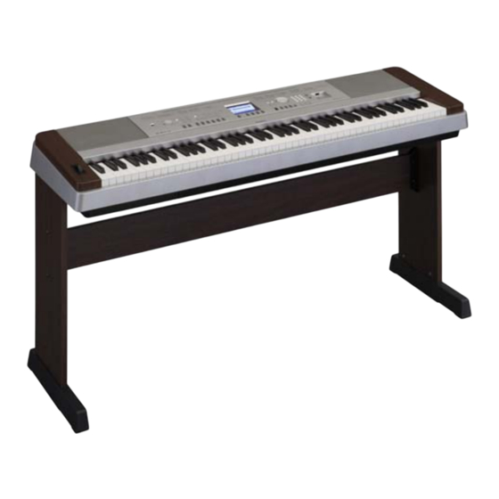
DGX-640W
CONTENTS
SPECIFICATIONS ..................................................................... 3
PANEL LAYOUT ....................................................................... 4
CIRCUIT BOARD LAYOUT& WIRING ...................................... 6
BLOCK DIAGRAM.................................................................... 8
DISASSEMBLY PROCEDURE ................................................ 9
LSI PIN DESCRIPTION .......................................................... 20
CIRCUIT BOARDS .................................................................. 24
TEST PROGRAM .................................................................... 33
BACKUP and INITIALIZATION ................................................ 38
USER DATA BACKUP ............................................................. 39
SYSTEM BOOTING FLOW CHART ....................................... 45
PARTS LIST
OVERALL CIRCUIT DIAGRAM
SERVICE MANUAL
DGX-640C
Copyright (c) Yamaha Corporation. All rights reserved.
HAMAMATSU, JAPAN
'10.04
Advertisement
Table of Contents


Need help?
Do you have a question about the Portable grand DGX-640W and is the answer not in the manual?
Questions and answers