Advertisement
PK
001759
/
SERVICE MANUAL
CONTENTS
SPECIFICATIONS .................................................................... 3
PANEL LAYOUT ........................................................................ 4
CIRCUIT BOARD LAYOUT & WIRING ..................................... 6
BLOCK DIAGRAM .................................................................... 8
DISASSEMBLY PROCEDURE ................................................. 9
LSI PIN DESCRIPTION .......................................................... 14
IC BLOCK DIAGRAM .............................................................. 17
CIRCUIT BOARDS ................................................................. 18
TEST PROGRAM ................................................................... 26
INITIALIZATION ...................................................................... 30
USER DATA BACKUP............................................................. 31
MIDI IMPLEMENTATION CHART ........................................... 35
MIDI DATA FORMAT ............................................................... 36
PARTS LIST
OVERALL CIRCUIT DIAGRAM
Copyright (c) Yamaha Corporation. All rights reserved. PDF
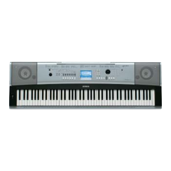
DGX-520
YPG-525
HAMAMATSU, JAPAN
...
...'06.03
Advertisement
Table of Contents


Need help?
Do you have a question about the PortableGrand DGX-520 and is the answer not in the manual?
Questions and answers