Advertisement
Available languages
Available languages
Quick Links
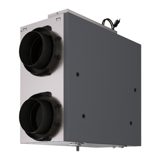
VNT5150 & VNT5200 Series ERV/HRV Ventilation Systems
PARTS IN THE BOX
•
Ventilator
•
Hanging Chain Kit
•
Hardware Kit
•
1/2 inch Drain Hose and Drain Fitting
External Damper Wire harness
•
•
Wiring Terminal Blocks
•
Duct Collars
•
Installation Guide
MODELS
•
VNT5200E2000 200 CFM Energy Recovery Ventilator
•
VNT5200H2000 200 CFM Heat Recovery Ventilator
•
VNT5150E2000 150 CFM Energy Recovery Ventilator
•
VNT5150H2000 150 CFM Heat Recovery Ventilator
Your ventilation system should be installed in conformance with the appropriate provincial requirements or, in the
absence of such requirements, with the current edition of the National Building Code, and / or ASHRAE's "Good
Engineering Practices".
REQUIREMENTS AND STANDARDS
•
Complies with the UL 1812 requirements regulating the construction and installation of heat recovery
ventilators
•
Complies with the CSA C22.2 no. 113 standard applicable to ventilators
•
Complies with the CSA F326 requirements regulating the installation of heat recovery ventilators
•
Energy recovery core is certified for mold and bacteria resistance
•
Technical data was obtained from published results of test relating to CSA C439 Standards
•
This product in conjunction with a T10+ thermostat with firmware REV. 03.03.05.00 or higher is consistent
with the requirements of Title 24, Part 6 Sections 150.1(c)7A, 150.2(b)1E, Table 150.1-A; JA6.1; and the
Residential Alternative Calculation Method (RACM) Reference Manual
PROFESSIONAL INSTALLATION GUIDE
VNT5150H
models are not
ENERGY STAR®
certified
33-00670EF-01
Advertisement

Subscribe to Our Youtube Channel
Related Manuals for Honeywell Home VNT5150 Series


Summary of Contents for Honeywell Home VNT5150 Series
- Page 1 VNT5150 & VNT5200 Series ERV/HRV Ventilation Systems PROFESSIONAL INSTALLATION GUIDE PARTS IN THE BOX • Ventilator • Hanging Chain Kit • Hardware Kit • 1/2 inch Drain Hose and Drain Fitting External Damper Wire harness • • Wiring Terminal Blocks •...
- Page 2 Before installation careful consideration must be given to how this system will operate if connected to any other piece of mechanical equipment, i.e. a forced air furnace or air handler operating at a higher static pressure. After installation, the compatibility of the two pieces of equipment must be confirmed by measuring the airflow of the Heat/Energy Recovery Ventilator using the balancing procedure found in this file.
- Page 3 Table of Contents Determining your airflow requirement ............... .2 Installation examples Fully dedicated system .
- Page 4 Determining your airflow requirement Room count method Room classification Number of CFM (L/s) CFM required rooms Master bedroom x 10 L/s (20 CFM) Basement yes or no if yes add 10 L/s (20 CFM if no = 0 Bedrooms x 5 L/s (10 CFM) Living room x 5 L/s (10 CFM) Others...
- Page 5 Installation examples Installation examples The way your heat/energy-recovery ventilator is installed can make a significant difference to the electrical energy you use. To minimize the electricity use of the heat/energy-recovery ventilator, a stand-alone fully ducted installation is recommended. If you choose a simplified installation that operates your furnace air handler for room-to-room ven- tilation, an electrically efficient furnace that has an electronically commutated (EC) variable speed blower motor will minimize your electrical energy consumption and operating cost.
- Page 6 Installation examples (continued) Installation examples (continued) Direct connection of the fresh air to living area to the return plenum of the air handler (stale air drawn from key areas of home). Suggested installation for: • Central furnace (air handling unit or central air conditioners) •...
- Page 7 Installation examples (continued) Installation examples (continued) Direct connection of both the HRV/ERV supply air stream and exhaust air stream to the furnace cold air return. Suggested installation for: • When bathroom and kitchen already have local exhaust system. • May be suitable for retrofitting.. Benefits: Least expensive installation type.
- Page 8 Exterior ducting installation Exterior ducting installation Weatherhood location OUTSIDE CORNER INSIDE CORNER • Decide where your intake and exhaust hoods will be 36" (1m) 36” (1m) located. Locating the intake weatherhood 3' (900mm) min. INTAKE EXHAUST • Should be located upstream (if there are prevailing winds) from the exhaust outlet.
- Page 9 Steps for hood installation: 1. Using the duct con- 2. Pull the insulated flexible 4. Using a caulking gun, 3. Push the nection of the outside duct through the opening seal around both hoods to hood into the opening hood, outline the intake until it is well extended and prevent any leaks.
- Page 10 Interior ducting installation Interior ducting installation • To maximize airflow through the ductwork system, all ducts should be kept short and have as few bends or elbows as possible. • 45º elbows are preferable to 90º. • Use “Y“ ducts instead of “T” ducts whenever possible. •...
- Page 11 Supply air grilles location In homes without a forced air furnace, fresh air should be supplied to all habitable rooms, including bedrooms and living areas. It should be supplied from high wall or ceiling locations. Grilles that diffuse the air comfortably are rec- ommended.
- Page 12 Mounting - Chain mount Mounting - Chain mount 1. Place fastening hooks 2. Take flat screwdriver 3. Hang the unit by slip- 4. Install a spring on each on the strapping board or and slightly pull on ping a link onto the hang- chain.
- Page 13 Airflow balancing Airflow balancing Fresh HIGH HIGH HIGH Balancing must be completed using the VNTBAL2000 Touchscreen Balancing Control (sold separately). After the unit is balanced, the Fresh Air Stale Air wall control may either be left in the home as the ventilator control, from Outside from Home or replaced with a different control for contractors who only use the...
- Page 14 Wiring Diagram - VNT5150 & VNT5200 Series VNT5150 & VNT5200 Series ERV/HRV Ventilation Systems 33-00670EF-01...
- Page 15 Wiring Diagram - VNT5150 & VNT5200 Series - (cont'd) Controls Controls Ensure that the unit is not plugged in when connecting the control. The wiring connectors can be removed for easier connection. Control Features Wiring to ventilator VNTBAL2000 Can NOT be used with another Central control. Required for balancing at time of installation.
- Page 16 Wiring Diagram - VNT5150 & VNT5200 Series - (cont'd) Damper Wiring Damper Wiring Harness included in box. Powered by 24 VAC internal transformer in ventilator. Molex plug to ventilator Black wire from harness* White wire from harness M39477 Auxiliary connector for external damper. Wire harness, damper not included.
- Page 17 Wiring Diagram - VNT5150 & VNT5200 Series - (cont'd) Wiring diagram to furnace For a furnace connection to a cooling system On some newer furnaces and older thermostats, energizing the R and G terminal at the furnace has the effect of energizing the Y at the thermostat and thereby turning on the cooling system.
- Page 18 Troubleshooting Problem Causes Solutions Air is too dry Dehumidistat control is set too low If a dehumidistat control is used on the ventilator, verify the setting on that control is not too low. HRV/ERV out of balance Contractor should balance HRV/ERV airflows Air is too humid Dehumidistat control is set too high If a dehumidistat control is used, verify the setting on that control.
- Page 19 HRV/ERV Maintenance Chart Maintenance Required Recommended Frequency Date Maintenance Performed Check and Clean Filters Every 3 months or if dirty Check Heat Recovery Core Every 6 months Check Drain Pan and Lines Every 3 months Vacuum the Inside of the Unit Annually Clean and Un-block Annually...
- Page 20 33-00670EF-01 SA Rev. 06-24 © 2024 Resideo Technologies, Inc. All rights reserved. The Honeywell Home trademark is used under license from Honeywell International, Inc. This product is manufactured by Resideo Technologies, Inc. and its affiliates. Tous droits réservés. La marque de commerce Honeywell Home est utilisée avec l’autorisation d’Honeywell International, Inc.
- Page 21 Systèmes de ventilation ERV/HRV séries VNT5150 et VNT5200 GUIDE D’INSTALLATION PROFESSIONNELLE PIÈCES DANS LA BOÎTE • Ventilateur • Kit de suspension • Vis et matériel d'assemblage • Tuyau de vidange et raccord 1/2 p. • Câblage pour volet externe • Bornier de raccordement •...
- Page 22 Avant de procéder à l’installation, examinez avec soin la façon dont le système fonctionnera s’il est relié à tout autre appareil mécanique, notamment une fournaise à air pulsé ou un appareil de traitement d’air dont la pression statique est plus élevée. Une fois l’installation terminée, la compatibilité...
- Page 23 Table des Matières Déterminer vos besoins de ventilation ..............22 Exemples d'installation Système entièrement dédié...
- Page 24 Déterminer vos besoins de ventilation Méthode par nombre de pièces Liste des pièces Nombre Pi³/min (L/s) PCM Requis de pièces Chambre principale x 10 L/s (20 pi³/min) Sous-sol oui ou non Si oui, ajoutez 10 L/s (20 pi³/min Sinon = 0 Chambre à...
- Page 25 Exemples d'installation Exemples d'installation La manière dont on a installé votre VRC/VRE peut faire une différence considérable quant à l’énergie électrique que vous utilisez. Afin de réduire la consommation d’électricité du VRC/VRE, on recommande une installation autonome entièrement canalisée. Si vous choisissez une installation simplifiée qui actionne l’appareil de traitement d’air de votre générateur d’air chaud aux fins d’une ventilation de pièce en pièce, un générateur d’air chaud qui consomme peu d’électricité...
- Page 26 Exemples d'installation (suite) Exemples d'installation (suite) Raccordement direct du flux d’air d’approvisionnement à la bouche de reprise d’air de la fournaise. (L’air vicié est aspiré à partir des endroits clés de la maison.) Installation suggérée pour: • Fournaise centrale (unité de traitement d’air, air climatisé central) •...
- Page 27 Exemples d'installation (suite) Exemples d'installation (suite) Raccordement direct du flux d’air d’approvisionnement et du flux d’air évacué du vrc/vre à la bouche d’air de la four- naise. Installation suggérée pour: • Lorsque la salle de bain et la cuisine ont déjà un système d’échappement. •...
- Page 28 Installation des conduits extérieurs Installation des conduits extérieurs Emplacement des clapets • Décidez de l’emplacement des clapets d’aspiration et d’évacuation. Coin intérieur Coin extéreur 36po (1m) 36po (1m) Emplacement du clapet d’aspiration • Doit être situé en amont de la sortie d’évacuation (en 3pi (900 mm) Apport min.
- Page 29 Étapes de l’installation du clapet: 1. Tracez le contour 2. Faites passer le con- 3. Enfoncez le clapet dans 4. À l’aide d’un pistolet du collet du clapet duit flexible isolé dans à calfeutrer, calfeutrez l’ouverture. Fixez le clapet externe pour découper l’ouverture jusqu’à...
- Page 30 Installation des conduits intérieurs (suite) Installation des conduits intérieurs (suite) Raccords d’Air Une catégorie de flexible ne répond pas aux exigences d'un conduit d'Air par rapport au Standard UL 181 catégorie de conduit d'air (n'est pas à l'épreuve de la pénétration de la flamme, de la perforation et la résistance à...
- Page 31 Installation du VRC/VRE • Assurez-vous d'avoir une source d'alimentation près. (120 volts, 60Hz) • Choisissez un emplacement où il y a possibilité de montage sur des poutres de support. • L'unité doit être au niveau afin d'assurer un drainage approprié. •...
- Page 32 Installation du tuyau d'écoulement Installer tout d’abord l’adapteur de drain dans le trou au fond de l’appareil puis fixer en utilisant l’écrou. Serrer l’écrou à la main, ensuite avec une cléanglaise faite un demi tour pour assurer l’étenchité. Installer le tuyau de condensat. Insérez le tube de condensat en poussant le conduit en plastique transparent sur le drain adaptateur.
- Page 33 Équilibrage Équilibrage HAUT Air frais ÉLEVÉ HAUT L’équilibrage doit être réalisé à l’aide de la commande d'équilibrage à écran LO W LO W Air vicié Air frais de tactile VNTBAL2000 (vendu séparément). Une fois l'appareil équilibré la com- de la maison l'extérieur mande murale peut être laissée dans la maison comme commande du venti- lateur, ou remplacée par une commande différente pour les entrepreneurs qui...
- Page 34 Schémas électriques - Séries VNT5150 et VNT5200 Systèmes de ventilation ERV/HRV séries VNT5150 et VNT5200 33-00670EF—01...
- Page 35 Schémas électriques - Séries VNT5150 et VNT5200 (suite) (suite) Commandes murales Commandes murales Assurez-vous que l’appareil n’est pas branché lors de la connexion de la commande. Les con- necteurs de câblage peuvent être retirés pour une connexion plus facile. Commandes Caractéristiques Câblage au ventilateur VNTBAL2000...
- Page 36 Schémas électriques - Séries VNT5150 et VNT5200 (suite) (suite) Câblage du volet Câblage du volet Prise molex au ventilateur Fil noir du câble* Fil blanc du câble M39477 Connecteur auxiliaire pour volet. Câbles, volet non inclus. EARD volet MF39469 *La polarité des fils n'a pas d'importance Systèmes de ventilation ERV/HRV séries VNT5150 et VNT5200 33-00670EF—01...
- Page 37 Schémas électriques - Séries VNT5150 et VNT5200 (suite) (suite) Connexion électrique à une fournaise Dans le cas d'une fournaise raccordée à un système de refroidissement Sur certaines nouvelles fournaises, et certains thermostats plus anciens, la mise sous tension des bornes R et G de la fournaise provoque la mise sous tension de la borne Y du thermostat et conséquemment la mise sous ten- sion du système de refroidissement.
- Page 38 Dépannage Problème Causes Solutions L’air est trop sec Le déshumidistat est réglé trop bas Si une commande de déshumidistat est utilisée sur le ventilateur, vérifiez que le réglage de cette commande n'est pas trop bas. Le VRC/VRE est déséquilibré L’entrepreneur doit équilibrer les flux d’air des VRC et des VRE. L’air est trop humide Le déshumidistat est réglé...
- Page 39 Tableau d'entretien du vrc/vre Entretien requis Fréquence recommandée Date de l'entretien Vérifiez et nettoyez les filtres à chaque 3 mois, ou s'ils sont sales Vérifiez le noyau récupérateur À chaque 6 mois de chaleur Vérifiez le bac de récupération À chaque 3 mois et les tuyaux d'échappement Nettoyez l'intérieur de l'appareil À...
- Page 40 © 2024 Resideo Technologies, Inc. All rights reserved. The Honeywell Home trademark is used under license from Honeywell International, Inc. This product is manufactured by Resideo Technologies, Inc. and its affiliates. Tous droits réservés. La marque de commerce Honeywell Home est utilisée avec l’autorisation d’Honeywell International, Inc.
Need help?
Do you have a question about the VNT5150 Series and is the answer not in the manual?
Questions and answers