
Related Manuals for gassero ULTRABOX


Summary of Contents for gassero ULTRABOX
- Page 1 ULTRABOX FLOOR STANDING CONDENSING BOILERS INSTALLATION AND USER MANUAL ULTRABOX 660 ULTRABOX 1030 ULTRABOX 1330...
- Page 2 THIS MANUAL IS AN INSEPARABLE PART OF THE BOILER AND HAS TO BE STORED TOGETHER WITH THE BOILER. IF THIS MANUAL DAMAGED OR LOST CONTACT GASSERO FOR A NEW COPY. THE INFORMATION AND INSTRUCTIONS THAT ARE SPECIFIED IN THIS MANUAL APPLY ONLY FOR THE BOILER MODELS SPECIFIED IN PAGE 3.
- Page 3 MEANINGS OF THE SYMBOLS AND SAFETY MEANINGS OF THE SYMBOLS The symbols which are used in this document and their meanings are as follows: DANGER : Actions that are certainly not to be done. Material damage and severe personal damage may occur.
- Page 4 92/42/EEC Boiler Efficiency Directive (BED) GENERAL These installation and maintenance instructions are prepared for the floor standing condensing boilers specified below: ULTRABOX 660 ULTRABOX 1030 ULTRABOX 1330 CE LABEL: This boiler complies with the essential requirements of the relevant European directives. The CE marking certifies that the products meet the essential requirements of the applicable regulations in accordance with the type of label.
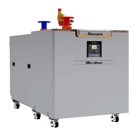
- Page 5 INTRODUCTION OF THE PRODUCT ULTRABOX is a condensing boiler which is modulated with a stainless steel heat exchanger and pre-mix burner for central heating and hot water production (optional).
- Page 6 Never switch off the power supply of the boiler when the outdoor air temperature falls below 0°C against the risk of freezing. Read the FROST PROTECTION section. ULTRABOX condensing boilers have to be installed in spaces that have necessary ventilation openings according to the current standards and applicable regulations ...
- Page 7 PACKAGING LABEL INFORMATION LABEL 60,0 620,0 58,4 602,0 64,8 665,0 1030 1027,0 2213 95,0 956,0 92,2 932,0 102,0 1030,0 1330 1333,0 3170 46,1 1235 44,8 1205,0 48,3 1333,0...
- Page 8 TECHNICAL SPECIFICATIONS DIMENSIONS ULTRABOX ULTRABOX ULTRABOX 1030 1330 A (Width) 960mm 1184mm 1184mm B (Length) 1846mm 2080mm 2490mm 1747mm 1982mm 1982mm C (Height) 1072mm 1385mm 1385mm D (Gas Connection) DN65(PN16) DN65(PN16) DN65(PN16) 939mm 1124mm 1124mm 139mm 139mm 139mm E (Boiler Outlet)
- Page 9 1 - Fan 13 - Flue Sensor 2 - Gas Valve 14 - Flue Outlet 3 - Control Panel 15 - Siphon 4 - Heat Exchanger 16 - Water Outlet Connection 5 - Ionization Electrode 17 - Water Inlet Connection 6 - Ignition Electrode 18 - Gas Inlet 7 - Ignition Transformer...
- Page 10 OPENING OF COVERS ULTRABOX boilers are equipped with movable covers for ease of maintenance and service. 1 - Remove the front cover 2 - Push the side covers back. 3 - Lift the cover to which the control panel is attached and lock the handle at the bottom.
- Page 11 INSTALLATION INTRODUCTIONS INSTALLATION 4.1.1 PACKAGING Ultrabox boilers are shipped on pallets as they are completely assembled, tested and protected against damage by wooden frame and nylon. PACKAGE INCLUDED : • User manual / Warranty certificate • Outdoor sensor • Immersion type temperature sensors •...
- Page 12 In old installations, iron oxide, sludge, sediment and similar deposits should be cleaned. The water in the system should be analyzed in terms of hardness, pH, iron content and conductivity. Gassero Water Specification Total Hardness Iron Conductivity °d (Not Diluted)
- Page 13 4.2.2 SAFETY VALVE ULTRABOX boilers are equipped with a safety valve. The hose of this safety valve must be connected to a drain. Manufacturer cannot be held liable for damages caused by water flow into the boiler or on the ground when excessive pressure is generated in the heating installation.
- Page 14 4.2.3 CONDENSATION WATER DRAIN Condensation water which is generated during to the combustion, transfers to the water drain connection by the syphon and drain hose. Condensation water is acidic and corrosive (approx. 2 ph). So all of the connections which are made for condensation water must be made with PP type pipes.
- Page 15 4.2.6 AUTOMATIC AIR RELIEF VALVE ULTRABOX boilers have an automatic relief valve for the evacuation of the air accumulated in the heat exchanger. However, for the evacuation of the air that may occur in the installation, it is necessary to place one or more automatic air relief valves in the appropriate places of the installation.
- Page 16 Pumps aren’t included in ULTRABOX model boilers. The WATER FLOW RATE primary pumps, which are determined according to the (m³/h) hydraulic pressure losses of the boiler, are offered by Gassero PUMP as an option. If a different primary pump is to be used, pump DELIVERY HEAD...
- Page 17 4.3.1 FLUE TYPES B23 = It is a flue system that takes the combustion air from the environment and throws flue gas to the outside. C43 = It is a flue system that takes the combustion air from the outside and throws flue gas to the outside with seperate flue pipes.
- Page 18 Electrical connections of the installation have to be made by qualified technical personnel in accordance with regulations and standards. Electrical connections of the boiler have to be made by Gassero authorized services. Electrical cables should not be passed near from hot surfaces (such as flow pipes).
- Page 20 4.4.2 OUTDOOR TEMPERATURE SENSOR When an outdoor temperature sensor installed, boiler will adjust supply temperature according outside temperature in order to provide energy saving without compromise the comfort. Outdoor Temperature Sensor has to be installed; North or northeast direction of the outside of the building, at a height of minimum 2,5m from the ground, not exposed to direct sunlight, straight side of the wall,...
- Page 21 INSTALLATION EXAMPLES...
- Page 25 - Flow Valve - Return Valve - Gas Valve - Non-return Valve - Pump - Strainer / Filter - Test Nipple - Manometer - Gas Regulator...
- Page 26 OPERATION GENERAL ULTRABOX boilers; Controls 3 heating zones. It could be increase with placing additional zone modules (optional). Calculates exact temperatures for each zone via sensors and outdoor temperature sensor. Saves and display the fault and error history.
- Page 27 DISPLAY CANCEL BUTTON – ESC Backlight display automatically turn off without operation. Used for to cancel the settings and return to upper menu Push any button to turn it on again. section. Screen displays information / settings below: Operation modes MANUAL CONTROL BUTTON Temperatures Parameters...
- Page 28 OPERATING MODE SELECTION ADJUSTING THE ROOM TEMPERATURE: The temperature (comfort value) of the room which is heated by the heating circuit-1 is set by the Navigation Button. The boiler will be activated and keep the room temperature constant to the set temperature. To adjust;...
- Page 29 FROST PROTECTION : It will be activated when the temperature of the water in the boiler falls below 4°C and activates the primary circulation pump. In order for the frost protection mode to be active, boiler's electrical switch must be switched on and the system water must be full.
- Page 30 MAIN FUNCTIONS Button Action Procedure Display / Function Zone 1 and zone 2 Actuate rotary knob left/right Comfort setpoint with blinking temperature Set room temperature Turn rotary knob Confirm with OK button Blinking temperature in 0,5 °C steps from 10 to 30 °C or wait 5 sec.
- Page 31 BMS – BOILER 0-10V MANAGEMENT 1) H3 output could use for 0-10V management. After cable connection, 5960 parameter should set ‘Consumer Request CC1 10V’ from configuration menu. 2) 5963-64-65-66 parameter should set for heat and value assignment. 3) Heating Circuit 5710 and 5715 parameter should set ‘OFF’ from configuration menu.
- Page 32 PARAMETERS Parameters of ULTRABOX boilers are divided into 4 groups according to their level: END USER PARAMETERS COMMISSIONING ENGINEER incorrect adjustments energy saving operation may not be observed and the whole system or some parts of the units may be damaged.
- Page 33 ERROR / FAULT CODES ULTRABOX boilers are equipped with a fault diagnosis system. When a malfunction code is displayed on both the Master and Slave boilers, the red light on the bottom of the control panel flashes with the no flame sign.
- Page 34 CASCADE ULTRABOX boilers can be used as a single boiler or as cascade for up to 16 boilers. Particularly during the season passes, the heat requirement of the system may be very low. Cascade systems run only 1 boiler to meet this low heat requirement and provide efficient operation.
- Page 35 10.1 EMISSION SETPOINTS 10.2 NOMINAL LOAD EMISSION SETTINGS Connect the Flue Gas Analyzer probe to the sampling point on the flue adapter. Make sure that the Flue Gas Analyzer which will be used to adjust the combustion settings is calibrated and functioning correctly.
- Page 36 10.4 GAS PRESSURE SWITCH Ultrabox boilers are equipped with a Gas Pressure Switch as a measure against high gas pressure. This value is adjusted to 50 mbar In cases where the mains pressure is higher than the set value, the gas pass is stopped and 132 (Gas pressure switch safety shut-down) error code will be displayed on the control panel.
- Page 37 This information should be added to the information provided by the consumer and the service history of the boiler should be established. Authorized Gassero service responsible should inform the consumer about the defects in the installation or location and advise on the solution of these defects.
- Page 38 Burner will be cleaned. - Burner surfaces/pores can be cleaned with a non-metal brush or compressed air. The burner gasket cap gasket (fuse) will be checked and has to be replaced if deformed. - If during the annual inspection, deposits are observed in the combustion chamber, it is necessary to proceed to the aspiration of these deposits while having as a preliminary, if required, brush the coils of the heat exchanger using a non-metal wire flexible brush.
- Page 39 Ignition and ionization electrodes of the boiler will be removed and cleaned or replaced if necessary. Distances between the electrodes and the burner are very important in terms of ignition and flame detection. - Distances which are shown below must be observed when adjusting the electrode distances. - Electrode gasket has to be replaced if the electrode is cleaned or replaced.
- Page 40 DISPOSAL When ULTRABOX boilers have to be disposed of, the procedures determined by the local authorities must be followed. Such wastes must be treated in accordance with the applicable regulations. ...
- Page 41 TROUBLE SHOOTING...
- Page 42 Nitrite protection should not be used in boilers with aluminum heat exchangers As GASSERO, we recommend flushing in the system to prolong the life of system and boilers. No acid-based products should be used during flushing. The water used in the installation must be city-water. Never use well-water The boiler must be serviced annually.
- Page 43 MANUFACTURER : Gassero Isi Teknolojileri Sanayi Limited Sirketi İstanbul Endüstri ve Ticaret Serbest Bölgesi 4.Sokak,No:8, 34957 Tuzla / Istanbul / TURKEY Phone : +90 216 394 09 85 -86 -87 : +90 216 394 24 91 www.gassero.com...
Need help?
Do you have a question about the ULTRABOX and is the answer not in the manual?
Questions and answers