Sign In
Upload
Download
Add to my manuals
Delete from my manuals
Share
URL of this page:
HTML Link:
Bookmark this page
Add
Manual will be automatically added to "My Manuals"
Print this page
×
Bookmark added
×
Added to my manuals
Manuals
Brands
Leica Manuals
Analytical Instruments
DD300
User manual
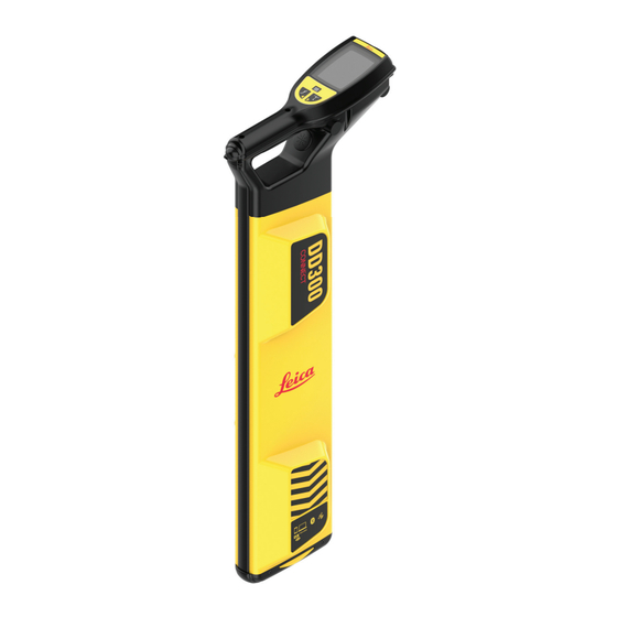
Leica DD300 Connect User Manual
Cable locator/transmitter
Hide thumbs
Also See for DD300 Connect
:
Quick manual
(16 pages)
1
2
3
4
5
6
7
8
9
10
11
12
13
14
15
16
17
18
19
20
21
22
23
24
25
26
27
28
29
30
31
32
33
34
35
36
37
38
39
40
41
42
43
44
45
46
47
48
49
50
51
52
53
54
55
56
57
58
59
60
61
62
63
64
65
66
67
68
69
70
71
72
73
74
75
76
77
78
79
80
81
82
83
84
85
86
87
88
89
90
91
92
page
of
92
Go
/
92
Bookmarks
Advertisement
Quick Links
Download this manual
User Manual
Version 1.1
English
Leica DD300 Connect - Cable
Locator
Leica DA300 Transmitter
Previous
Page
Next
Page
1
2
3
4
5
Advertisement
Need help?
Do you have a question about the DD300 Connect and is the answer not in the manual?
Ask a question
Questions and answers
Related Manuals for Leica DD300 Connect
Security Sensors Leica DD300 Quick Manual
Detection locators & accessories (16 pages)
Analytical Instruments Leica DISTO D810 touch Manual
Laser distance meter (44 pages)
Analytical Instruments Leica Disto D810 Touch User Manual
Laser distance meter (44 pages)
Analytical Instruments Leica DISTO D810 touch Manual
The original laser distance meter (44 pages)
Analytical Instruments Leica DISTO D810 touch Frequently Asked Questions Manual
(8 pages)
Analytical Instruments Leica DISTO D5 User Manual
Disto d5 laser distance meter (22 pages)
Analytical Instruments Leica DISTO D210 Manual
Laser distance meter (22 pages)
Analytical Instruments Leica DISTO D210 User Manual
Laser distance meter (14 pages)
Analytical Instruments Leica DISTO D2 User Manual
(43 pages)
Analytical Instruments Leica DISTO D8 Manual
The original laser distance meter (23 pages)
Analytical Instruments Leica DISTO D3a Manual
Laser distance meter (22 pages)
Analytical Instruments Leica DISTO BT Manual
Laser distance meter (22 pages)
Analytical Instruments Leica DISTO D510 How To Use Manual
(15 pages)
Analytical Instruments Leica DISTO D510 Frequently Asked Questions Manual
(7 pages)
Analytical Instruments Leica DISTO D510 Manual
The original laser distance meter (31 pages)
Analytical Instruments Leica DA300 User Manual
Cable locator/transmitter (92 pages)
This manual is also suitable for:
Da300
Print
Rename the bookmark
Delete bookmark?
Delete from my manuals?
Login
Sign In
OR
Sign in with Facebook
Sign in with Google
Upload manual
Upload from disk
Upload from URL


Need help?
Do you have a question about the DD300 Connect and is the answer not in the manual?
Questions and answers