Table of Contents
Advertisement
Quick Links
Advertisement
Table of Contents

Related Manuals for Diamond G65/6BFA11-N


Summary of Contents for Diamond G65/6BFA11-N
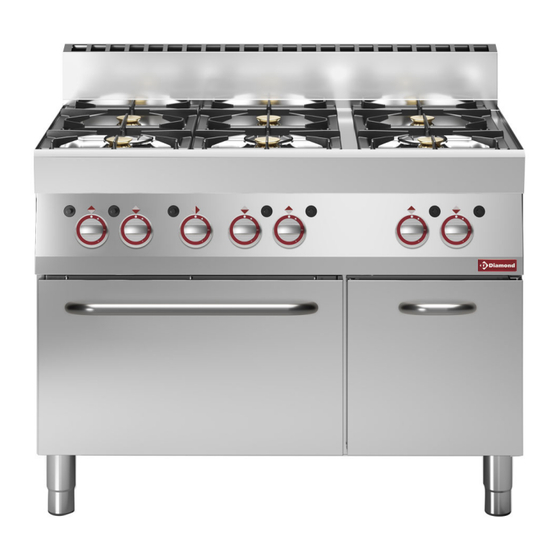
- Page 1 MOD : G65/6BFA11-N Production code : F65/40PCE/T 04/2024...
- Page 2 RANGE, GAS SOLID TOP 600-650 Installation-Use-Maintenance MOD. _60/30 PCG… _60/30 PCE… _CEG/70 _70/70 CFGS _60/60 PCG… _60/60 PCE… _CEG/110 _65/110 CFG _60/90 PCG… _60/90 PCE… _65/40 PG/40 P _65/110 CFGE _60/60 CFG _60/60 CFE _65/40 PCG _65/110 CFGG _60/60 CFGE _60/60 CFE/P 2/3 _65/70 PCG _65/40 PCE...
-
Page 3: Table Of Contents
UK - INSTALLATION – USE - MAINTENANCE ..........................23 GENERAL PRESCRIPTIONS ..................................23 DISPOSAL OF PACKING AND OF THE APPLIANCE ................................23 SAFETY DEVICES..........................................24 INSTRUCTIONS FOR INSTALLATION ................................24 REMINDERS FOR THE INSTALLER ....................................24 REFERENCE STANDARDS AND LAWS .................................... 24 UNPACKING .......................................... -
Page 4: Installation - Use - Maintenance
UK - INSTALLATION – USE - MAINTENANCE Unless they are supervised or instructed in its use by a person responsible for their safety. GENERAL PRESCRIPTIONS Do not leave de appliance unattended in presence of children and ensure that the latter do not have acces to the appliance. -
Page 5: Safety Devices
The packing is made using environmentally The appliance is equipped with a manual reset friendly materials. plastic recyclable safety thermostat that interrupts heating when components are: the operating temperature exceeds the maximum - the transparent cover, the bags containing the permitted value. -
Page 6: Unpacking
extractor hood. 5. UNPACKING " B11 " TYPE APPLIANCE Check the state of the packing and in the event of Fit the “B11” type appliance with a suitable fl ue, damage, ask the delivery person to inspect the available from the appliance manufacturer. Follow goods. -
Page 7: Conversion To Another Type Of Gas
Connect the power supply cable to the terminal board as shown in the wiring diagram supplied 8. CONVERSION TO ANOTHER with the appliance. TYPE OF GAS Secure the power supply cable with the cable clamp. Protect the power supply cable on the outside of Table Tab1 specifies: the appliance with a rigid plastic or metal pipe. -
Page 8: Commissioning
indicated in table TAB1. REPLACING THE NOZZLE AND THE MAIN BURNER Retighten nozzle UM. PRIMARY AIR REGULATION Reassemble all parts. For assembly, proceed in Remove the control panel. reverse order. Remove nozzle UM and replace it with the one indicated in table TAB1. Retighten nozzle UM. -
Page 9: Instructions For Use
Chapter “ INSTRUCTIONS FOR USE “ and check: service contract. The appliance is designed for professional use and - the gas supply pressure (see next Paragraph). must be operated by trained personnel. - the correct ignition of the burners and the The appliance is to be used for cooking food as effectiveness of the fumes removal system. -
Page 10: Using The Gas Hob
The pilot light can be lit by bringing an open flame up to the nozzle. Raise the central disc on the hotplate. MAX. FLAME MAIN BURNER IGNITION To light the main burner, turn the knob from “pilot MIN. FLAME on” to “max. flame”. For the minimum flame, turn the knob from “max. -
Page 11: Gas Oven 600 Series Use
The pilot light can be lit by bringing an open flame Press the knob for 5-10 seconds. The burner is up to the nozzle. Raise the central disc on the turned on electrically. hotplate. If the burner doesn’t turn on, open the oven door for 1 minute and repeat the operation. -
Page 12: Gas Stockpot Stove Use
BURNER IGNITION AND EXTINCTION BURNER IGNITION AND EXTINCTION The gas tap control knob has the following the control knob of the thermostatic tap has the positions: following positions use: PILOT IGNITION MINIMUM TEMPERATURE MAX. FLAME MIN. FLAME PILOT IGNITION INTERMEDIATE TEMPERATURES Press and turn knob to “pilot on”. -
Page 13: Electric Convection Oven Use
SWITCHING ON AND OFF MINIMUM TEMPERATURE The control knob has the following positions: INTERMEDIATE TEMPERATURES MINIMUM TEMPERATURE MAXIMUM WATER TEMPERATURE INTERMEDIATE TEMPERATURES SWITCHING ON Turn the thermostat knob to the chosen temperature setting for cooking. MAXIMUM WATER TEMPERATURE the yellow and the green indicator lamp turn on. The yellow indicator light switches off when the oven reaches the set temperature. -
Page 14: Prolonged Disuse
20. PROLONGED DISUSE OVEN LAMP Before any prolonged disuse of the appliance, proceed as follows: UPPER AND LOWER HEATING - Clean the appliance thoroughly. ELEMENTS - Rub stainless steel surfaces with a cloth soaked in vaseline oil to create a protective film. UPPER AND INNER HEATING - Leave pot lids open. -
Page 15: Instructions For Maintenance
repeatedly and dry thoroughly. See Chapter “ Instructions for installation “. 24. COMMISSIONING Do not use pan scourers or other iron items. Do not use chemical products containing chlorine. Do not use sharp objects which might scratch and See Chapter “ Instructions for installation “. damage the surfaces. -
Page 16: Replacing Components
Possible causes: - Hotplate defective. GAS OVEN ELECTRIC OVEN THE MAIN BURNER DOESN’T TURN ON Possible causes: THE APPLIANCE DOES NOT HEAT. - Insufficient gas supply pressure. - Blocked tubing or nozzle. Possible causes: - Defective gas tap or valve. - Temperature thermostat defective. - Page 17 - Remove and replace the component. - Reassemble all parts. For assembly, proceed in - Reassemble all parts. For assembly, proceed in reverse order. reverse order. REPLACING THE MAIN BURNER, PILOT BURNER, THERMOCOUPLE AND IGNITER. REPLACING THE MAIN BURNER, PILOT BURNER, THERMOCOUPLE AND IGNITER.
-
Page 18: Cleaning The Interior
- Undo the screw securing the element to the oven - Hotplate and pull the element out by approx. 10 cm. - Indicator light - Reassemble all parts. For assembly, proceed in reverse order. ELECTRIC OVEN - Control knob 27. CLEANING THE INTERIOR - Working thermostat - Safety thermostat - Heating element...
Need help?
Do you have a question about the G65/6BFA11-N and is the answer not in the manual?
Questions and answers