Advertisement
Quick Links
User's Guide
VES1724 Series
24-port VDSL2 Box DSLAM
Default Login Details
In-band IP
Address
Out-of-band IP
Address
User Name
Password
Copyright © 2021 Zyxel Communications Corporation
http://192.168.1.1
http://192.168.0.1
admin
1234
Version 1.00 Edition 6, 11/2021
Advertisement

Related Manuals for ZyXEL Communications VES1724 Series


Summary of Contents for ZyXEL Communications VES1724 Series
- Page 1 User’s Guide VES1724 Series 24-port VDSL2 Box DSLAM Default Login Details Version 1.00 Edition 6, 11/2021 In-band IP http://192.168.1.1 Address Out-of-band IP http://192.168.0.1 Address User Name admin Password 1234 Copyright © 2021 Zyxel Communications Corporation...
- Page 2 Screenshots and graphics in this book may differ slightly from your product due to differences in your product firmware or your computer operating system. Every effort has been made to ensure that the information in this manual is accurate. VES1724 Series User’s Guide...
- Page 3 Figures in this user’s guide may use the following generic icons. The VES1724 icon is not an exact representation of your device. VES1724 DSL Router Generic Switch Switch Router Server Street Pole Street Cabinet Home Hotel Branch Office VES1724 Series User’s Guide...
- Page 4 CFM ..............................282 VLAN Mapping ........................... 287 Layer 2 Protocol Tunneling ........................ 291 DoS Prevention ............................ 295 PPPoE IA ............................... 297 ADSL Fallback ............................. 305 Error Disable ............................312 Link Layer Discovery Protocol (LLDP) ....................316 VES1724 Series User’s Guide...
- Page 5 Syslog ..............................405 Loop Diagnostic ..........................408 MAC Table ............................412 ARP Table ............................415 Hardware Information ........................417 CFM Action ............................418 IPv6 Cache ............................427 Online Users ............................432 Troubleshooting ..........................433 Product Specifications ........................437 VES1724 Series User’s Guide...
- Page 6 3.1.1 Power Connections ......................28 3.1.2 Gigabit Ethernet Ports ......................29 3.1.3 Mini-GBIC Slots ........................30 3.1.4 Management Port ........................ 31 3.1.5 Console Port .......................... 32 3.1.6 ALARM Slot ..........................32 3.2 LEDs ..............................33 3.3 Fan Module ............................. 34 VES1724 Series User’s Guide...
- Page 7 7.1 Overview ............................57 7.2 Port Status Summary ........................57 7.2.1 VDSL Port Status Change ..................... 59 7.2.2 VDSL Summary ........................59 7.2.3 VDSL Port Details ........................60 7.2.4 Port Details ..........................71 7.2.5 Bonding Group Details ......................73 VES1724 Series User’s Guide...
- Page 8 9.3.2 VDSL Line Profile Setup > ADSL/VDSL Protocol ..............115 9.3.3 VDSL Line Profile Setup > Rate Adaptive ................116 9.3.4 VDSL Line Profile Setup > MIB PSD Mask ................118 9.3.5 VDSL Line Profile Setup > DPBO ..................119 VES1724 Series User’s Guide...
- Page 9 Static MAC Forward Setup ......................157 11.1 Overview ............................. 157 11.2 Configuring Static MAC Forwarding ..................157 Chapter 12 Static Multicast Forward Setup .......................159 12.1 Static Multicast Forwarding Overview ..................159 12.2 Configuring Static Multicast Forwarding .................. 160 VES1724 Series User’s Guide...
- Page 10 17.4 Link Aggregation Setting ......................189 17.5 Link Aggregation Control Protocol ..................190 17.6 Static Trunking Example ......................192 Chapter 18 Port Authentication ..........................193 18.1 Port Authentication Overview ....................193 18.1.1 IEEE 802.1x Authentication ....................193 VES1724 Series User’s Guide...
- Page 11 23.1 VLAN Stacking Overview ......................217 23.1.1 VLAN Stacking Example ....................217 23.2 VLAN Stacking Port Roles ......................218 23.3 VLAN Tag Format ........................218 23.3.1 Frame Format ........................219 23.4 Configuring VLAN Stacking ....................... 219 23.4.1 Port-based Q-in-Q ......................221 VES1724 Series User’s Guide...
- Page 12 25.3 Supported RADIUS Attributes ....................254 25.3.1 Attributes Used for Authentication .................. 255 25.3.2 Attributes Used for Accounting ..................255 Chapter 26 IP Source Guard ..........................258 26.1 IP Source Guard Overview ......................258 26.1.1 DHCP Snooping Overview ....................258 VES1724 Series User’s Guide...
- Page 13 30.1 Layer 2 Protocol Tunneling Overview ..................291 30.1.1 Layer 2 Protocol Tunneling Mode ................... 292 30.2 Configuring Layer 2 Protocol Tunneling ................... 292 Chapter 31 DoS Prevention ..........................295 31.1 DoS Prevention Overview ......................295 31.2 Configuring DoS Prevention ...................... 295 VES1724 Series User’s Guide...
- Page 14 35.5.1 LLDP Configuration Basic TLV Setting ................329 35.5.2 LLDP Configuration Org-specific TLV Setting ..............331 35.6 LLDP Statistics ..........................332 Chapter 36 IPv6 Source Guard ...........................335 36.1 Overview ............................. 335 36.2 IPv6 Source Guard ........................335 VES1724 Series User’s Guide...
- Page 15 39.3.4 Configuring DHCP Global Relay ..................360 39.3.5 Global DHCP Relay Configuration Example ..............363 39.4 Configuring DHCP VLAN Settings ..................364 39.4.1 Example: DHCP Relay for Two VLANs ................367 39.5 DHCPv6 LDRA ..........................368 39.5.1 DHCPv6 Counter ....................... 372 VES1724 Series User’s Guide...
- Page 16 41.8.1 Internet Explorer Warning Messages ................397 41.8.2 Mozilla Firefox Warning Messages ................... 398 41.8.3 The Port Status Screen ...................... 400 41.9 Service Port Access Control ....................400 41.10 Remote Management ......................401 Chapter 42 Diagnostic............................403 VES1724 Series User’s Guide...
- Page 17 48.1.1 CFM Action Examples ....................... 419 Chapter 49 IPv6 Cache ............................427 49.1 Overview ............................. 427 49.2 Neighbor Cache ........................428 49.3 Path MTU ............................429 49.4 Router ............................430 Chapter 50 Online Users............................432 50.1 Online Users ..........................432 VES1724 Series User’s Guide...
- Page 18 51.2 Switch Access and Login ......................434 51.3 Switch Configuration ........................436 Chapter 52 Product Specifications........................437 Appendix A Customer Support ..................... 452 Appendix B Common Services ...................... 457 Appendix C Legal Information ...................... 460 Index ..............................465 VES1724 Series User’s Guide...
- Page 19 User’s Guide...
- Page 20 Internet access to all tenants. Note that VDSL service can coexist with voice service on the same line. Have qualified service personnel install the Switch in a restricted access area, such as a building’s basement or telco room. VES1724 Series User’s Guide...
- Page 21 1.3 Ways to Manage the Switch Use any of the following methods to manage the Switch. • Web Configurator. This is recommended for management of the Switch using a (supported) web browser. See Chapter 4 on page VES1724 Series User’s Guide...
- Page 22 Switch to its factory default settings. If you backed up an earlier configuration file, you would not have to totally re-configure the Switch. You could simply restore your last configuration. VES1724 Series User’s Guide...
- Page 23 Remove the adhesive backing from the rubber feet. Attach the rubber feet to each corner on the bottom of the Switch. These rubber feet help protect the Switch from shock or vibration and ensure space between devices when stacking. VES1724 Series User’s Guide...
- Page 24 2.3.2 Attaching the Mounting Brackets to the Switch Position a mounting bracket on one side of the Switch, lining up the four screw holes on the bracket with the screw holes on the side of the Switch. VES1724 Series User’s Guide...
- Page 25 Connect the frame ground on the front panel using an M4 x 6mm machine screw with 2 suitable lock washers to a building’s protective earthing terminals. Qualified service personnel must confirm that the building’s protective earthing terminal is valid. VES1724 Series User’s Guide...
- Page 26 Use a 18 AWG or larger green-and-yellow frame ground wire. Connect the frame ground before you connect any other cables or wiring. Figure 6 VES1724-55C Frame Ground Frame Ground Figure 7 VES1724-56 Frame Ground Frame Ground Figure 8 VES1724-56B2 Frame Ground Frame Ground VES1724 Series User’s Guide...
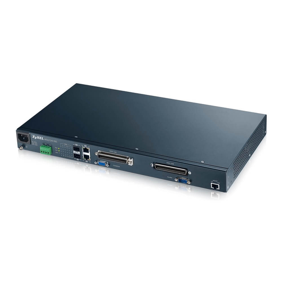
- Page 27 Figure 9 VES1724-55C Front Panel Figure 10 VES1724-56 Front Panel Figure 11 VES1724-56B2 Front Panel The following table describes the port labels on the front panel. Table 1 Front Panel Connections LABEL DESCRIPTION Power Connect an appropriate power supply. Connection VES1724 Series User’s Guide...
- Page 28 (bare) wires can be seen or touched. The Switch has two sets of DC power terminals. Figure 12 VES1724-55C and VES1724-56B2 DC Power Terminals Set 1 Set 2 VES1724 Series User’s Guide...
- Page 29 When the Switch’s auto-negotiation is turned off, an Ethernet port uses the pre-configured speed and duplex mode when making a connection, thus requiring you to make sure that the settings of the peer Ethernet port are the same in order to connect. VES1724 Series User’s Guide...
- Page 30 Press the transceiver firmly until it clicks into place. The Switch automatically detects the installed transceiver. Check the LEDs to verify that it is functioning properly. Close the transceiver’s latch (latch styles vary). Connect the fiber optic cables to the transceiver. VES1724 Series User’s Guide...
- Page 31 Figure 18 Transceiver Removal Example 3.1.4 Management Port The MGMT (management) port is used for local management. Connect directly to this port using an Ethernet cable. You can configure the Switch via Telnet or the Web Configurator. VES1724 Series User’s Guide...
- Page 32 An open circuit for pins 4 and 8 indicates no alarm status. A closed circuit indicates an alarm status. Pin 5 and Pin 9 An open circuit for pins 5 and 9 indicates no alarm status. A closed circuit indicates an alarm status. VES1724 Series User’s Guide...
- Page 33 The port is not connected at 10 Mbps or to an Ethernet device. Amber Blinking The system is transmitting/receiving to/from an Ethernet device. The port is connected at 100 Mbps. The port is not connected at 100 Mbps or to an Ethernet device. VES1724 Series User’s Guide...
- Page 34 Remove the screw from the front of the fan module. Slide out the fan module. Slide the new fan module into the fan module slot. Put the fan module screw back in and tighten it. Re-connect the power (see Section 3.1.1 on page 28). VES1724 Series User’s Guide...
- Page 35 Chapter 3 Hardware Overview Figure 20 Removing the Fan Module VES1724 Series User’s Guide...
- Page 36 The Sign in screen appears. The default username is admin and associated default password is 1234. Note: Alternatively, you can log into the Web Configurator through an in-band (non-MGMT) port. The default in-band management IP address is 192.168.1.1. VES1724 Series User’s Guide...
- Page 37 The Port Status screen displays when you access the Web Configurator. Figure 22 Web Configurator: Port Status Screen The Web Configurator is divided into these parts: • A - Title Bar • B - Navigation Panel • C - Main Window VES1724 Series User’s Guide...
- Page 38 Click this to go to the Port Status screen of the Switch. Logout Click this link to logout of the Web Configurator. Help Click this link to display web help pages. The help pages provide descriptions for all of the configuration screens. VES1724 Series User’s Guide...
- Page 39 The following table describes the links in the navigation panel. Table 6 Navigation Panel Links LINK DESCRIPTION Basic Setting System Info Use this screen to display general system and hardware monitoring information. General Setup Use this screen to configure general identification information about the Switch. VES1724 Series User’s Guide...
- Page 40 VLAN. Classifier Use this screen to configure the Switch to group packets based on the specified criteria. Policy Rule Use this screen to configure the Switch to perform special treatment on the grouped packets. VES1724 Series User’s Guide...
- Page 41 Use this screen to view the MAC addresses (and types) of devices attached to what ports and VLAN IDs. ARP Table Use this screen to view the MAC addresses – IP address resolution table. Hardware Use this screen to check hardware detailed information such as CPU, packet buffer, memory Information utilization. VES1724 Series User’s Guide...
- Page 42 Note: Use the Save link when you are done with a configuration session. 4.5 Switch Lockout You could block yourself (and all others) from using in-band-management (managing through the data ports) if you do one of the following: VES1724 Series User’s Guide...
- Page 43 Type atlc after the “Enter Debug Mode” message. Wait for the “Starting XMODEM upload” message before activating XMODEM upload on your terminal. After a configuration file upload, type atgo to restart the Switch. VES1724 Series User’s Guide...
- Page 44 Figure 25 Web Configurator: Logout Screen 4.8 Help The Web Configurator’s online help has descriptions of individual screens and some supplementary information. Click the Help link from a Web Configurator screen to view an online help description of that screen. VES1724 Series User’s Guide...
- Page 45 Connect your computer to an in-band Ethernet port on the Switch. Make sure your computer is in the same subnet as the Switch. Open your web browser and enter 192.168.1.1 (the default IP address) in the address bar to access the Web Configurator. See Section 4.2 on page 36 for more information. VES1724 Series User’s Guide...
- Page 46 In this example, you want to configure port 1 and port 2 as members of VLAN 2. Figure 27 Initial Setup Network Example: VLAN Internet 192.168.1.x 192.168.1.x VLAN1 VLAN2 Click Advanced Application > VLAN in the navigation panel and click the Static VLAN link. VES1724 Series User’s Guide...
- Page 47 VLAN group that the tag defines. In the example network, configure 2 as the port VID on port 1 so that any untagged frames received on that port get sent to VLAN 2. VES1724 Series User’s Guide...
- Page 48 Enter 2 in the PVID field for port 1 and click Apply to save your changes back to the run-time memory. Settings in the run-time memory are lost when the Switch’s power is turned off. VES1724 Series User’s Guide...
- Page 49 Follow the steps below to configure ports 2 and 18 as a member of VLAN 102. Access the Web Configurator through the Switch’s management port. Go to Basic Setting > Switch Setup and set the VLAN type to 802.1Q. Click Apply to save the settings to the run-time memory. VES1724 Series User’s Guide...
- Page 50 Select Fixed to configure ports 2 and 18 to be a permanent member of this VLAN. To ensure the VLAN- unaware devices, such as computers can receive frames properly, clear the Tx Tagging check box for port 2 to have the Switch remove VLAN tags before sending. Click Add. VES1724 Series User’s Guide...
- Page 51 Chapter 6 Tutorials Figure 31 Tutorial: Create a Static VLAN Click the VLAN Status link in the Static VLAN screen and then the VLAN Port Setting link in the VLAN Status screen. VES1724 Series User’s Guide...
- Page 52 Enter 102 in the PVID field for ports 2 and 18 to add a tag to incoming untagged frames received on these ports so that the frames are forwarded to the VLAN group that the tag defines. Click Apply. Figure 33 Tutorial: Set PVID for Untagged Frames Received on Ports 2 and 18 VES1724 Series User’s Guide...
- Page 53 In the VID field, enter the ID of the VLAN group (102 in this example) to which you want this management IP address to belong. Enter the IP address of the default gateway (192.168.2.254 for example) in the Default Gateway field. Click Add. Figure 34 Tutorial: Set Management IP Address for VLAN 102 VES1724 Series User’s Guide...
- Page 54 Leave other fields empty or as default unless something needs to be specified. Click Add. Figure 35 Tutorial: Set DHCP Server and Relay Information Click the Save link in the upper right corner of the Web Configurator to save your configuration permanently. VES1724 Series User’s Guide...
- Page 55 The Switch can then forward the DHCP packets between the clients and DHCP server in VLAN 1. 6.1.5 Testing the Connection Check the client A's IP address. If it did not receive the IP address 192.168.2.3, make sure the devices are connected and configured properly. VES1724 Series User’s Guide...
- Page 56 Technical Reference...
- Page 57 The Port Status screen of the Web Configurator displays a port statistical summary with links to each port showing statistical details. 7.2 Port Status Summary To view the port statistics, click Status in all Web Configurator screens to display the Status screen as shown next. VES1724 Series User’s Guide...
- Page 58 If STP is disabled, this field displays FORWARDING if the link is up, otherwise, it displays STOP. LACP This fields displays whether LACP (Link Aggregation Control Protocol) has been enabled on the port. VES1724 Series User’s Guide...
- Page 59 LD_DONE LD_TEST 7.2.2 VDSL Summary To view VDSL statistics, click VDSL Summary in the Status screen. Click Clear next to an entry to reset that connection. All values for that connection will be reset to 0. VES1724 Series User’s Guide...
- Page 60 Use this screen to check status and detailed performance data for an individual port on the Switch. Note: This screen refreshes automatically every several minutes if the port is in any status other than in "Showtime". VES1724 Series User’s Guide...
- Page 61 Chapter 7 System Status and Port Statistics Figure 39 Status: VDSL Port Details VES1724 Series User’s Guide...
- Page 62 Chapter 7 System Status and Port Statistics VES1724 Series User’s Guide...
- Page 63 This field displays the total amount of time the line has been up. Actual Template This field displays the VDSL template the line is currently using. Transmission This field displays the VDSL transmission mode the port is negotiating or has negotiated with System the connected CPE device. VES1724 Series User’s Guide...
- Page 64 Switch transmitter and the CPE receiver or by the CPE transmitter and the Switch receiver. SNR Margin This field displays the upstream/downstream SNR (Signal-to-Noise Rate) margin. Signal This field displays the upstream/downstream loss of power (in dB) traveling along the line. Attenuation VES1724 Series User’s Guide...
- Page 65 This field displays the actual interleaving depth. The value ranges from 1 to 4096 with an Depth increment of 1. The value 1 indicates no interleaving. Interleaving This field displays the actual interleaving block length. The value ranges from 4 to 255 with an Block increment of 1. VES1724 Series User’s Guide...
- Page 66 This field displays the number of Reed-Solomon codewords per DTU (Data Transfer Unit). VDSL Band Status The fields in this section display the status for upstream bands 0, 1, 2, 3, 4 (U0, U1, U2, U3, U4) and downstream bands 1, 2, 3, 4 (D1, D2, D3, D4). VES1724 Series User’s Guide...
- Page 67 This field displays the number of RS codewords or DTUs that have been corrected through PhyR or G.INP retransmissions. RtxUncorrected This field displays the number of RS codewords or DTUs that were not corrected successfully through PhyR or G.INP retransmissions. VES1724 Series User’s Guide...
- Page 68 This field displays the index number for each incremental break point. Tone Index This field displays the corresponding tone according to the specified break point. A tone is a sub-channel of a VDSL band. DMT divides VDSL bands into many 4.3125 kHz tones. VES1724 Series User’s Guide...
- Page 69 Click Stop to stop refreshing this screen. The following figures show you examples of each graph type that can be displayed when you click Show in the VDSL sub-carrier status section. Downstream information is in blue and upstream is in red. VES1724 Series User’s Guide...
- Page 70 Chapter 7 System Status and Port Statistics Figure 40 Graph Examples Hlog BitAlloc GainAlloc VES1724 Series User’s Guide...
- Page 71 Click the Port Details link in the VDSL Port Details screen or an Ethernet port's index number in the Port Status screen to display the selected port’s transmission statistics. Use this screen to check detailed transmission statistics for a selected VDSL port on the Switch. Figure 41 Port Details VES1724 Series User’s Guide...
- Page 72 This field shows the number of 802.3x Pause packets received. InDiscards This field shows the number of incoming packets discarded. Control This field shows the number of control packets received (including those with CRC error) but it does not include the 802.3x Pause packets. VES1724 Series User’s Guide...
- Page 73 Chapter 52 on page 437. 7.2.5 Bonding Group Details Click a VDSL port's bonding group name in the Group column of the Port Status screen to display the status for an individual VDSL bonding group on the Switch. VES1724 Series User’s Guide...
- Page 74 This shows the number of beginning data fragments (with StartOfPacket indicator) that the Switch should have received but were lost. rxLostEnds This shows the number of ending data fragments (with EndOfPackets indicator) that the Switch should have received but were lost. VES1724 Series User’s Guide...
- Page 75 In the navigation panel, click Basic Setting > System Info to display the screen as shown. You can check the firmware version number and monitor the Switch temperature, fan speeds (for models with fans), and voltage in this screen. Figure 43 Basic Setting > System Info VES1724 Series User’s Guide...
- Page 76 The power supply for each voltage has a sensor that monitors voltage and reports if it falls out of the tolerance range. Current This is the current voltage reading. This field displays the maximum voltage measured at this point. This field displays the minimum voltage measured at this point. VES1724 Series User’s Guide...
- Page 77 Use this screen to configure general settings such as the system name and time. Click Basic Setting > General Setup in the navigation panel to display the screen as shown. Figure 44 Basic Setting > General Setup VES1724 Series User’s Guide...
- Page 78 Daylight saving is a period from late spring to early fall when many countries set their clocks Time ahead of normal local time by one hour to give more daytime light in the evening. Select this option if you use Daylight Saving Time. VES1724 Series User’s Guide...
- Page 79 VLAN also increases network performance by limiting broadcasts to a smaller and more manageable logical broadcast domain. In traditional switched environments, all broadcast packets go to each and every individual port. With VLAN, all broadcasts are confined to a specific broadcast domain. VES1724 Series User’s Guide...
- Page 80 GARP Timer: Switches join VLANs by making a declaration. A declaration is made by issuing a Join message using GARP. Declarations are withdrawn by issuing a Leave message. A Leave All message terminates all registrations. GARP timers set declaration timeout values. See the chapter on VLAN setup for more background information. VES1724 Series User’s Guide...
- Page 81 The 128-bit IPv6 address is written as eight 16-bit hexadecimal blocks separated by colons (:). This is an example IPv6 address 2001:0db8:1a2b:0015:0000:0000:1a2f:0000. IPv6 addresses can be abbreviated in two ways: • Leading zeros in a block can be omitted. So 2001:0db8:1a2b:0015:0000:0000:1a2f:0000 can be written as 2001:db8:1a2b:15:0:0:1a2f:0. VES1724 Series User’s Guide...
- Page 82 IPv4. You can have the same link-local address on multiple interfaces on a device. A link- local unicast address has a predefined prefix of fe80::/10. The link-local unicast address format is as follows. Table 14 Link-local Unicast Address Format 1111 1110 10 Interface ID 10 bits 54 bits 64 bits VES1724 Series User’s Guide...
- Page 83 Switch, it generates another address which combines its interface ID and global and subnet information advertised from the router. This is a routable global IP address. In IPv6, all network interfaces can be associated with several addresses. VES1724 Series User’s Guide...
- Page 84 255.255.255.0. You can configure up to 64 IP addresses which are used to access and manage the Switch from the ports belonging to the pre-defined VLAN(s). Note: You must configure a VLAN first. VES1724 Series User’s Guide...
- Page 85 This means that device(s) connected to the other port(s) do not receive these packets. Select In-Band to have the Switch send the packets to all ports except the out-of-band management port to which connected device(s) do not receive these packets. In-Band Management IP Address VES1724 Series User’s Guide...
- Page 86 Save link on the top navigation panel to save your changes to the non-volatile memory when you are done configuring. Cancel Click Cancel to reset the fields to your previous configuration. Index This field displays the index number of the rule. Click an index number to edit the rule. VES1724 Series User’s Guide...
- Page 87 Save link on the top navigation panel to save your changes to the non-volatile memory when you are done configuring. Cancel Click Cancel to begin configuring this screen afresh. VES1724 Series User’s Guide...
- Page 88 Enter a descriptive name that identifies this port. You can enter up to 64 alpha-numerical characters. Note: Due to space limitation, the port name may be truncated in some Web Configurator screens. Type This field displays 10/100M for Fast Ethernet connections and 10/100/1000M for Gigabit connections. VES1724 Series User’s Guide...
- Page 89 Select Discard to drop all BPDUs received on this port. Set this only on an edge port of a STP network. Select Network to forward VLAN-tagged BPDUs to the next Switch directly and handle VLAN- untagged BPDUs as the Peer option. Section 14.1.2 on page 166 for more information about BPDU. VES1724 Series User’s Guide...
- Page 90 Rate limit profiles define ingress and egress data rate limits for the Switch port(s). Click Basic Setting and Rate Limit Profile Setup in the navigation panel to display the screen as shown. Figure 49 Rate Limit Profile Setup VES1724 Series User’s Guide...
- Page 91 You can also use per queue rate limit profiles to define ingress and egress data rate limits for each queue on the Switch. Click the Per Queue link in the Rate Limit Profile Setup screen to display the screen as shown. VES1724 Series User’s Guide...
- Page 92 You can apply a rate limit profile to a port in the Port Setup screen. Delete Check the rule(s) that you want to remove in the Delete column and then click the Delete button. Cancel Click Cancel to clear the selected checkboxes in the Delete column. VES1724 Series User’s Guide...
- Page 93 Apply to save your changes or click Cancel to reload the previous settings for this screen. Figure 51 Hardware Alarm Profile Setup 8.12 CPE Port Status Use this screen to view all DSL port status and details about the connected CPE devices. Figure 52 CPE Port Status VES1724 Series User’s Guide...
- Page 94 This field displays the name of the INM profile applied to this DSL connection. 8.13 IPv6 Setup Use this screen to configure the Switch’s IPv6 management addresses. Click Basic Setting > IPv6 Setup to display the configuration screen. See Section 8.6 on page 81 for more information about IPv6. VES1724 Series User’s Guide...
- Page 95 VLAN, then users on that port cannot manage the Switch. To access the Switch make sure the port that you are connected to is a member of the management VLAN. IPv6 Enable or disable IPv6 for this interface. VES1724 Series User’s Guide...
- Page 96 Click the Click Here link in the Configuration field at the bottom of the Basic Setting > IPv6 Setup screen to display the configuration screen. Use this screen to view and configure static IPv6 addresses for the interface. Figure 54 Basic Setting > IPv6 Setup > Configuration: Click Here VES1724 Series User’s Guide...
- Page 97 Enter the time in milliseconds between neighbor solicitation packet retransmissions. Possible values are 1000-4294967295. Reachable Enter the time in milliseconds that can elapse before a neighbor is detected. Possible values for Time(ms) this field are 0-3600000. VES1724 Series User’s Guide...
- Page 98 IA_NA before the lifetimes expire. This field displays the DHCPv6 T2 timer. If the time T2 is reached and the server does not respond, the Switch sends a Rebind message to any available server. VES1724 Series User’s Guide...
- Page 99 DHCPv6 Client Setup > DHCPv6 Client Setting link in the Basic Setting > IPv6 Setup > Configuration: Click Here screen to display the configuration screen. Figure 57 Basic Setting > IPv6 Setup > Configuration: Click Here > DHCPv6 Client Setup > DHCPv6 Client Setting VES1724 Series User’s Guide...
- Page 100 IPv4. You can only configure static entries on an IPv6-enabled interface. Click the IPv6 Neighbor Setup link in the Basic Setting > IPv6 Setup screen to display the configuration screen. Figure 58 Basic Setting > IPv6 Setup > IPv6 Neighbor Setup VES1724 Series User’s Guide...
- Page 101 Other: The IPv6 address belongs to none of the types above. Delete Select entries to remove in the Delete column and then click the Delete button to remove them. Cancel Click Cancel to clear the selected checkboxes in the Delete column. VES1724 Series User’s Guide...
- Page 102 Click Apply to save your changes to the Switch’s run-time memory. The Switch loses these changes if it is turned off or loses power, so use the Save link on the top navigation panel to save your changes to the non-volatile memory when you are done configuring. VES1724 Series User’s Guide...
- Page 103 This value does not reflect the condition of the cable. Refer to this number to monitor the laser’s health. Rx Power(dBm) This field displays the amount of light (in dBm) currently being received from the fiber optic cable. VES1724 Series User’s Guide...
- Page 104 US0 MASK LIMIT MASK FREQUENCY BAND G.993.2 Annex A EU-32 D-32 25 ~ 138 kHz G.993.2 Annex A EU-36 D-48 25 ~ 155.25 kHz G.993.2 Annex A EU-40 D-48 25 ~ 172.5 kHz G.993.2 Annex A ..VES1724 Series User’s Guide...
- Page 105 Line 2. Higher Line 1 PSD causes greater interference on Line 2. Enabling UPBO on CPE (A) reduces its PSD level and lessens its crosstalk impact on Line 2. VES1724 Series User’s Guide...
- Page 106 PSD level and lessens its crosstalk impact on Line 2. Figure 61 DPBO Resolves Downstream Far-End Crosstalk Frequency Frequency ADSL ADSL Line 2 (600 m) CO (B) CPE (B) VDSL VDSL Line 1 (150 m) CO (A) CPE (A) No-DPBO Frequency DPBO Frequency VES1724 Series User’s Guide...
- Page 107 AM and HAM radio stations. Since VDSL uses a much larger frequency range that overlaps with other radio frequency systems, signals from VDSL lines and other radio systems interfere with each other. To avoid performance degradation due to RFI, set the switch to not transmit VDSL signals in the RFI band. VES1724 Series User’s Guide...
- Page 108 On this Switch, you can specify a primary and a fallback VDSL template for each subscriber port. A subscriber port uses the parameters defined in the primary VDSL template when the line is initialized. When the actual line condition is too poor to use the primary template (for example, the defined VES1724 Series User’s Guide...
- Page 109 VDSL template, secondary VDSL template, and alarm template for each subscriber port. Configure VDSL templates in VDSL Setup > VDSL Profile (see Section 9.3 on page 110). Configure VDSL alarm templates in VDSL Setup > VDSL Alarm Profile (see Section 9.4 on page 129). VES1724 Series User’s Guide...
- Page 110 The Switch supports one line profile and one channel profile configured in a VDSL template. Use this screen to add, modify or delete a VDSL template. To configure or view VDSL templates, click VDSL Setup > VDSL Profile to display the screen as shown next. VES1724 Series User’s Guide...
- Page 111 You can apply templates to VDSL ports in the VDSL Setup > VDSL Line Setup screen. Delete Check the rule(s) that you want to remove in the Delete column and then click the Delete button. Cancel Click Cancel to clear the selected checkboxes in the Delete column. VES1724 Series User’s Guide...
- Page 112 Click VDSL Setup > VDSL Profile and click the LineProfile link to open the screen as shown next (the VES1724-55C version of the screen is shown here). Use the screen to add, edit or delete a VDSL line profile. Figure 64 VDSL Line Profile Setup VES1724 Series User’s Guide...
- Page 113 Select ADSL2 to have the profile not use the bandplan that ADSL2 uses. This reduces interference with ADSL2 lines. Select ADSL2+ to have the profile not use the bandplan that ADSL2+ uses. This reduces interference with ADSL2+ lines. VES1724 Series User’s Guide...
- Page 114 (US) MIB PSD mask. For example, ”DS:4 BP US:5 BP” displays after you have configured 4 break points for downstream and 5 break points for upstream in the MIB PSD mask. Click the Modify link to take you to a screen where you can configure the MIB PSD mask. VES1724 Series User’s Guide...
- Page 115 Click the Modify link next to ADSL/VDSL Protocol in the VDSL Line Profile Setup screen to open the screen as shown next. Use the screen to select the ADSL and VDSL protocols this profile uses. Figure 65 xDSL Protocol Setup VES1724 Series User’s Guide...
- Page 116 Figure 66 VDSL Rate Adaptive Setup The following table describes the labels in this screen. Table 38 VDSL Rate Adaptive Setup LABEL DESCRIPTION DownStream Configure the following settings for the Switch-to-CPEs direction. UpStream Configure the following settings for the CPEs-to-the-Switch direction. VES1724 Series User’s Guide...
- Page 117 Click this to save the settings to the Switch and return to the previous screen. Cancel Click Cancel to reset the fields to your previous configuration. Clear Click Clear to clear the fields to the factory defaults. VES1724 Series User’s Guide...
- Page 118 Click the Modify link next to the MIB PSD MASK field in the VDSL Line Profile Setup screen to open the screen as shown next. Use this screen to adjust PSD levels for tones based on the scope down the limit PSD mask you have configured. Figure 67 VDSL MIB PSD Mask Setup VES1724 Series User’s Guide...
- Page 119 Click the Modify link next to the DPBO field in the VDSL Line Profile Setup screen to open the screen as shown next. Use this screen to configure Downstream Power Back-Off (DPBO) settings. See DPBO page 106. VES1724 Series User’s Guide...
- Page 120 DPBOFMAX defined below. Enter from 0 to -127.5 dBm/Hz in steps of 0.5 dB. DPBOFMIN This defines the minimum frequency from which the DPBO shall be applied. Enter from 0 kHz to 8832 kHz in steps of 4.3125 kHz. VES1724 Series User’s Guide...
- Page 121 Click the Modify link next to the RFI BAND field in the VDSL Line Profile Setup screen to open the screen as shown next. Use this screen to specify the RFI bands through which the Switch and VDSL CPE devices should avoid to transmit data according to your location. See RFI (Radio Frequency Interference) page 107. VES1724 Series User’s Guide...
- Page 122 Click the Modify link next to the Virtual Noise field in the VDSL Line Profile Setup screen to open the screen as shown next. Use the screen to configure VDSL virtual noise settings for a VDSL line profile. VES1724 Series User’s Guide...
- Page 123 Chapter 9 VDSL Setup Figure 70 VDSL Virtual Noise Setup VES1724 Series User’s Guide...
- Page 124 9.3.8 VDSL Channel Profile Setup Click the ChanProfile link at the top-right corner of the VDSL Template Setup screen to open the screen shown below. Use this screen to view, add, modify and delete VDSL channel profiles. VES1724 Series User’s Guide...
- Page 125 Click Add to save the new settings to the Switch. It then displays in the summary table at the bottom of the screen. Cancel Click Cancel to reset the fields to your previous configuration. Clear Click Clear to clear the fields to the factory defaults. VES1724 Series User’s Guide...
- Page 126 Forbidden: G.INP is disabled on the Switch. Preferred: G.INP is enabled if the far-end (CPE device) supports it. Forced: The VDSL connection can be established only if the far-end supports G.INP mode. Test: G.INP is enabled only in test mode. VES1724 Series User’s Guide...
- Page 127 The IAT represents the number of data symbols from the start of one cluster to the start of the next cluster. The Eq_INP histogram shows the level of INP required to prevent data errors and the IAT histogram shows time intervals between the impulse noise events. VES1724 Series User’s Guide...
- Page 128 + 6 x 2 ) will be recorded in bin 7. IAT Step Specify the IAT step from 0 to 7. This is to determine in which bin (category) of the IAT histogram the IAT is reported. VES1724 Series User’s Guide...
- Page 129 Click VDSL Setup and VDSL Alarm Profile in the navigation panel to display the screen as shown. Use this screen to view, add, edit, and delete VDSL alarm profile templates. One VDSL alarm profile template specifies one VDSL line alarm profile and one VDSL channel alarm profile. Figure 75 VDSL Alarm Template Setup VES1724 Series User’s Guide...
- Page 130 Use this screen to view, add, edit, or delete a VDSL line alarm profile. The device sends an alarm trap and generates a syslog entry when the thresholds of the alarm profile are exceeded. VES1724 Series User’s Guide...
- Page 131 Cancel Click Cancel to reset the fields to your previous configuration. Clear Click Clear to clear the fields to the factory defaults. Name This field displays the descriptive name for the alarm profile. VES1724 Series User’s Guide...
- Page 132 Use this screen to view, add, edit, modify a VDSL channel alarm profile. The device sends an alarm trap and generates a syslog entry when the thresholds of the alarm profile are exceeded. Figure 77 VDSL Channel Alarm Profile Setup VES1724 Series User’s Guide...
- Page 133 Figure 78 VDSL Port Bonding Example Internet Click VDSL Setup and VDSL Bonding Setup in the navigation panel to display the screen as shown. Use this screen to view, add, edit, and delete VDSL port bonding groups. VES1724 Series User’s Guide...
- Page 134 This field displays the upstream and downstream data rates for the entire bonding group. Port Rate This column displays the upstream and downstream data rates for individual ports in this group. Template This field displays the name of the template applied to this group. VES1724 Series User’s Guide...
- Page 135 Table 49 VDSL Bonding Setup (continued) LABEL DESCRIPTION Delete Select the groups to remove in the Delete column and then click the Delete button to remove them. Cancel Click Cancel to clear the selected checkboxes in the Delete column. VES1724 Series User’s Guide...
- Page 136 VID of the ingress port is given as the VID of the frame. Of the 4096 possible VIDs, a VID of 0 is used to identify priority frames and value 4095 (FFF) is reserved, so the maximum possible VLAN configurations are 4,094. TPID User Priority VLAN ID 2 Bytes 3 Bits 1 Bit 12 bits VES1724 Series User’s Guide...
- Page 137 Please refer to the following table for common IEEE 802.1Q VLAN terminology. Table 50 IEEE 802.1Q VLAN Terminology VLAN PARAMETER TERM DESCRIPTION VLAN Type Permanent VLAN This is a static VLAN created manually. Dynamic VLAN This is a VLAN configured by a GVRP registration/deregistration process. VES1724 Series User’s Guide...
- Page 138 VLAN trunking port(s). Figure 80 Port VLAN Trunking V1 V2 10.3 Select the VLAN Type Select a VLAN type in the Basic Setting > Switch Setup screen. VES1724 Series User’s Guide...
- Page 139 Section 10.2.1 on page 136 for more information on Static VLAN. Click Advanced Application > VLAN from the navigation panel to display the VLAN Status screen as shown next. Figure 82 Advanced Application > VLAN: VLAN Status VES1724 Series User’s Guide...
- Page 140 This field shows how long it has been since a normal VLAN was registered or a static VLAN was set up. Status This field shows how this VLAN was added to the Switch. Dynamic: using GVRP Static: added as a permanent entry Other: added in another way such as via Multicast VLAN Registration (MVR) VES1724 Series User’s Guide...
- Page 141 Use this row only if you want to make some settings the same for all ports. Use this row first to set the common settings and then make adjustments on a port-by-port basis. Note: Changes in this row are copied to all the ports as soon as you make them. VES1724 Series User’s Guide...
- Page 142 Click the VLAN Profile link at the top-right corner of the Static VLAN screen to open the screen shown below. Use this screen to view, add, modify and delete VLAN profiles. Figure 85 VLAN > Static VLAN > VLAN Profile VES1724 Series User’s Guide...
- Page 143 Use the VLAN Port Setting screen to configure the static VLAN (IEEE 802.1Q) settings on a port. See Section 10.2.1 on page 136 for more information on static VLAN. Click the VLAN Port Setting link in the VLAN Status screen. VES1724 Series User’s Guide...
- Page 144 Use this row only if you want to make some settings the same for all ports. Use this row first to set the common settings and then make adjustments on a port-by-port basis. Note: Changes in this row are copied to all the ports as soon as you make them. VES1724 Series User’s Guide...
- Page 145 VID of 300 for traffic received from IP subnet 10.1.1.0/24 (data services). All untagged incoming frames will be classified based on their source IP subnet and prioritized accordingly. That is video services receive the highest priority and data the lowest. VES1724 Series User’s Guide...
- Page 146 Click Subnet Based VLAN in the VLAN Port Setting screen to display the configuration screen as shown. Note: Subnet based VLAN applies to un-tagged packets and is applicable only when you use IEEE 802.1Q tagged VLAN. VES1724 Series User’s Guide...
- Page 147 Enter the ID of a VLAN with which the untagged frames from the IP subnet specified in this subnet based VLAN are tagged. This must be an existing VLAN which you defined in the Advanced Application > VLAN screens. Priority Select the priority level that the Switch assigns to frames belonging to this VLAN. VES1724 Series User’s Guide...
- Page 148 ARP traffic from port 1, 2 and 3 will be grouped together, and all upstream Apple Talk traffic from port 6 and 7 will be in another group and have higher priority than ARP traffic, when they go through the uplink port to a backbone switch C. VES1724 Series User’s Guide...
- Page 149 Click Protocol Based VLAN in the VLAN Port Setting screen to display the configuration screen as shown. Note: Protocol-based VLAN applies to un-tagged packets and is applicable only when you use IEEE 802.1Q tagged VLAN. Figure 90 Advanced Application > VLAN > VLAN Port Setting > Protocol Based VLAN VES1724 Series User’s Guide...
- Page 150 Give this protocol-based VLAN a descriptive name. Type IP-VLAN. Select the protocol. Leave the default value IP. Type the VLAN ID of an existing VLAN. In our example we already created a static VLAN with an ID of 5. Type 5. VES1724 Series User’s Guide...
- Page 151 Click MAC Based VLAN in the VLAN Port Setting screen to display the configuration screen as shown. Note: MAC based VLAN applies to un-tagged packets and is applicable only when you use IEEE 802.1Q tagged VLAN. VES1724 Series User’s Guide...
- Page 152 Click Cancel to begin configuring this screen afresh. Paging Click Prev or Next to show the previous/next screen or select a page number from the drop-down list box to display a specific page if all entries cannot be seen in one screen. VES1724 Series User’s Guide...
- Page 153 Select Port Based as the VLAN Type in the Basic Setting > Switch Setup screen and then click Advanced Application > VLAN from the navigation panel to display the next screen. Figure 93 Port Based VLAN Setup (All Connected) VES1724 Series User’s Guide...
- Page 154 CPU refers to the Switch management port. By default it forms a VLAN with all Ethernet ports. If it does not form a VLAN with a particular port then the Switch cannot be managed from that port. VES1724 Series User’s Guide...
- Page 155 Click this to start the frame statistics calculation for the specified VLAN, port, and direction. Stop This button appears after you start a frame statistics calculation. Click this to stop the frame statistics calculation and reset the VID and Port fields to their default settings. VES1724 Series User’s Guide...
- Page 156 This field shows the number of packets (including bad packets) transmitted and received that were between 1519 octets and the maximum frame size. The maximum frame size varies depending on your switch model. See Chapter 52 on page 437. VES1724 Series User’s Guide...
- Page 157 Chapter 19 on page 200 for more information about MAC limit. Click Advanced Application > Static MAC Forwarding in the navigation panel to display the configuration screen as shown. Figure 96 Advanced Application > Static MAC Forwarding VES1724 Series User’s Guide...
- Page 158 Click Cancel to clear the Delete check boxes. Paging Click Prev or Next to show the previous/next screen or select a page number from the drop-down list box to display a specific page if all entries cannot be seen in one screen. VES1724 Series User’s Guide...
- Page 159 VLAN group. Figure 98 shows frames being forwarded to devices connected to port 3. Figure 99 shows frames being forwarded to ports 2 and 3 within VLAN group 4. Figure 97 No Static Multicast Forwarding VES1724 Series User’s Guide...
- Page 160 12.2 Configuring Static Multicast Forwarding Use this screen to configure rules to forward specific multicast frames, such as streaming or control frames, to specific port(s). Click Advanced Application > Static Multicast Forwarding to display the configuration screen as shown. VES1724 Series User’s Guide...
- Page 161 Pre. Page Click this to show the previous screen if all entries cannot be seen in one screen. Next Page Click this to show the next screen if all entries cannot be seen in one screen. VES1724 Series User’s Guide...
- Page 162 Chapter 12 Static Multicast Forward Setup Table 62 Advanced Application > Static Multicast Forwarding (continued) LABEL DESCRIPTION Delete Click Delete to remove the selected entry from the summary table. Cancel Click Cancel to clear the Delete check boxes. VES1724 Series User’s Guide...
- Page 163 The Switch can still receive frames originating from the MAC address. Select Discard source and Discard destination to block traffic to/from the MAC address specified in the MAC field. Type a MAC address in valid MAC address format, that is, six hexadecimal character pairs. VES1724 Series User’s Guide...
- Page 164 This field displays the filtering action. Delete Check the rule(s) that you want to remove in the Delete column and then click the Delete button. Cancel Click Cancel to clear the selected checkbox(es) in the Delete column. VES1724 Series User’s Guide...
- Page 165 100 to 1000 1 to 65535 Path Cost 10 Mbps 50 to 600 1 to 65535 Path Cost 16 Mbps 40 to 400 1 to 65535 Path Cost 100 Mbps 10 to 60 1 to 65535 VES1724 Series User’s Guide...
- Page 166 Switch and assign port(s) to each tree. Each spanning tree operates independently with its own bridge information. In the following example, there are two RSTP instances (MRSTP1 and MRSTP2) on switch A. VES1724 Series User’s Guide...
- Page 167 The following figure shows a network example where two VLANs are configured on the two switches. If the switches are using STP or RSTP, the link for VLAN 2 will be blocked as STP and RSTP allow only one link in the network and block the redundant link. VES1724 Series User’s Guide...
- Page 168 BPDUs traverse the region. Devices that belong to the same MST region are configured to have the same MSTP configuration identification settings. These include the following parameters: • Name of the MST region VES1724 Series User’s Guide...
- Page 169 CIST. In an MSTP-enabled network, there is only one CIST that runs between MST regions and single spanning tree devices. A network may contain multiple MST regions and other network segments running RSTP. VES1724 Series User’s Guide...
- Page 170 This screen differs depending on which STP mode (RSTP, MRSTP or MSTP) you configure on the Switch. This screen is described in detail in the section that follows the configuration section for each STP mode. Click Configuration to activate one of the STP standards on the Switch. VES1724 Series User’s Guide...
- Page 171 Click Cancel to begin configuring this screen afresh. 14.4 Configure Rapid Spanning Tree Protocol Use this screen to configure RSTP settings, see Section 14.1 on page 165 for more information on RSTP. Click RSTP in the Advanced Application > Spanning Tree Protocol screen. VES1724 Series User’s Guide...
- Page 172 The allowed range is 4 to 30 seconds. As a general rule: Note: 2 * (Forward Delay - 1) >= Max Age >= 2 * (Hello Time + 1) Port This field displays the port number. VES1724 Series User’s Guide...
- Page 173 See Section 14.1 on page 165 for more information on RSTP. Note: This screen is only available after you activate RSTP on the Switch. Figure 110 Advanced Application > Spanning Tree Protocol > Status: RSTP VES1724 Series User’s Guide...
- Page 174 14.6 Configure Multiple Rapid Spanning Tree Protocol To configure MRSTP, click MRSTP in the Advanced Application > Spanning Tree Protocol screen. See Section 14.1 on page 165 for more information on MRSTP. Figure 111 Advanced Application > Spanning Tree Protocol > MRSTP VES1724 Series User’s Guide...
- Page 175 The slower the media, the higher the cost-see Table 64 on page 165 for more information. Tree Select which STP tree configuration this port should participate in. VES1724 Series User’s Guide...
- Page 176 (second) message. The root bridge determines Hello Time, Max Age and Forwarding Delay. Max Age (second) This is the maximum time (in seconds) the Switch can wait without receiving a configuration message before attempting to reconfigure. VES1724 Series User’s Guide...
- Page 177 This is the time since the spanning tree was last reconfigured. Change 14.8 Configure Multiple Spanning Tree Protocol To configure MSTP, click MSTP in the Advanced Application > Spanning Tree Protocol screen. See Section 14.1.5 on page 167 for more information on MSTP. VES1724 Series User’s Guide...
- Page 178 Spanning Tree Protocol > Configuration screen to enable MSTP on the Switch. Hello Time This is the time interval in seconds between BPDU (Bridge Protocol Data Units) configuration message generations by the root switch. The allowed range is 1 to 10 seconds. VES1724 Series User’s Guide...
- Page 179 Priority decides which port should be disabled when more than one port forms a loop in a switch. Ports with a higher priority numeric value are disabled first. The allowed range is between 0 and 255 and the default value is 128. VES1724 Series User’s Guide...
- Page 180 Click Advanced Application > Spanning Tree Protocol in the navigation panel to display the status screen as shown next. See Section 14.1.5 on page 167 for more information on MSTP. Note: This screen is only available after you activate MSTP on the Switch. VES1724 Series User’s Guide...
- Page 181 This is the path cost from the root port on this Switch to the root switch. Port ID This is the priority and number of the port on the Switch through which this Switch must communicate with the root of the Spanning Tree. VES1724 Series User’s Guide...
- Page 182 This is the path cost from the root port in this MST instance to the regional root switch. Port ID This is the priority and number of the port on the Switch through which this Switch must communicate with the root of the MST instance. VES1724 Series User’s Guide...
- Page 183 Click Advanced Application > Broadcast Storm Control in the navigation panel to display the screen as shown next. Figure 115 Advanced Application > Broadcast Storm Control VES1724 Series User’s Guide...
- Page 184 Save link on the top navigation panel to save your changes to the non-volatile memory when you are done configuring. Cancel Click Cancel to reset the fields. VES1724 Series User’s Guide...
- Page 185 The monitor port is the port you copy the traffic to in order to examine it in more detail without Port interfering with the traffic flow on the original port(s). Enter the port number of the monitor port. VES1724 Series User’s Guide...
- Page 186 Save link on the top navigation panel to save your changes to the non-volatile memory when you are done configuring. Cancel Click Cancel to reset the fields. VES1724 Series User’s Guide...
- Page 187 • You must connect all ports point-to-point to the same Ethernet switch and configure the ports for LACP trunking. • LACP only works on full-duplex links. • All ports in the same trunk group must have the same media type, speed, duplex mode and flow control settings. VES1724 Series User’s Guide...
- Page 188 Refer to Section 17.2.1 on page 188 for more information on this field. Port Priority and Port Number are 0 as it is the aggregator ID for the trunk group, not the individual port. VES1724 Series User’s Guide...
- Page 189 Click Advanced Application > Link Aggregation > Link Aggregation Setting to display the screen shown next. See Section 17.1 on page 187 for more information on link aggregation. Figure 118 Advanced Application > Link Aggregation > Link Aggregation Setting VES1724 Series User’s Guide...
- Page 190 Click Advanced Application > Link Aggregation > Link Aggregation Setting > LACP to display the screen shown next. See Section 17.2 on page 187 for more information on dynamic link aggregation. Note: Do not configure this screen unless you want to enable dynamic link aggregation. VES1724 Series User’s Guide...
- Page 191 Save link on the top navigation panel to save your changes to the non-volatile memory when you are done configuring. Cancel Click Cancel to begin configuring this screen afresh. VES1724 Series User’s Guide...
- Page 192 T1 and select the ports that should belong to this group as shown in the figure below. Click Apply when you are done. Figure 121 Trunking Example - Configuration Screen Your trunk group 1 (T1) configuration is now complete; you do not need to go to any additional screens. VES1724 Series User’s Guide...
- Page 193 At the time of writing, IEEE 802.1x is not supported by all operating systems. See your operating system documentation. If your operating system does not support 802.1x, then you may need to install 802.1x client software. VES1724 Series User’s Guide...
- Page 194 MAC address of the client connecting to a port on the Switch along with a password configured specifically for MAC authentication on the Switch. Figure 123 MAC Authentication Process New Connection Authentication Request Authentication Reply Session Granted/Denied VES1724 Series User’s Guide...
- Page 195 Click Advanced Application > Port Authentication in the navigation panel to display the screen as shown. Figure 124 Advanced Application > Port Authentication 18.2.1 Activate IEEE 802.1x Security Use this screen to activate IEEE 802.1x security. In the Port Authentication screen click 802.1x to display the configuration screen as shown. VES1724 Series User’s Guide...
- Page 196 Use this row only if you want to make some settings the same for all ports. Use this row first to set the common settings and then make adjustments on a port-by-port basis. Note: Changes in this row are copied to all the ports as soon as you make them. VES1724 Series User’s Guide...
- Page 197 Cancel Click Cancel to begin configuring this screen afresh. 18.2.2 Activate MAC Authentication Use this screen to activate MAC authentication. In the Port Authentication screen click MAC Authentication to display the configuration screen as shown. VES1724 Series User’s Guide...
- Page 198 Type the prefix that is appended to all MAC addresses sent to the RADIUS server for authentication. You can enter up to 32 printable ASCII characters. If you leave this field blank, then only the MAC address of the client is forwarded to the RADIUS server. VES1724 Series User’s Guide...
- Page 199 Save link on the top navigation panel to save your changes to the non-volatile memory when you are done configuring. Cancel Click Cancel to begin configuring this screen afresh. VES1724 Series User’s Guide...
- Page 200 Note: For maximum port security, enable this feature, disable MAC address learning and configure static MAC address(es) for a port. It is not recommended to disable both Port Security and MAC address learning as this will result in many broadcasts. VES1724 Series User’s Guide...
- Page 201 MAC addresses aged out. MAC address aging time can be set in the Basic Setting > Switch Setup screen. The valid range is from 0 to 16 K (16384). “0” means this feature is disabled, so the switch will learn MAC addresses up to the global limit of 16 K. VES1724 Series User’s Guide...
- Page 202 Click Cancel to begin configuring this screen afresh. Paging Click Prev or Next to show the previous/next screen or select a page number from the drop- down list box to display a specific page if all entries cannot be seen in one screen. VES1724 Series User’s Guide...
- Page 203 (or policy) to act upon the traffic that matches the rules. To configure policy rules, refer to Chapter 21 on page 209. Click Advanced Application > Classifier in the navigation panel to display the configuration screen as shown. VES1724 Series User’s Guide...
- Page 204 The following table describes the labels in this screen. Table 84 Advanced Application > Classifier LABEL DESCRIPTION Active Select this option to enable this rule. Name Enter a descriptive name for this rule for identifying purposes. VES1724 Series User’s Guide...
- Page 205 Prefix An IPv4 subnet mask can be represented in a 32-bit notation. For example, the subnet mask “255.255.255.0” can be represented as “11111111.11111111.11111111.00000000”, and counting up the number of ones in this case results in 24. VES1724 Series User’s Guide...
- Page 206 This field displays the index number of the rule. Click an index number to edit the rule. Active This field displays Yes when the rule is activated and No when it is deactivated. Name This field displays the descriptive name for this rule. This is for identification purpose only. VES1724 Series User’s Guide...
- Page 207 Some of the most common TCP and UDP port numbers are: Table 88 Common TCP and UDP Port Numbers PROTOCOL NAME TCP/UDP PORT NUMBER Telnet SMTP HTTP POP3 Appendix B on page 457 for information on commonly used port numbers. VES1724 Series User’s Guide...
- Page 208 The following screen shows an example where you configure a classifier that identifies all traffic from MAC address 00:50:ba:ad:4f:81 on port 2. After you have configured a classifier, you can configure a policy (in the Policy screen) to define action(s) on the classified traffic flow. Figure 131 Classifier: Example VES1724 Series User’s Guide...
- Page 209 Resources can then be allocated according to the DSCP values and the configured policies. 21.2 Configuring Policy Rules You must first configure a classifier in the Classifier screen. Refer to Section 20.2 on page 203 for more information. VES1724 Series User’s Guide...
- Page 210 Chapter 21 Policy Rule Click Advanced Application > Policy Rule in the navigation panel to display the screen as shown. Figure 132 Advanced Application > Policy Rule VES1724 Series User’s Guide...
- Page 211 Select Replace the IP TOS with the 802.1 priority value to replace the TOS field with the value you configure in the Priority field. Select Set the Diffserv Codepoint field in the frame to set the DSCP field with the value you configure in the DSCP field. VES1724 Series User’s Guide...
- Page 212 The figure below shows an example Policy screen where you configure a policy to limit bandwidth and discard out-of-profile traffic on a traffic flow classified using the Example classifier (refer to Section 20.4 on page 208). VES1724 Series User’s Guide...
- Page 213 Chapter 21 Policy Rule Figure 133 Policy Example VES1724 Series User’s Guide...
- Page 214 (the number you configure in the queue Weight field) rather than a fixed amount of bandwidth. WRR is activated only when a port has more traffic than it can handle. Queues with larger weights get more service than queues with smaller VES1724 Series User’s Guide...
- Page 215 This queuing mechanism is highly efficient in that it divides any available bandwidth across the different traffic queues and returns to queues that have not yet emptied. 22.2 Configuring Queuing Click Advanced Application > Queuing Method in the navigation panel. Figure 134 Advanced Application > Queuing Method VES1724 Series User’s Guide...
- Page 216 Save link on the top navigation panel to save your changes to the non-volatile memory when you are done configuring. Cancel Click Cancel to begin configuring this screen afresh. VES1724 Series User’s Guide...
- Page 217 VLAN group. The service provider can separate these two VLANs within its network by adding tag 37 to distinguish customer A and tag 48 to distinguish customer B at edge device 1 and then stripping those tags at edge device 2 as the data frames leave the network. VES1724 Series User’s Guide...
- Page 218 Note: Static VLAN Tx Tagging MUST be enabled on a port where you choose Tunnel Port. 23.3 VLAN Tag Format A VLAN tag (service provider VLAN stacking or customer IEEE 802.1Q) consists of the following three fields. Table 91 VLAN Tag Format TPID Priority VES1724 Series User’s Guide...
- Page 219 Frame data VLAN ID Frame Check Sequence 23.4 Configuring VLAN Stacking Click Advanced Application > VLAN Stacking to display the screen as shown. Note: You can not enable VLAN mapping and VLAN stacking at the same time. VES1724 Series User’s Guide...
- Page 220 The value of this field is 0x8100 as defined in IEEE 802.1Q. If the Switch needs to communicate with other vendors’ devices, they should use the same TPID. Note: You can define up to four different tunnel TPIDs (including 8100) in this screen at a time. VES1724 Series User’s Guide...
- Page 221 VLAN tag to them, even they have different customer VLAN IDs. Click Port-based QinQ in the Advanced Application > VLAN Stacking screen to display the screen as shown. Figure 137 VLAN Stacking > Port-based QinQ VES1724 Series User’s Guide...
- Page 222 If the incoming frames are untagged or single-tagged but received on a tunnel port or cannot match any selective Q-in-Q rules, the Switch applies the port-based Q- in-Q rules to them. Click Selective QinQ in the Advanced Application > VLAN Stacking screen to display the screen as shown. VES1724 Series User’s Guide...
- Page 223 Click Cancel to clear the Delete check boxes. Paging Click Prev or Next to show the previous/next screen or select a page number from the drop-down list box to display a specific page if all entries cannot be seen in one screen. VES1724 Series User’s Guide...
- Page 224 VLAN tag (the outer tag) and forwarding them out. This feature is not applicable on a tunnel port. Click Port-based InnerQ in the Advanced Application > VLAN Stacking screen to display the screen as shown. Figure 139 VLAN Stacking > Port-based InnerQ VES1724 Series User’s Guide...
- Page 225 Save link on the top navigation panel to save your changes to the non-volatile memory when you are done configuring. Cancel Click Cancel to begin configuring this screen afresh. VES1724 Series User’s Guide...
- Page 226 The Switch forwards multicast traffic destined for multicast groups (that it has learned from IGMP snooping or that you have manually configured) to ports that are members of that group. IGMP snooping generates no additional network traffic, allowing you to significantly reduce multicast traffic passing through your Switch. VES1724 Series User’s Guide...
- Page 227 Done message to the router or switch. If the leave mode is not set to immediate, the router or switch sends a group-specific query to the port on which the Done message is received to determine if other devices connected to this port should remain in the group. VES1724 Series User’s Guide...
- Page 228 Click Advanced Application > Multicast to display the screen as shown. This screen shows the multicast group information. See Section 24.1 on page 226 for more information on multicasting. Figure 140 Advanced Application > Multicast: Status VES1724 Series User’s Guide...
- Page 229 IGMP counters. V1, V2, and V3 mean IGMP versions 1, 2, and 3. Query In This column displays how many V1, V2, and V3 multicast queries the port has received. VES1724 Series User’s Guide...
- Page 230 Rate: the receiving rate of the ports in this VLAN exceeds the configured rate limits. You can configure the limit settings in the Basic Setting > Port Setup and Basic Setting > Rate Limit Profile Setup screens. Others: reasons other than the previous one. VES1724 Series User’s Guide...
- Page 231 The IP address of the device which sent the multicast queries. 24.3 Multicast Setting Click Advanced Application > Multicast > Multicast Setting link to display the screen as shown. See Section 24.1 on page 226 for more information on multicasting. VES1724 Series User’s Guide...
- Page 232 Enter an IGMP leave timeout value (from 1 to 16,711,450) in seconds. This defines how many seconds the Switch waits for an IGMP report before removing an IGMP snooping membership entry when an IGMP leave message is received from a host. VES1724 Series User’s Guide...
- Page 233 Select the name of the IGMP filtering profile to use for this port. Otherwise, select Default to Profile prohibit the port from joining any multicast group. You can create IGMP filtering profiles in the Multicast > Multicast Setting > IGMP Filtering Profile screen. VES1724 Series User’s Guide...
- Page 234 IGMP Snooping VLAN link to display the screen as shown. See Section 24.1.4 on page 227 for more information on IGMP Snooping VLAN. Figure 142 Advanced Application > Multicast > Multicast Setting > IGMP Snooping VLAN VES1724 Series User’s Guide...
- Page 235 Each port can be assigned a single profile. A profile can be assigned to multiple ports. Click Advanced Application > Multicast > Multicast Setting > IGMP Filtering Profile link to display the screen as shown. VES1724 Series User’s Guide...
- Page 236 Click Cancel to clear the Delete Profile/Delete Rule check boxes. 24.6 MVR Overview Multicast VLAN Registration (MVR) is designed for applications (such as Media-on-Demand (MoD)) that use multicast traffic across an Ethernet ring-based service provider network. VES1724 Series User’s Guide...
- Page 237 Switch to leave the multicast group. The Switch sends a query to VLAN 1 on the receiver port (in this case, a DSL port on the Switch). If there is another subscriber device connected to this port in the same VES1724 Series User’s Guide...
- Page 238 Note: You can create up to three multicast VLANs and up to 256 multicast rules on the Switch. Note: Your Switch automatically creates a static VLAN (with the same VID) when you create a multicast VLAN in this screen. VES1724 Series User’s Guide...
- Page 239 Chapter 24 Multicast Figure 146 Advanced Application > Multicast > Multicast Setting > MVR VES1724 Series User’s Guide...
- Page 240 This field displays the descriptive name for this setting. Mode This field displays the MVR mode. Source Port This field displays the source port number(s). Receiver Port This field displays the receiver port number(s). 802.1p This field displays the priority level. VES1724 Series User’s Guide...
- Page 241 Enter the same IP address as the Start Address field if you want to configure only one IP address for a multicast group. Refer to Section 24.1.1 on page 226 for more information on IP multicast addresses. VES1724 Series User’s Guide...
- Page 242 VLAN 1 News: 224.1.4.10 ~ 224.1.4.50 Multicast VLAN 200 Movie: 230.1.2.50 ~ 230.1.2.60 To configure the MVR settings on the Switch, create a multicast group in the MVR screen and set the receiver and source ports. VES1724 Series User’s Guide...
- Page 243 To set the Switch to forward the multicast group traffic to the subscribers, configure multicast group settings in the Group Configuration screen. The following figure shows an example where two multicast groups (News and Movie) are configured for the multicast VLAN 200. Figure 150 MVR Group Configuration Example VES1724 Series User’s Guide...
- Page 244 Chapter 24 Multicast Figure 151 MVR Group Configuration Example VES1724 Series User’s Guide...
- Page 245 25.1.2 RADIUS and TACACS+ RADIUS and TACACS+ are security protocols used to authenticate users by means of an external server instead of (or in addition to) an internal device user database that is limited to the memory capacity of VES1724 Series User’s Guide...
- Page 246 RADIUS servers and Section 25.3 on page 254 for RADIUS attributes utilized by the authentication, authorization, and accounting features on the Switch. Click the RADIUS Server Setup link in the AAA screen to view the screen as shown. VES1724 Series User’s Guide...
- Page 247 RADIUS server and the Switch. This key is not sent over the network. This key must be the same on the external RADIUS server and the Switch. Delete Check this box if you want to remove an existing RADIUS server entry from the Switch. This entry is deleted when you click Apply. VES1724 Series User’s Guide...
- Page 248 Use this screen to configure your TACACS+ server settings. See Section 25.1.2 on page 245 for more information on TACACS+ servers. Click the TACACS+ Server Setup link in the AAA screen to view the screen as shown. VES1724 Series User’s Guide...
- Page 249 TACACS+ server and the Switch. This key is not sent over the network. This key must be the same on the external TACACS+ server and the Switch. Delete Check this box if you want to remove an existing TACACS+ server entry from the Switch. This entry is deleted when you click Apply. VES1724 Series User’s Guide...
- Page 250 Click Cancel to begin configuring this screen afresh. 25.2.3 AAA Setup Use this screen to configure authentication, authorization, and accounting settings on the Switch. Click on the AAA Setup link in the AAA screen to view the screen as shown. VES1724 Series User’s Guide...
- Page 251 Switch to check other sources for access privilege level specify them in Method 2 and Method 3 fields. Select local to have the Switch check the access privilege configured for local authentication. Select radius or tacacs+ to have the Switch check the access privilege via the external servers. VES1724 Series User’s Guide...
- Page 252 (authenticates via the Switch), ends a session as well as interim updates of a session. Commands: Configure the Switch to send information when commands of specified privilege level and higher are executed on the Switch. Active Select this to activate accounting for a specified event types. VES1724 Series User’s Guide...
- Page 253 • Vendor-Type: A vendor specified attribute, identifying the setting you want to modify. • Vendor-data: A value you want to assign to the setting. Note: Refer to the documentation that comes with your RADIUS server on how to configure VSAs for users authenticating via the RADIUS server. VES1724 Series User’s Guide...
- Page 254 RADIUS attributes supported by the Switch. Refer to RFC 2865 for more information about RADIUS attributes used for authentication. Refer to RFC 2866 and RFC 2869 for more information about RADIUS attributes used for accounting. VES1724 Series User’s Guide...
- Page 255 EAP-Message State Message-Authenticator 25.3.2 Attributes Used for Accounting The following sections list the attributes sent from the Switch to the RADIUS server when performing authentication. 25.3.2.1 Attributes Used for Accounting System Events NAS-IP-Address NAS-Identifier Acct-Status-Type Acct-Session-ID VES1724 Series User’s Guide...
- Page 256 25.3.2.3 Attributes Used for Accounting IEEE 802.1x Events The attributes are listed in the following table along with the time of the session they are sent: Table 112 RADIUS Attributes-Exec Events via IEEE 802.1x ATTRIBUTE START INTERIM-UPDATE STOP User-Name NAS-IP-Address NAS-Port Class VES1724 Series User’s Guide...
- Page 257 Chapter 25 AAA Table 112 RADIUS Attributes-Exec Events via IEEE 802.1x (continued) ATTRIBUTE START INTERIM-UPDATE STOP Called-Station-Id Calling-Station-Id NAS-Identifier NAS-Port-Type Acct-Status-Type Acct-Delay-Time Acct-Session-Id Acct-Authentic Acct-Input-Octets Acct-Output-Octets Acct-Session-Time Acct-Input-Packets Acct-Output-Packets Acct-Terminate-Cause Acct-Input-Gigawords Acct-Output-Gigawords VES1724 Series User’s Guide...
- Page 258 Every port is either a trusted port or an untrusted port for DHCP snooping. This setting is independent of the trusted/untrusted setting for ARP inspection. You can also specify the maximum number for DHCP packets that each port (trusted or untrusted) can receive each second. VES1724 Series User’s Guide...
- Page 259 The Switch can add the following information: • Slot ID (1 byte), port ID (1 byte), and source VLAN ID (2 bytes) • System name (up to 32 bytes) VES1724 Series User’s Guide...
- Page 260 • It pretends to be computer B and sends a message to computer A. As a result, all the communication between computer A and computer B passes through computer X. Computer X can read and alter the information passed between them. VES1724 Series User’s Guide...
- Page 261 Use this screen to look at the current bindings for DHCP snooping and ARP inspection. Bindings are used by DHCP snooping and ARP inspection to distinguish between authorized and unauthorized packets in the network. The Switch learns the bindings by snooping DHCP packets (dynamic bindings) and from VES1724 Series User’s Guide...
- Page 262 If you try to create a static binding with the same MAC address and VLAN ID as an existing static binding, the new static binding replaces the original one. To open this screen, click Advanced Application > IP Source Guard > Static Binding. VES1724 Series User’s Guide...
- Page 263 This field displays the port number in the binding. If this field is blank, the binding applies to all ports. Delete Select this, and click Delete to remove the specified entry. Cancel Click this to clear the Delete check boxes above. VES1724 Series User’s Guide...
- Page 264 Chapter 26 IP Source Guard 26.4 DHCP Snooping Use this screen to look at various statistics about the DHCP snooping database. To open this screen, click Advanced Application > IP Source Guard > DHCP Snooping. Figure 161 DHCP Snooping VES1724 Series User’s Guide...
- Page 265 This field displays the number of times the Switch updated the bindings in the DHCP snooping database successfully. Failed writes This field displays the number of times the Switch was unable to update the bindings in the DHCP snooping database. VES1724 Series User’s Guide...
- Page 266 TFTP server so that they are still available after a restart. To open this screen, click Advanced Application > IP Source Guard > DHCP Snooping > Configure. VES1724 Series User’s Guide...
- Page 267 Enter how long (10-65535 seconds) the Switch waits to update the DHCP snooping database interval the first time the current bindings change after an update. Once the next update is scheduled, additional changes in current bindings are automatically included in the next update. VES1724 Series User’s Guide...
- Page 268 You can also specify the maximum number for DHCP packets that each port (trusted or untrusted) can receive each second. To open this screen, click Advanced Application > IP Source Guard > DHCP Snooping > Configure > Port. Figure 163 DHCP Snooping Port Configure VES1724 Series User’s Guide...
- Page 269 Use this section to specify the VLANs you want to manage in the section below. Start VID Enter the lowest VLAN ID you want to manage in the section below. End VID Enter the highest VLAN ID you want to manage in the section below. VES1724 Series User’s Guide...
- Page 270 Select rate to only receive the actual bit rate information of the DHCP packet. Mode Select full to the receive the full line characteristics information of the DHCP packet. This includes the circuit ID, remote ID, vendor specifications, actual data upstream/downstream and access loop encapsulation. VES1724 Series User’s Guide...
- Page 271 This field displays the source port of the discarded ARP packet. Expiry (sec) This field displays how long (in seconds) the MAC address filter remains in the Switch. You can also delete the record manually (Delete). VES1724 Series User’s Guide...
- Page 272 This field displays the total number of ARP Request packets received from the VLAN since the Switch last restarted. Reply This field displays the total number of ARP Reply packets received from the VLAN since the Switch last restarted. VES1724 Series User’s Guide...
- Page 273 The Switch consolidates identical log messages generated by ARP packets in the log consolidation interval into one log message. You can configure this interval in the ARP Inspection Configure screen. See Section 26.7 on page 274. VES1724 Series User’s Guide...
- Page 274 Switch stores records of discarded ARP packets and global settings for the ARP inspection log. To open this screen, click Advanced Application > IP Source Guard > ARP Inspection > Configure. Figure 168 ARP Inspection Configure VES1724 Series User’s Guide...
- Page 275 Use this screen to specify whether ports are trusted or untrusted ports for ARP inspection. You can also specify the maximum rate at which the Switch receives ARP packets on each untrusted port. To open this screen, click Advanced Application > IP Source Guard > ARP Inspection > Configure > Port. VES1724 Series User’s Guide...
- Page 276 Save link on the top navigation panel to save your changes to the non-volatile memory when you are done configuring. Cancel Click this to reset the values in this screen to their last-saved values. VES1724 Series User’s Guide...
- Page 277 Save link on the top navigation panel to save your changes to the non-volatile memory when you are done configuring. Cancel Click this to reset the values in this screen to their last-saved values. VES1724 Series User’s Guide...
- Page 278 The following figure shows port N on the Switch A connected to another switch B. Switch B has two ports, x and y, mistakenly connected to each other. It forms a loop. When switch B receives broadcast or multicast frames, they will be broadcasted again to senders including the port N on the Switch A. VES1724 Series User’s Guide...
- Page 279 1 and returns also on port 1. As long as loop guard is enabled on port 1, the Switch will shut down port 1 if it detects that the probe packet has returned to the Switch. VES1724 Series User’s Guide...
- Page 280 Select this option to enable loop guard on the Switch. The Switch generates syslog, internal log messages as well as SNMP traps when it shuts down a port via the loop guard feature. Port This field displays the port number. VES1724 Series User’s Guide...
- Page 281 Save link on the top navigation panel to save your changes to the non-volatile memory when you are done configuring. Cancel Click Cancel to begin configuring this screen afresh. VES1724 Series User’s Guide...
- Page 282 • MEP port - has the ability to send Connectivity Check Messages (CCMs) and get other MEP ports information from neighbor switches’ CCMs within an MA. • MIP port - forwards the CCMs, Loop Back Messages (LBMs) and Link Trace Messages (LTMs). VES1724 Series User’s Guide...
- Page 283 (Maintenance Association) under an MD level. You have to specify a name, a VLAN ID and its member ports. Refer to Section 28.1 on page 282 for more information about CFM. Note: You have to create a CFM MD first before you create an MA. VES1724 Series User’s Guide...
- Page 284 Interval (Maintenance End Point) on this MA, as well as the expected interval for receiving CCMs from each remote MEP. To enable CCM see Section 48.1 on page 418 Port This field displays the port number. VES1724 Series User’s Guide...
- Page 285 Type a name (up to 40 printable ASCII characters) for this MD. This is for identification purposes. MD Level Type a level number (0-7) for this MD. Click Add to add the settings as a new entry in the summary table below. VES1724 Series User’s Guide...
- Page 286 This field displays the level number of the MD. Delete Check the rule(s) that you want to remove in the Delete column and then click the Delete button. Cancel Click Cancel to clear the Delete check boxes. VES1724 Series User’s Guide...
- Page 287 (Drop Miss). Figure 180 VLAN Mapping Example Network Service Port 3 Provider 29.2 Enabling VLAN Mapping Click Advanced Application and then VLAN Mapping in the navigation panel to display the screen as shown. VES1724 Series User’s Guide...
- Page 288 Select this check box to discard the incoming packets that do not match any VLAN mapping rules on this port. Otherwise, clear the check box to forward the packets without replacing the VLAN tag. The Switch forwards any outgoing packets even when they do not match a VLAN mapping rule. VES1724 Series User’s Guide...
- Page 289 Select the Replace Original check box to have the Switch change the customer priority to what you select here. If you clear the Replace Original check box, the Switch keeps the original customer priority. VES1724 Series User’s Guide...
- Page 290 Click Cancel to clear the Delete check boxes. Paging Click Prev or Next to show the previous/next screen or select a page number from the drop- down list box to display a specific page if all entries cannot be seen in one screen. VES1724 Series User’s Guide...
- Page 291 To emulate a point-to-point topology between two customer switches at different sites, such as A and B, you can enable protocol tunneling on edge switches 1 and 2 for PAgP (Port Aggregation Protocol), LACP or UDLD (UniDirectional Link Detection). VES1724 Series User’s Guide...
- Page 292 Incoming encapsulated layer 2 protocol packets received on a tunnel port are decapsulated and sent to an access port. 30.2 Configuring Layer 2 Protocol Tunneling Click Advanced Application > Layer 2 Protocol Tunneling in the navigation panel to display the screen as shown. VES1724 Series User’s Guide...
- Page 293 If you use a unicast MAC address, make sure the MAC address does not exist in the address table of a switch on the service provider’s network. Note: All the edge switches in the service provider’s network should be set to use the same MAC address for encapsulation. VES1724 Series User’s Guide...
- Page 294 Save link on the top navigation panel to save your changes to the non-volatile memory when you are done configuring. Cancel Click Cancel to begin configuring this screen afresh. VES1724 Series User’s Guide...
- Page 295 DoS attack. 31.2 Configuring DoS Prevention Click Advanced Application > DoS Prevention in the navigation panel to display the screen as shown. Figure 186 DoS Prevention VES1724 Series User’s Guide...
- Page 296 Save link on the top navigation panel to save your changes to the non-volatile memory when you are done configuring. Cancel Click Cancel to begin configuring this screen afresh. VES1724 Series User’s Guide...
- Page 297 Value, i1 and i2. The Value is the 32-bit number 0x00000DE9, which stands for the “ADSL Forum” IANA entry. i1 and i2 are PPPoE intermediate agent sub-options, which contain additional information about the PPPoE client. VES1724 Series User’s Guide...
- Page 298 • Global: The Switch adds the same subscriber line specific information to all PPPoE discovery packets it receives. • VLAN: The Switch is configured on a per-VLAN basis. The Switch can be configured to add different subscriber line specific information to PPPoE discovery packets in different VLANs. VES1724 Series User’s Guide...
- Page 299 Use this screen to configure the global PPPoE IA settings the Switch applies to all PPPoE clients. You can additionally configure whether to add/replace PPPoE IA option 82 tags on a per-port basis in the Basic Setting > Port Setup screen (see Section 8.9 on page 88). VES1724 Series User’s Guide...
- Page 300 Circuit ID User Enter a user-defined string of up to 63 ASCII characters to set the format for the circuit ID the Define Switch adds to client DHCP requests. See Section 32.3.1 on page 301 for more information. VES1724 Series User’s Guide...
- Page 301 % marks the start of the predefined runtime variable. The rules are: • %%: equals character % • %0x00~FF: represents byte value • %pname: the name configured for the port • %pid: port index • %ptel: the telephone number configured for the port VES1724 Series User’s Guide...
- Page 302 You can additionally configure whether to add/replace PPPoE IA option 82 tags on a per-port basis in the Basic Setting > Port Setup screen (see Section 8.9 on page 88). Figure 190 Advanced Application > PPPoE IA Configuration > VLAN VES1724 Series User’s Guide...
- Page 303 Select a delimiter to separate the Remote ID information, slot ID, port number and/or VLAN ID Delimiter from each other. You can use a pound key (#), semi-colon (;), period (.), comma (,), forward slash (/) or space. Select none to not use any delimiter. VES1724 Series User’s Guide...
- Page 304 This field displays whether the Switch adds a string to the Agent Remote ID sub-option (Enable) or not (Disable). Delete Select the configuration entries you want to remove and click Delete to remove them. Cancel Click Cancel to clear the Delete check boxes. VES1724 Series User’s Guide...
- Page 305 Click Advanced Application > ADSL Fallback in the navigation panel to display the screen as shown. Use this screen to view and configure PVCs for Ethernet over ATM (EoA) packets on individual ports. Figure 191 Advanced Application > ADSL Fallback > PVC VES1724 Series User’s Guide...
- Page 306 Click Cancel to clear the Delete check boxes. Paging Click Prev or Next to show the previous/next screen or select a page number from the drop- down list box to display a specific page if all entries cannot be seen in one screen. VES1724 Series User’s Guide...
- Page 307 Enter the subscriber’s subnet mask to which the Switch forwards the downstream traffic on this channel. Default Route Enter the IPv4 address of the default gateway to which the Switch forwards frames received on this channel. VES1724 Series User’s Guide...
- Page 308 Click Advanced Application > ADSL Fallback in the navigation panel, and then click the PAEPVC link to display the screen as shown. Use this screen to view and configure PPPoA-to-PPPoE (PAE) PVCs for PAE translation on individual ports. Figure 193 Advanced Application > ADSL Fallback > PAEPVC VES1724 Series User’s Guide...
- Page 309 Click Advanced Application > ADSL Fallback in the navigation panel, and then click the FILTER link to display the screen as shown. Set which types of packets the Switch accepts or blocks on individual DSL PVCs when the Switch falls back to using ADSL. VES1724 Series User’s Guide...
- Page 310 VCI (Virtual Channel Indicator) from 32 to 65535. Accept All Select Accept All to allow any traffic on the channel. PPPoE-Only Select PPPoE Only to allow only PPPoE traffic on the channel. The Switch will drop any non-PPPoE packets on the channel. VES1724 Series User’s Guide...
- Page 311 Click Cancel to clear the Delete check boxes. Paging Click Prev or Next to show the previous/next screen or select a page number from the drop- down list box to display a specific page if all entries cannot be seen in one screen. VES1724 Series User’s Guide...
- Page 312 Click here link to display the screen as shown. Use this screen to limit the rates of ARP and BPDU packets to be delivered to the CPU from a port. See Section 34.1 on page 312 for more on error disable. VES1724 Series User’s Guide...
- Page 313 Save link on the top navigation panel to save your changes to the non-volatile memory when you are done configuring. Cancel Click Cancel to begin configuring this screen afresh. VES1724 Series User’s Guide...
- Page 314 Click here link to display the screen as shown. Use this screen to set the Switch to re-enable ports shut down by error disable after the time interval you specify. See Section 34.1 on page 312 for more on error disable. VES1724 Series User’s Guide...
- Page 315 Save link on the top navigation panel to save your changes to the non-volatile memory when you are done configuring. Cancel Click Cancel to begin configuring this screen afresh. VES1724 Series User’s Guide...
- Page 316 • Power via MDI TLV (optional, For PoE models only) • Link Aggregation TLV (optional) • Maximum Frame Size TLV (optional) The optional TLVs are inserted between the Time To Live TLV and the End of LLDPDU TLV. VES1724 Series User’s Guide...
- Page 317 Figure 199 Advanced Application > LLDP The following table describes the labels in this screen. Table 146 Advanced Application > LLDP LABEL DESCRIPTION LLDP LLDP Local Click here to show a screen with the Switch’s LLDP information. Status VES1724 Series User’s Guide...
- Page 318 Click here to view the Switch LLDP statistics. 35.3 LLDP Local Status This screen displays a summary of LLDP status on this Switch. Click Advanced Application > LLDP > LLDP Local Status to display the screen as shown next. VES1724 Series User’s Guide...
- Page 319 Chapter 35 Link Layer Discovery Protocol (LLDP) Figure 200 Advanced Application > LLDP > LLDP Local Status VES1724 Series User’s Guide...
- Page 320 > LLDP Local Status and then, click a port number, for example 1 in the local port column to display the screen as shown next. The MED fields in this screen are not used and will be removed in a later release. VES1724 Series User’s Guide...
- Page 321 Chapter 35 Link Layer Discovery Protocol (LLDP) Figure 201 Advanced Application > LLDP > LLDP Local Status > LLDP Local Port Status Detail VES1724 Series User’s Guide...
- Page 322 (MDI) Powered Device (PD) which gets its power from a PSE. • Inventory Management: allows an endpoint device to send detailed inventory information about itself to the Switch. Device Type This is the LLDP-MED device class. The Switch device type is: • Network Connectivity VES1724 Series User’s Guide...
- Page 323 This displays the system name of the remote device. Management This displays the management address of the remote device. It could be the MAC address or Address IP address. You can click on the IP address hyperlink directly. VES1724 Series User’s Guide...
- Page 324 Index column in the LLDP Remote Status screen to display the screen as shown next. The MED fields in this screen are not used and will be removed in a later release. Figure 203 Advanced Application > LLDP > LLDP Remote Status > LLDP Remote Port Status Detail (Basic TLV) VES1724 Series User’s Guide...
- Page 325 System Capabilities Supported • System Capabilities Enabled Management This displays the following management address parameters of the remote device. Address TLV • Management Address Subtype • Management Address • Interface Number Subtype • Interface Number • Object Identifier VES1724 Series User’s Guide...
- Page 326 Table 151 Advanced Application > LLDP > LLDP Remote Status > LLDP Remote Port Status Detail (Dot1 and Dot3 TLV LABEL DESCRIPTION Dot1 TLV Port VLAN ID This displays the VLAN ID of this port on the remote device. VES1724 Series User’s Guide...
- Page 327 This displays the maximum supported frame size in octets. 35.5 LLDP Configuration Use this screen to configure global LLDP settings on the Switch. Click Advanced Application > LLDP > LLDP Configuration (Click Here) to display the screen as shown next. VES1724 Series User’s Guide...
- Page 328 Chapter 35 Link Layer Discovery Protocol (LLDP) Figure 205 Advanced Application > LLDP > LLDP Configuration VES1724 Series User’s Guide...
- Page 329 Click Cancel to begin configuring this screen afresh. 35.5.1 LLDP Configuration Basic TLV Setting Use this screen to configure Basic TLV settings. Click Advanced Application > LLDP > LLDP Configuration (Click Here) > Basic TLV Setting to display the screen as shown next. VES1724 Series User’s Guide...
- Page 330 Save link on the top navigation panel to save your changes to the non-volatile memory when you are done configuring. Cancel Click Cancel to begin configuring this screen afresh. VES1724 Series User’s Guide...
- Page 331 Select the check box(es) to enable or disable the sending of IEEE 802.1 Port VLAN ID TLVs on the port(s). All check boxes in this column are enabled by default. Dot3 TLV Link Select the check box(es) to enable or disable the sending of IEEE 802.3 Link Aggregation TLVs Aggregation on the port(s). VES1724 Series User’s Guide...
- Page 332 Cancel Click Cancel to begin configuring this screen afresh. 35.6 LLDP Statistics Use this screen to view the Switch’ LLDP global and port statistics. Click Advanced Application > LLDP > LLDP Statistic to access this screen. VES1724 Series User’s Guide...
- Page 333 Discard This displays the number of LLDP frames discarded. Invalid This displays the number of invalid LLDP frames. Received This displays the number of LLDP frames received. Sent This displays the number of LLDP frames sent. VES1724 Series User’s Guide...
- Page 334 This displays the number of unrecognized LLDP TLVs. TLVs Discarded This displays the number of discarded LLDP TLVs. Neighbor Ageouts This displays the number of LLDP TLVs age outs. Clear statistic Click this to clear statistics. Refresh Click this to reload this screen. VES1724 Series User’s Guide...
- Page 335 This field displays the source MAC address in the binding. If the entry is blank, this field will not be checked in the binding. IP Address/Prefix This field displays the source IP address in the binding. If the entry is blank, this field will not be checked in the binding. VES1724 Series User’s Guide...
- Page 336 VLAN ID as an existing static binding, the new static binding replaces the original one. To open this screen, click Advanced Application > IPv6 Source Guard > Static Binding. Figure 210 Advanced Application > IPv6 Source Guard > Static Binding VES1724 Series User’s Guide...
- Page 337 36.4 DHCPv6 Snooping Configure Use this screen to enable DHCPv6 snooping. Click Advanced Application > IPv6 Source Guard > DHCPv6 Snooping to open this screen. Figure 211 Advanced Application > IPv6 Source Guard > DHCPv6 Snooping VES1724 Series User’s Guide...
- Page 338 DHCP packets after the receiving rate reaches the configured number. Click Advanced Application > IPv6 Source Guard > DHCPv6 Snooping > Port to open this screen. Figure 212 Advanced Application > IPv6 Source Guard > DHCPv6 Snooping > Port VES1724 Series User’s Guide...
- Page 339 This field displays the current number of MAC address filters that were created because the Switch identified unauthorized NDP packets. Index This field displays a sequential number for each MAC address filter. MAC Address This field displays the source MAC address in the MAC address filter. VES1724 Series User’s Guide...
- Page 340 Then, enter the lowest VLAN ID (Start VID) and the highest VLAN ID (End VID) you want to look at. Apply Click this to display the specified range of VLANs in the section below. This field displays the VLAN ID of each VLAN in the range specified above. VES1724 Series User’s Guide...
- Page 341 The Switch consolidates identical log messages generated by NDP packets in the log consolidation interval into one log message. You can configure this interval in the NDP Inspection Configure screen. See Section 36.5.3 on page 342. VES1724 Series User’s Guide...
- Page 342 NDP packets and global settings for the NDP inspection log. Click Switch Advanced Application > IPv6 Source Guard > NDP Inspection > Configure to open this screen. Figure 216 Advanced Application > IPv6 Source Guard > NDP Inspection > Configure VES1724 Series User’s Guide...
- Page 343 Use this screen to specify whether ports are trusted or untrusted ports for NDP inspection. You can also specify the maximum rate at which the receives NDP packets on each untrusted port. Click Switch Advanced Application > IPv6 Source Guard > NDP Inspection > Configure > Port to open this screen. VES1724 Series User’s Guide...
- Page 344 Use this row only if you want to make some settings the same for all ports. Use this row first to set the common settings and then make adjustments on a port-by-port basis. Note: Changes in this row are copied to all the ports as soon as you make them. VES1724 Series User’s Guide...
- Page 345 Table 164 Advanced Application > IPv6 Source Guard > NDP Inspection > Configure > VLAN LABEL DESCRIPTION VLAN Use this section to specify the VLANs you want to manage in the section below. Start VID Enter the lowest VLAN ID you want to manage in the section below. VES1724 Series User’s Guide...
- Page 346 Save link on the top navigation panel to save your changes to the non-volatile memory when you are done configuring. Cancel Click Cancel to begin configuring this screen afresh. VES1724 Series User’s Guide...
- Page 347 R2 to send traffic to an SNMP trap server on network N2. Figure 219 Static Routing Overview Telnet SNMP 37.2 Configuring Static Routing Click IP Application > Static Routing in the navigation panel to display the screen as shown. VES1724 Series User’s Guide...
- Page 348 This field displays the descriptive name for this route. This is for identification purposes only. Destination This field displays the IP network address of the final destination. Address Subnet Mask This field displays the subnet mask for this destination. VES1724 Series User’s Guide...
- Page 349 Switch that will forward the packet to the destination. Metric This field displays the cost of transmission for routing purposes. Delete Click Delete to remove the selected entry from the summary table. Cancel Click Cancel to clear the Delete check boxes. VES1724 Series User’s Guide...
- Page 350 DSCP value) the incoming packets into different traffic flows (Platinum, Gold, Silver, Bronze) based on the configured marking rules. A network administrator can then apply various traffic policies to the traffic flows. An example traffic policy, is to give higher drop precedence to one traffic flow over VES1724 Series User’s Guide...
- Page 351 PIR and CIR regardless of if they have previously been marked or not. In the color-aware mode, packets are marked based on both existing color and evaluation against the PIR and CIR. If the packets do not match any of colors, then the packets proceed unchanged. VES1724 Series User’s Guide...
- Page 352 Loss Loss Loss 38.3 Activating DiffServ Activate DiffServ to apply marking rules or IEEE 802.1p priority mapping on the selected port(s). Click IP Application > DiffServ in the navigation panel to display the screen as shown. VES1724 Series User’s Guide...
- Page 353 Note: Changes in this row are copied to all the ports as soon as you make them. Active Select Active to enable DiffServ on the port. VES1724 Series User’s Guide...
- Page 354 Use this screen to configure TRTCM settings. Click the 2-rate 3 Color Marker link in the DiffServ screen to display the screen as shown next. Note: You cannot enable both TRTCM and Bandwidth Control at the same time. VES1724 Series User’s Guide...
- Page 355 Chapter 38 Differentiated Services Figure 226 IP Application > DiffServ > 2-rate 3 Color Marker VES1724 Series User’s Guide...
- Page 356 The following table shows the default DSCP-to-IEEE 802.1p mapping. Table 168 Default DSCP-IEEE 802.1p Mapping DSCP VALUE 0 – 7 8 – 15 16 – 23 24 – 31 32 – 39 40 – 47 48 – 55 56 – 63 IEEE 802.1p VES1724 Series User’s Guide...
- Page 357 Save link on the top navigation panel to save your changes to the non-volatile memory when you are done configuring. Cancel Click Cancel to begin configuring this screen afresh. VES1724 Series User’s Guide...
- Page 358 DHCP servers for clients in different VLAN. 39.2 DHCP Status Click IP Application > DHCP in the navigation panel. The DHCP Status screen displays. Figure 228 IP Application > DHCP > DHCP Status VES1724 Series User’s Guide...
- Page 359 Figure 229 DHCP Relay Agent Information Option Format Code Length (82) i1, i2 and iN are DHCP relay agent sub-options, which contain additional information about the DHCP client. You need to define at least one sub-option. VES1724 Series User’s Guide...
- Page 360 VLAN. You can additionally configure whether to add/replace DHCP relay option 82 tags on a per-port basis in the Basic Setting > Port Setup screen (see Section 8.9 on page 88). VES1724 Series User’s Guide...
- Page 361 Select Swap position of Circuit ID and Remote ID to have the Switch add information (slot number, port number and VLAN ID) and the Circuit ID and Remote ID sub-option but switch their positions in client DHCP requests that it relays to a DHCP server. VES1724 Series User’s Guide...
- Page 362 Select rate to only receive the actual bit rate information of the DHCP packet. Characteristic Select full to the receive the full line characteristics information of the DHCP packet. This includes Mode the circuit ID, remote ID, vendor specifications, actual data upstream/downstream and access loop encapsulation. VES1724 Series User’s Guide...
- Page 363 Configure the DHCP Relay screen as shown. Make sure you select the Option 82 check box to set the Switch to send additional information (such as the VLAN ID) together with the DHCP requests to the DHCP server. This allows the DHCP server to assign the appropriate IP address according to the VLAN ID. VES1724 Series User’s Guide...
- Page 364 Application > DHCP > Global > DHCP Relay screen. You can additionally configure whether to add/replace DHCP relay option 82 tags on a per-port basis in the Basic Setting > Port Setup screen (see Section 8.9 on page 88). VES1724 Series User’s Guide...
- Page 365 Select a delimiter to separate the Circuit ID information, slot ID, port number and/or VLAN ID from each other. You can use a pound key (#), semi-colon (;), period (.), comma (,), forward slash (/) or space. Select none to not use any delimiter. VES1724 Series User’s Guide...
- Page 366 For DHCP relay configuration, this field displays the first remote DHCP server IP address. Delete Select the configuration entries you want to remove and click Delete to remove them. Cancel Click Cancel to clear the Delete check boxes. VES1724 Series User’s Guide...
- Page 367 Note: To let the Switch discover DHCP servers X and Y using ARP, you must create an IP domain and management IP address for VLANs 2 and 3. Figure 236 DHCP Relay for Two VLANs For the example network, configure the VLAN Setting screen as shown. VES1724 Series User’s Guide...
- Page 368 DHCPv6 server. This information helps in authenticating the source of the requests. You can also specify additional information for the system to add to the DHCPv6 requests that it relays to the DHCPv6 server. VES1724 Series User’s Guide...
- Page 369 Chapter 39 DHCP Figure 238 DHCPv6 LDRA VES1724 Series User’s Guide...
- Page 370 ID if the port has joined a group, for example, 22-B01 where B01 is port 22’s group ID. A star (*) displays next to the group ID if the port is the main port in that group. VES1724 Series User’s Guide...
- Page 371 Select an entry’s Delete check box and click the Delete button to remove the entry or click Modify to edit the entry. Delete Click Delete to remove the selected entries. Cancel Click Cancel to begin configuring this screen afresh. VES1724 Series User’s Guide...
- Page 372 This field displays the index number of the selected port. Message Type This field displays all possible types of DHCPv6 messages. Counter This field displays the number of each message type the went through the port. VES1724 Series User’s Guide...
- Page 373 Firmware Click Click Here to go to the Firmware Upgrade screen. Upgrade Restore Click Click Here to go to the Restore Configuration screen. Configuration Backup Click Click Here to go to the Backup Configuration screen. Configuration VES1724 Series User’s Guide...
- Page 374 Switch to use the second firmware to start up. Click Management > Maintenance > Firmware Upgrade to view the screen as shown next. Note: Firmware upgrade using the Web Configurator saves the new firmware to ras-0. VES1724 Series User’s Guide...
- Page 375 Bootbase Version: V0.2 | 05/12/2014 16:38:26 RAM: Size = 131072 Kbytes DRAM POST: Testing: 131072K FLASH: AMD 128M *1 ZyNOS Version: V1.00(AATL.9)C0 | 08/27/2018 15:18:45 Press any key to enter debug mode within 3 seconds............. VES1724 Series User’s Guide...
- Page 376 Backing up your Switch configurations allows you to create various “snap shots” of your device from which you may restore at a later date. Back up your current Switch configuration to a computer using the Backup Configuration screen. VES1724 Series User’s Guide...
- Page 377 An SSL handshake begins, indicating the website and your browser have established a secure connection. Use the Import HTTPS Certificate and Key screen to modify the certificate and key used to establish this connection. VES1724 Series User’s Guide...
- Page 378 Go to the Management > Maintenance screen. Click Config 1 to save the current configuration settings permanently to Configuration 1 on the Switch. Click Config 2 to save the current configuration settings to Configuration 2 on the Switch. VES1724 Series User’s Guide...
- Page 379 The configuration file (also known as the romfile or ROM) contains the factory default settings in the screens such as password, Switch setup, IP Setup, and so on. Once you have customized the Switch’s settings, they can be saved back to your computer under a filename of your choosing. VES1724 Series User’s Guide...
- Page 380 Launch the FTP client on your computer. Enter open, followed by a space and the IP address of your Switch. Press [ENTER] when prompted for a username. Enter your password as requested (the default is “1234”). VES1724 Series User’s Guide...
- Page 381 • FTP service is disabled in the Service Access Control screen. • The IP address(es) in the Remote Management screen does not match the client IP address. If it does not match, the Switch will disconnect the FTP session immediately. VES1724 Series User’s Guide...
- Page 382 TCP/IP-based devices. SNMP is used to exchange management information between the network management system (NMS) and a network element (NE). A manager station can manage and monitor the Switch through the network via SNMP version one (SNMPv1), SNMP version 2c or SNMP VES1724 Series User’s Guide...
- Page 383 Security can be further enhanced by encrypting the SNMP messages sent from the managers. Encryption protects the contents of the SNMP messages. When the contents of the SNMP messages are encrypted, only the intended recipients can read them. VES1724 Series User’s Guide...
- Page 384 This trap is sent when the Switch restarts. fanspeed FanSpeedEventOn 1.3.6.1.4.1.890.1.5.12.46.45.2.1 This trap is sent when the fan speed goes above or below the normal operating range. FanSpeedEventClear 1.3.6.1.4.1.890.1.5.12.46.45.2.2 This trap is sent when the fan speed returns to the normal operating range. VES1724 Series User’s Guide...
- Page 385 1.3.6.1.4.1.890.1.5.12.46.27.2.1 This trap is sent when the amount of memory usage goes over the memory utilization threshold. memoryalarmEventClear 1.3.6.1.4.1.890.1.5.12.46.27.2.2 This trap is sent when the amount of memory usage goes below the memory utilization threshold. VES1724 Series User’s Guide...
- Page 386 DdmiTemperatureAlarmEve 1.3.6.1.4.1.890.1.5.12.46.45.27.2.1 This trap is sent when a transceiver’s ntOn temperature goes over the “high alarm” threshold. DdmiTxPowerAlarmEventOn 1.3.6.1.4.1.890.1.5.12.46.45.27.2.1 This trap is sent when a transceiver’s transmitted optical power goes over the “high alarm” threshold. VES1724 Series User’s Guide...
- Page 387 DdmiTxPowerWarnEventCle 1.3.6.1.4.1.890.1.5.12.46.45.27.2.2 This trap is sent when a transceiver’s ared transmitted optical power falls down below the high warning threshold and is back to the normal range. VES1724 Series User’s Guide...
- Page 388 This trap is sent when the MSTP root switch changes. mactable MacTableFullEventOn 1.3.6.1.4.1.890.1.5.12.46.45.2.1 This trap is sent when more than 99% of the MAC table is used. MacTableFullEventClear or 1.3.6.1.4.1.890.1.5.12.46.45.2.2 This trap is sent when less than 95% of the MAC table is used. VES1724 Series User’s Guide...
- Page 389 This trap is sent when the number of coding hXtur violations in CPE side exceeds the threshold. xdsl2LinePerfCorrectedThreshXtuc 1.3.6.1.2.1.10.251.0.13 This trap is sent when the Switch detects that the number of corrected blocks (FEC events) exceeds the threshold. VES1724 Series User’s Guide...
- Page 390 CPE end. 41.3.4 Configuring SNMP Click Management > Access Control > SNMP to view the screen as shown. Use this screen to configure your SNMP settings. Figure 250 Management > Access Control > SNMP VES1724 Series User’s Guide...
- Page 391 It applies a 56-bit key to each 64-bit block of data. • AES - Advanced Encryption Standard is another method for data encryption that also uses a secret key. AES applies a 128-bit key to 128-bit blocks of data. VES1724 Series User’s Guide...
- Page 392 Save link on the top navigation panel to save your changes to the non-volatile memory when you are done configuring. Cancel Click Cancel to begin configuring this screen afresh. VES1724 Series User’s Guide...
- Page 393 Type the existing system password (1234 is the default password when shipped). New Password Enter your new system password, it can be up to 32 characters long. Retype to confirm Retype your new system password for confirmation VES1724 Series User’s Guide...
- Page 394 Figure 253 SSH Communication Example 41.5 How SSH works The following table summarizes how a secure connection is established between two remote hosts. VES1724 Series User’s Guide...
- Page 395 After the identification is verified and data encryption activated, a secure tunnel is established between the client and the server. The client then sends its authentication information (user name and password) to the server to log in to the server. VES1724 Series User’s Guide...
- Page 396 HTTPS connection requests from an SSL-aware web browser go to port 443 (by default) on the Switch’s WS (web server). HTTP connection requests from a web browser go to port 80 (by default) on the Switch’s WS (web server). Figure 255 HTTPS Implementation VES1724 Series User’s Guide...
- Page 397 After you log in, you will see the red address bar with the message Certificate Error. Click Security Report next to the address bar and click View certificates. Figure 257 Certificate Error (Internet Explorer) EXAMPLE Click Install Certificate... and follow the on-screen instructions to install the certificate in your browser. VES1724 Series User’s Guide...
- Page 398 41.8.2 Mozilla Firefox Warning Messages When you attempt to access the Switch HTTPS server, a Your connection is not secure screen may display. If that is the case, click Advanced and then the Add Exception... button that appears. VES1724 Series User’s Guide...
- Page 399 Chapter 41 Access Control Figure 259 Security Alert (Mozilla Firefox) Confirm the HTTPS server URL matches. Click Confirm Security Exception to proceed to the Web Configurator Sign in screen. Figure 260 Add Security Exception (Mozilla Firefox) EXAMPLE VES1724 Series User’s Guide...
- Page 400 “trusted computers” for each service in the Remote Management screen (discussed later). Click Management > Access Control > Service Access Control to view the screen as shown. Figure 262 Management > Access Control > Service Access Control VES1724 Series User’s Guide...
- Page 401 You can specify a group of one or more “trusted computers” from which an administrator may use a service to manage the Switch. Click Access Control to return to the Access Control screen. Figure 263 Management > Access Control > Remote Management VES1724 Series User’s Guide...
- Page 402 Save link on the top navigation panel to save your changes to the non-volatile memory when you are done configuring. Cancel Click Cancel to begin configuring this screen afresh. VES1724 Series User’s Guide...
- Page 403 This chapter explains the Diagnostic screen. 42.1 Diagnostic Click Management > Diagnostic in the navigation panel to open this screen. Use this screen to check system logs, ping IP addresses or perform port tests. Figure 264 Management > Diagnostic VES1724 Series User’s Guide...
- Page 404 Enter a VPI and VCI to specify a PVC. Specify how many cells to send (1 to 1000) in the count field. Click loopback to perform the loopback test to the remote DSL device. The results display in the multi-line text box. VES1724 Series User’s Guide...
- Page 405 Debug: The message is intended for debug-level purposes. 43.2 Syslog Setup Click Management > Syslog in the navigation panel to display this screen. The syslog feature sends logs to an external syslog server. Use this screen to configure the device’s system logging settings. VES1724 Series User’s Guide...
- Page 406 Click Cancel to begin configuring this screen afresh. 43.3 Syslog Server Setup Click Management > Syslog > Syslog Server Setup to view the screen as shown next. Use this screen to configure a list of external syslog servers. VES1724 Series User’s Guide...
- Page 407 This field displays the severity level of the logs that the device is to send to this syslog server. Delete Select an entry’s Delete check box and click Delete to remove the entry. Cancel Click Cancel to begin configuring this screen afresh. VES1724 Series User’s Guide...
- Page 408 Note: It takes several minutes to complete the whole test. Before it’s completed, the status stays at “LD_Testing”. After the DELT test completes, a summary report displays at the bottom of this screen. This is an example. VES1724 Series User’s Guide...
- Page 409 Select Graph or Text to display the VDSL sub-carrier status. The Text option is available when you select Downstream or Upstream in the Direction field. show Select the criteria above and click show to display statistics in a raw data list or in a graph at the bottom of this screen. VES1724 Series User’s Guide...
- Page 410 Note: Make sure you disconnect the Telco-50 connector from the VDSL Line port before you do calibration. Loop Type This field displays what gauge of telephone wire is connected to the port. Loop length This field displays the distance from the Switch to the subscriber’s location. VES1724 Series User’s Guide...
- Page 411 This field displays an indicator of the error in the attenuation fields. Termination This field displays the phase jump at the line termination. A value of 0 indicates a shortcut termination. A value of 1 indicates an open termination. VES1724 Series User’s Guide...
- Page 412 Too much port flooding leads to network congestion. • If the Switch has already learned the port for this MAC address, but the destination port is the same as the port it came in on, then it filters the frame. VES1724 Series User’s Guide...
- Page 413 Click this button to display and arrange the data according to MAC address. Click this button to display and arrange the data according to VLAN group. Port Click this button to display and arrange the data according to port number. VES1724 Series User’s Guide...
- Page 414 Port This is the port from which the above MAC address was learned. Type This shows whether the MAC address is dynamic (learned by the Switch) or static (manually entered in the Static MAC Forwarding screen). VES1724 Series User’s Guide...
- Page 415 MAC address that replied. 46.2 Viewing the ARP Table Click Management > ARP Table in the navigation panel to open the following screen. Use the ARP table to view IP-to-MAC address mapping(s). Figure 272 Management > ARP Table VES1724 Series User’s Guide...
- Page 416 This is the ID number of the VLAN to which the MAC address belongs. Type This shows whether the MAC address is dynamic (learned by the Switch) or static. Age(s) This shows how long (in second) the entry remains valid. Zero means the entry is always valid. VES1724 Series User’s Guide...
- Page 417 CPU is currently used. Packet Buffer Select this and then click Display to see detailed packet buffer usage. Memory Usage Select this and then click Display to see detailed memory usage. Clear Click this to clear this screen. VES1724 Series User’s Guide...
- Page 418 Select a level, type a VLAN ID and click Enable or Disable to start or disable sending the connectivity check packets in this MD (Maintenance Domain). Link Trace Select this to trace the nodes on this link. Loop Back Select this to perform a loopback test on this link. VES1724 Series User’s Guide...
- Page 419 Click this to start the connectivity test. Show Result Select a level, type a VID and MEPID and click this to display the result for a test. 48.1.1 CFM Action Examples These examples show using the CFM Action screen. VES1724 Series User’s Guide...
- Page 420 These examples show how to send a link trace and display the detailed link trace report. You must already have the connectivity check enabled on the MD (see Section 48.1.1.1 on page 420 for an example). VES1724 Series User’s Guide...
- Page 421 Chapter 48 CFM Action This example sends a link trace to the MD at MD level 4 and VLAN 100 with MEPID 5826 and destination MAC cc:5d:4e:00:00:05. Figure 276 Sending a Link Trace VES1724 Series User’s Guide...
- Page 422 Chapter 48 CFM Action This example shows a link trace report generated for the link trace sent to the MD at MD level 4 and VLAN 100 with MEPID 5826 and destination MAC cc:5d:4e:00:00:05. Figure 277 Link Trace Report VES1724 Series User’s Guide...
- Page 423 Chapter 48 CFM Action This example selects the detailed link trace report for TransID 0 and entry number 1. Figure 278 Selecting a Detailed Link Trace Report VES1724 Series User’s Guide...
- Page 424 48.1.1.3 Loop Back Example This example shows how to perform a loop back test on a link. You must already have the connectivity check enabled on the MD (see Section 48.1.1.1 on page 420 for an example). VES1724 Series User’s Guide...
- Page 425 Chapter 48 CFM Action This example sends a single (Count 1) loop back to the MD at MD level 4 and VLAN 100 with MEPID 5826 and destination MAC cc:5d:4e:00:00:05. Figure 280 Sending a Loop Back VES1724 Series User’s Guide...
- Page 426 This example shows a loop back report generated after sending a single (Count 1) loop back to the MD at MD level 4 and VLAN 100 with MEPID 5826 and destination MAC cc:5d:4e:00:00:05. Figure 281 Loop Back Report VES1724 Series User’s Guide...
- Page 427 If the Switch cannot find an entry in the neighbor cache or the state for the neighbor is not reachable, it starts the address resolution process. This helps reduce the number of IPv6 solicitation and advertisement messages. VES1724 Series User’s Guide...
- Page 428 This is the index number of the entry. Neighbor This is the IPv6 address of a neighbor or the Switch’s interface. This is the MAC address of the interface on which the IPv6 address is configured. VES1724 Series User’s Guide...
- Page 429 The source device must adjust the MTU size if it receives a “Packet Too Big” notification from its router. This screen’s path MTU table lists different MTU sizes and expiration information for data transmissions with different routers. Figure 283 IPv6 Cache > Path MTU VES1724 Series User’s Guide...
- Page 430 This field displays the name of the interface. Item This field displays the name of an item carried by router advertisements. Status This field displays the item’s status details. Router This field displays the router’s IPv6 address for the route through this interface. VES1724 Series User’s Guide...
- Page 431 Valid lifetime(sec) This field displays how long in seconds the prefix is valid for on-link determination. Preferred lifetime(sec) This field displays how long in seconds addresses generated from the prefix via stateless address autoconfiguration remain preferred. VES1724 Series User’s Guide...
- Page 432 This shows the user name of a connected session. Remote IP This displays the IP address from which the user session connected to the Switch. Login Time This displays when the user logged into the Switch. VES1724 Series User’s Guide...
- Page 433 Disconnect and re-connect the power. If the problem continues, contact the vendor. One of the LEDs does not behave as expected. Make sure you understand the normal behavior of the LED. See Section 3.2 on page VES1724 Series User’s Guide...
- Page 434 IP address for the Switch. Check the hardware connections, and make sure the LEDs are behaving as expected. See Section 3.2 on page Make sure your Internet browser does not block pop-up windows and has JavaScripts and Java enabled. VES1724 Series User’s Guide...
- Page 435 The recommended screen resolution is 1024 by 768 pixels. Adjust the value in your computer and then you should see the rest of Advanced Application submenus at the bottom of the navigation panel. There is unauthorized access to my Switch via telnet, HTTP and SSH. VES1724 Series User’s Guide...
- Page 436 Click Save at the top right corner of the Web Configurator to save the configuration permanently. See also Section 40.8 on page 378 for more information about how to save your configuration. VES1724 Series User’s Guide...
- Page 437 At the time of writing, Zyxel P-870H-51, P-870HA, P-870HW-51, P873 and P874 are the Model compatible CPE device models. Performance and Management Specifications VDSL Fixed Rate, Rate Adaptive and dynamic mode Upstream and Downstream Power back off (UPBO, DPBO) Interleave delay setting RFI configuration Resynchronization VES1724 Series User’s Guide...
- Page 438 IEEE 802.1s Multiple Spanning Tree Protocol IEEE 802.1p SPQ, WRR, WFQ, SPQ/WRR or SPQ/WFQ combination capable Eight priority queues per port Rule-based bandwidth control (ingress traffic metering/dropping 64Kb stepping) Port-based egress traffic shaping Rule-based traffic mirroring IGMP snooping TRTCM VES1724 Series User’s Guide...
- Page 439 DHCP client DHCP relay VLAN-based DHCP relay Filtering Support L2 MAC filtering, L3 IP filtering, Layer 4 TCP/UDP socket Multicast IGMP snooping (IGMP v1/v2/v3, 16 VLAN maximum-user configurable) MLD v1/v2 IGMP filtering IGMP timer Multicast reserve group VES1724 Series User’s Guide...
- Page 440 Note: There is no tolerance for the DC input voltage. Power Consumption Supports COC version 4 LEDs Per switch: PWR, SYS, ALM Per Fast Ethernet RJ-45 port: 10 M, 100 M, 1000 M Per mini-GBIC slot: LNK, ACT Per Management port: 10 M, 100 M VES1724 Series User’s Guide...
- Page 441 Switch. Differentiated Services With DiffServ, the switch marks packets so that they receive specific per- (DiffServ) hop treatment at DiffServ-compliant network devices along the route based on the application types and traffic flow. VES1724 Series User’s Guide...
- Page 442 Switch. Authentication and The Switch supports authentication and accounting services via RADIUS Accounting and TACACS+ Authentication servers. Device Management Use the Web Configurator or commands to easily configure the rich range of features on the Switch. VES1724 Series User’s Guide...
- Page 443 User-based Security Model (USM) for version 3 of the Simple Network Management Protocol (SNMP v3) RFC 3580 RADIUS - Tunnel Protocol Attribute IEEE 802.1x Port Based Network Access Control IEEE 802.1D MAC Bridges IEEE 802.1p Traffic Types - Packet Priority VES1724 Series User’s Guide...
- Page 444 PIN13 V-PORT12 PIN38 V+PORT12 PIN14 V-PORT13 PIN39 V+PORT13 PIN14 V-PORT13 PIN39 V+PORT13 PIN15 V-PORT14 PIN40 V+PORT14 PIN15 V-PORT14 PIN40 V+PORT14 PIN16 V-PORT15 PIN41 V+PORT15 PIN16 V-PORT15 PIN41 V+PORT15 PIN17 V-PORT16 PIN42 V+PORT16 PIN17 V-PORT16 PIN42 V+PORT16 VES1724 Series User’s Guide...
- Page 445 This table lists the ports and matching pin numbers for the hardware Telco-50 connector. Table 210 Hardware Telco-50 Connector Port and Pin Numbers VDSL PORT NUMBER PIN NUMBER 2, 27 3, 28 4, 29 5, 30 6, 31 7, 32 8, 33 9, 34 10, 35 11, 36 VES1724 Series User’s Guide...
- Page 446 The following diagrams and chart show the pin assignments of the console cable. The pin layout for the DB-9 connector end of the cables is as follows. Figure 287 Console Cable DB-9 Female Pin Layout VES1724 Series User’s Guide...
- Page 447 An open circuit for pins 5 and 9 indicates no alarm status. A closed circuit indicates an alarm status. Ethernet Cable Specifications Table 213 Ethernet Cable Pin Assignments WAN / LAN ETHERNET CABLE PIN LAYOUT Straight-through Crossover (Switch) (Adapter) (Switch) (Switch) VES1724 Series User’s Guide...
- Page 448 4 TP2+ 5 TP2- 5 TP2- 7 TP3+ 7 TP3+ 8 TP3- 8 TP3- Telco-50 Pin Color Table 215 Telco-50 Pin Color COLOR LOGARITHM PIN TYPE I PIN TYPE II Blue White Orange White Green White VES1724 Series User’s Guide...
- Page 449 White Blue Orange Green Brown Gray Blue Black Orange Black Green Black Brown Black Gray Black Blue Yellow Orange Yellow Green Yellow Brown Yellow Gray Yellow Blue Purple Orange Purple Green Purple Brown Purple Gray Purple VES1724 Series User’s Guide...
- Page 450 WIRE INSULATION CABLE ALUMINUM STRIP OUTER SHEATH FINAL DIAMETER NUMBER OF DIAMETER THICKNESS DIAMETER LAMINATE THICKNESS OF THE ROUND PAIRS (P) (MM) (MM) (MM) THICKNESS (MM) (MM) CABLE (MM) 0.50 11.8°”1.0 Figure 290 Telco-50 Cable Structure VES1724 Series User’s Guide...
- Page 451 ALUMINUM STRIP OUTER SHEATH FINAL DIAMETER NUMBER OF DIAMETER THICKNESS DIAMETER LAMINATE THICKNESS OF THE ROUND PAIRS (P) (MM) (MM) (MM) THICKNESS (MM) (MM) CABLE (MM) 0.515 11.0 13.0°”1.0 Figure 291 Telco-50 Cable Structure Twisted pair VES1724 Series User’s Guide...
- Page 452 In the event of problems that cannot be solved by using this manual, you should contact your vendor. If you cannot contact your vendor, then contact a Zyxel office for the region in which you bought the device. For Zyxel Communications offices, see https://service-provider.zyxel.com/global/en/contact-us for the latest information.
- Page 453 • Zyxel Singapore Pte Ltd. • http://www.zyxel.com.sg Taiwan • Zyxel Communications Corporation • https://www.zyxel.com/tw/zh/ Thailand • Zyxel Thailand Co., Ltd • https://www.zyxel.com/th/th/ Vietnam • Zyxel Communications Corporation-Vietnam Office • https://www.zyxel.com/vn/vi Europe Belarus • Zyxel BY • https://www.zyxel.by Bulgaria • Zyxel ???????? • https://www.zyxel.com/bg/bg/...
- Page 454 Appendix A Customer Support Czech Republic • Zyxel Communications Czech s.r.o • https://www.zyxel.com/cz/cs/ Denmark • Zyxel Communications A/S • https://www.zyxel.com/dk/da/ Finland • Zyxel Communications • https://www.zyxel.com/fi/fi/ France • Zyxel France • https://www.zyxel.fr Germany • Zyxel Deutschland GmbH • https://www.zyxel.com/de/de/ Hungary •...
- Page 455 Appendix A Customer Support • https://www.zyxel.com/ro/ro Russia • Zyxel Russia • https://www.zyxel.com/ru/ru/ Slovakia • Zyxel Communications Czech s.r.o. organizacna zlozka • https://www.zyxel.com/sk/sk/ Spain • Zyxel Communications ES Ltd • https://www.zyxel.com/es/es/ Sweden • Zyxel Communications • https://www.zyxel.com/se/sv/ Switzerland • Studerus AG •...
- Page 456 Ecuador • Zyxel Communications Corporation • https://www.zyxel.com/co/es/ South America • Zyxel Communications Corporation • https://www.zyxel.com/co/es/ Middle East Israel • Zyxel Communications Corporation • http://il.zyxel.com/ North America • Zyxel Communications, Inc. - North America Headquarters • https://www.zyxel.com/us/en/ VES1724 Series User’s Guide...
- Page 457 Hyper Text Transfer Protocol - a client/server protocol for the world wide web. HTTPS HTTPS is a secured http session often used in e-commerce. ICMP User-Defined Internet Control Message Protocol is often used for diagnostic or routing purposes. VES1724 Series User’s Guide...
- Page 458 TCP/UDP Secure Shell Remote Login Program. STRM WORKS 1558 Stream Works Protocol. SYSLOG Syslog allows you to send system logs to a UNIX server. TACACS Login Host Protocol used for (Terminal Access Controller Access Control System). VES1724 Series User’s Guide...
- Page 459 TFTP Trivial File Transfer Protocol is an Internet file transfer protocol similar to FTP, but uses the UDP (User Datagram Protocol) rather than TCP (Transmission Control Protocol). VDOLIVE 7000 Another video-conferencing solution. VES1724 Series User’s Guide...
- Page 460 The following information applies if you use the product within the European Union. CE EMC statement WARNING: This equipment is compliant with Class A of EN55032. In a residential environment this equipment may cause radio interference. VES1724 Series User’s Guide...
- Page 461 - Install the power supply before connecting the power cable to the power supply. - Unplug the power cable before removing the power supply. - If the system has multiple sources of power, disconnect power from the system by unplugging all power cables from the power supply. VES1724 Series User’s Guide...
- Page 462 El símbolo de abajo indica que según las regulaciones locales, su producto y/o su batería deberán depositarse como basura separada de la doméstica. Cuando este producto alcance el final de su vida útil, llévelo a un punto limpio. Cuando llegue el momento de desechar el VES1724 Series User’s Guide...
- Page 463 Any replacement will consist of a new or re-manufactured functionally equivalent product of equal or higher value, and will be solely at the discretion of Zyxel. This warranty shall not apply if the product has been modified, misused, tampered with, damaged by an act of God, or subjected to abnormal working conditions. VES1724 Series User’s Guide...
- Page 464 North American products. Trademarks ZyNOS (Zyxel Network Operating System) and ZON (Zyxel One Network) are registered trademarks of Zyxel Communications, Inc. Other trademarks mentioned in this publication are used for identification purposes only and may be properties of their respective owners.
- Page 465 Annex A 105, 113 application curbside certifications viewing filter CFI (Canonical Format Indicator) how it works ARP (Address Resolution Protocol) action ARP inspection 258, 260 and MAC filter CFM, how it works VES1724 Series User’s Guide...
- Page 466 DHCP snooping database configuring VDSL alarm template for ports DHCPv6 relay 368, 372 configuring VDSL templates diagnostics connected login accounts ping console cable pin assignments port test system log console port settings Differentiated Service (DiffServ) VES1724 Series User’s Guide...
- Page 467 IEEE 802.3x Errored Seconds (ES) following the North American VDSL2 standard estimated attenuation Forward Error Correction Seconds (FECS) estimated delays forwarding estimated errors delay Ethernet broadcast address VES1724 Series User’s Guide...
- Page 468 IAT Offset hardware overview IAT Step hello time INMCC 127, 128 Hlin INM cluster continuation, see INMCC Hlog hops installation HTTPS desktop 23, 25 certificates fan module implementation mini-GBIC transceivers VES1724 Series User’s Guide...
- Page 469 ISDN frequency range organization-specific TLV status of remote device lockout login password login account L2PT administrator access port non-administrator login accounts 393, 432 configuration configuring via Web Configurator encapsulation multiple LACP number of MAC address VES1724 Series User’s Guide...
- Page 470 376, 377 current configuration MRSTP status firmware MST ID main screen MST Instance, see MSTI restoring configuration MST region Maintenance Association (MA) MSTI Maintenance Domain (MD) MSTP 165, 167 VES1724 Series User’s Guide...
- Page 471 MVR (Multicast VLAN Registration) and classifier and DiffServ configuration example overview rules Port Aggregation Protocol, see PAgP neighbor advertisement port authentication Neighbor Discovery Protocol, see NDP and RADIUS 245, 246 neighbor solicitation IEEE 802.1x VES1724 Series User’s Guide...
- Page 472 PPPoE Intermediate Agent, see PPPoE IA and tunnel protocol attribute primary and fallback VDSL template example Network example primary VDSL template server priority level settings priority, queue assignment setup privilege setting for users Rapid Spanning Tree Protocol, see RSTP VES1724 Series User’s Guide...
- Page 473 Round Robin Scheduling setup 390, 392 router advertisement version 3 router solicitation versions supported RSTP SNMP trap group rubber feet SNMP traps authentication autonegotiation coldstart externalarm fanspeed SATN linkdown save configuration linkup saving configuration loopguard screwdriver type VES1724 Series User’s Guide...
- Page 474 VLAN bridge ID 174, 176 Telco-50 connector pin assignments bridge priority 172, 175 temperature indicator configuration 171, 174 temperature of operating environment designated bridge temperature of storage environment forwarding delay 172, 175 Hello BPDU terminal emulation VES1724 Series User’s Guide...
- Page 475 115, 121 transmission mode Two Rate Three Color Marker (TRTCM) transmission power Type of Service (ToS) up-shift SNR margin up-shift time US0 mask Virtual Noise 115, 122 VDSL port UDLD configuring primary and fallback VDSL templates UDLD) VES1724 Series User’s Guide...
- Page 476 Web Configurator port-based, wizard getting help static VLAN login status 139, 140 logout subnet based navigation panel tagged weight, queuing trunking 138, 145 VES1724 Series User’s Guide...
- Page 477 Index Weighted Round Robin Scheduling, see WRR ZyNOS (Zyxel Network Operating System) VES1724 Series User’s Guide...
Need help?
Do you have a question about the VES1724 Series and is the answer not in the manual?
Questions and answers