Advertisement
Quick Links
Advertisement

Related Manuals for Morbark EEGER BEEVER 1215


Summary of Contents for Morbark EEGER BEEVER 1215
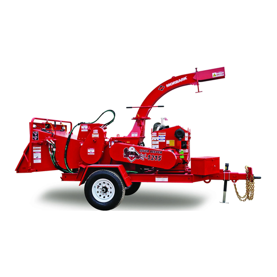
- Page 1 Wood Chipper S/N: 32290 Read this manual before operating the chipper 76347-385 • 10-18...
- Page 2 PLACE MORBARK USB HERE...
- Page 3 All rights reserved. This book is protected by copyright. No part of this book may be reproduced in any form or by any means including photocopying, or utilized by any information storage and retrieval system without written permission from Morbark LLC. Printed in the United States of America.
- Page 4 REVISION LOG Revision: Date Issued: Pages Affected: Description of Changes: Feb. 17 2018 Initial Release Aug 29, 2019 B-4, 13 Fuel and Hyd caps, Bearing Part # WARNING! Item Axle S/N: The engine exhaust from this Engine S/N: product contains chemicals known to the state of California Engine Pump P/N:...
- Page 5 If for any reason you need to correspond with us, or any of the Morbark The five distinct sections are Safety, Chipping Cycle, Features & Function, dealers, please have the serial number handy. It is located on the front Maintenance, and Parts.
- Page 6 Warranty, shall be the repair or replacement of the equipment is normal use and operating conditions subject to the conditions and returned to Morbark’s factory 8507 Winn Road, Winn, Michigan, or at exclusions stated below. No representative, agent, dealer of Morbark, or such other location designated in writing by Morbark.
- Page 7 Use the pink copy and Morbark invoice as a packing slip. Keep the golden rod copy for your records and any future inquiries 2.
- Page 8 Contents Section 1 • Safety ..........1.1 Section 2 •...
- Page 9 Safety Section 1 Symbols, Signs, and Terms..........1.2 General Operator Training .
- Page 10 Safety • Symbols, Signs, and Terms Symbols, Signs, and Terms Warning Symbol Graphics Think Safety Throughout this manual, and on the decals of your machine, you will find Safety is a combination of common sense and alertness at all times when many types of safety symbols.
- Page 11 Safety • General DANGER! Any modification to the machine must be approved by Morbark. Unauthorized modifications to the Figure 1.1 Personal Protection machine may impair the function and/or safety features that could affect machine life or cause serious injury or death to personnel.
- Page 12 • Water tanks and halon gas extinguishers are recommended • Communication device (e.g., cell phone, walkie talkie) • Fully stocked first aid kit. (Can be ordered from Morbark P/N 59135-245) Maintenance • Clean dirt, oil, wood chips, and bark from engine area. Remove debris and accumulated oil, grease, and other flammable material from around the power unit and bearings daily •...
- Page 13 Safety • General Spectators, Children, and Untrained Individuals Handling • Do not allow children or spectators to operate the machine or play • Do not climb, sit, stand, or lay on the machine during operation near the machine during operation •...
- Page 14 Safety • Start-up Checklist Safety Checklist Be sure to check that you have the following items at the beginning of Fuel and oil line connections are securely attached to the fittings and each session or when changing operators: there is no sign of fluid leakage. Tubes and hoses are in good condition Filler caps and drain plugs are securely attached to the machine Emergency equipment on work site: •...
- Page 15 • Each person authorized to lockout the machine must have a safety lock and key dedicated to the machine lockout Morbark chippers are custom built to customer specifications. Control • Authorized personnel must verbally notify affected employees of the panels, power configurations, and other features may differ from each machine lockout, and post a sign(s) indicating the power lockout machine.
- Page 16 Safety • Lockout Procedure • Equipment with main disconnect switches shall be turned off and A. Ensure that the continuity of the lockout procedure locked in the OFF position only after the source of electrical power is is maintained shut off at the point of operational control B.
- Page 17 Safety • Lockout Procedure Safety Lockout Instructions: To Lockout the Yoke: Make sure your chipper is securely attached to a tow vehicle and all Insert the hitch clip into the hole at the end of the yoke locking pin. pressure is off the tongue jack. Check that the hitch clip is securely in place by pulling on the handle Remove jack from tongue, place on jack attachment tube under feed of the yoke locking pin, and attempt to remove it.
- Page 18 Safety • Lockout Procedure To Lockout the drum: Remove the drum locking pin from it’s holder located on the right side of the base. Remove lynch pin, slide the hood locking pin out that holds the drum hood down. Lift the drum hood open. Figure 1.8 Drum locking pin Figure 1.6...
- Page 19 THIS PAGE INTENTIONALLY LEFT BLANK 76347-385 • 10-18 1.11...
- Page 20 Safety • Crime Prevention Crime Prevention • Maintain an inventory record of all equipment and machines. Regularly check to make sure that no machines have been stolen Parking Indoors • Remove the ignition key and place hard-to-move equipment in front of exits It has been proven that thieves are hesitant to take items that can be readily identified.
- Page 21 Anyone working on or around the equipment should be familiar with operator’s manual. DANGER If operators manual is not available, MORBARK will supply a repacement. Failure to Comply May Result in Death or Serious Injury. ADVERTENCIA 39510-215ES CRUSH HAZARD Moving parts, Keep hands clear.
- Page 22 Anyone working on or around the equipment should be familiar with operator’s manual. DANGER If operators manual is not available, MORBARK will supply a repacement. Failure to Comply May Result in Death or Serious Injury. ADVERTENCIA 39510-215ES CRUSH HAZARD Moving parts, Keep hands clear.
- Page 23 ANTES DE UTILIZAR ESTA MÁQUINA. SI SE PIERDEN LOS DOCUMENTOS, COMUNÍQUESE CON NO OPERE CON LA CUBIERTA PROTECTORA UN DISTRIBUIDOR DE MORBARK PARA OBTENER REEMPLAZOS. El incumplimiento puede resultar en la muerte o en una herida grave. ABIERTA. CUMPLA CON TODOS LOS PROCEDIMIENTOS DE BLOQUEO ANTES DE PRESTAR SERVICIO.
- Page 24 Safety • Decal List QR Codes ™ ™ ™ ™ MAINTENANCE MAINTENANCE MAINTENANCE MAINTENANCE MADE EASY MADE EASY MADE EASY MADE EASY MADE EASY MADE EASY MADE EASY MADE EASY AUTOFEED-SETTING KNIFE CARE ANVIL ADJUSTMENT BELT TENSION/ADJUST 39510-331 39510-332 39510-333 39510-334 39510-335 Autofeed Setting...
- Page 25 Safety • Decal List Decal List Part Number Quantity Description 39510-203Es Decal,Danger,Yoke Locks,Eng/Span Combo 39510-204Es Decal,Danger,Thrown Debris,Eng/Span Combo 39510-205Es Decal,Crush Hazard,Hands Clear,Eng/Span Combo 39510-206 Decal,Grease Point 39510-207 Decal,Grease Point 39510-208Es Decal,Safety Gear,Combo 39510-209Es Decal,Notice,Hydraulic Oil,Combo 39510-210Es Decal ,Notice,Clutch Idle,Combo 39510-211Es Decal,Notice,Before Welding,Combo 39510-212Es Decal,Danger,Lock Out Tag Out,Combo...
- Page 26 Safety • Decal List Decal List Con’t Part Number Quantity Description 39510-236Es Decal,Fuel Shutoff,Combo 39510-237Es Decal,Diesel Fuel,Combo 39510-238Es Decal,Hydraulic Oil,Combo 39510-240Es Decal,Cntrl Bar Position,Combo 39510-241Es Decal,Cntrl Bar Position,Combo 39510-242Es Decal,Notice,Oil Shutoff,Combo 39510-248Es Gasoline,Eng/Span Combo 39510-249Es Decal,Danger,Crush Hazard,Eng/Span Combo 39510-250Es Decal,Warning,Raise Infeed Tray 39510-251Es Decal,3/4 Full,Eng/Span Combo 39510-252Es...
- Page 27 The Chipping Cycle Section 2 Preparation Preparation and Set-up ..........2.2 Start-up Fluid Levels.
- Page 28 The Chipping Cycle • Preparation Preparation This section is an overview of the chipping process. It is mandatory that all personnel handling, operating, and maintaining this machine read the manual completely and be properly trained on its use. Operators should also review the manual on a regular basis. Specific information on safety, function, use, and maintenance of a machine feature is also located in the Features and Function section.
- Page 29 The Chipping Cycle • Preparation Brush Preparation Figure 2.1 DANGER! No wider than infeed opening Foreign material (metal, stones, glass) in the chipper will cause damage and potentially shatter the cutting blades resulting in property damage, serious injury, or death. Vines left on the wood may cause entanglement of operating personnel, or hide foreign material resulting in equipment damage, serious injury, or death.
- Page 30 The Chipping Cycle • Preparation Machine Preparation Adjust discharge chute DANGER! Once you have the machine secured and level, the next step in machine preparation is setting up the discharge chute. See page Features and Function section for more detail. Before operating always block the wheels, and ensure the chipper is on stable level ground when not attached to a •...
- Page 31 The Chipping Cycle • Preparation Figure 2.3 Adjust angle of wood chip projection Infeed spout is clear of debris Chipper should sit on a level surface with the machine parallel to the ground Electric brake actuator cable Ball or pintle hitch connection Electrical connection Break-away...
- Page 32 The Chipping Cycle • Start-up Start-up Fluid Levels Before you start the machine it is important to check the fuel, hydraulic oil, and radiator coolant levels. Allow the machine to cool down before adding oil, fuel, or radiator coolant. Remove the cap slowly to relieve pressure. Engine start-up: DANGER! Place the safety control bar into the stop position.
- Page 33 The Chipping Cycle • Start-up After Engine warm-up: Auto Clutch Position the throttle in acceleration mode. Keep it at this speed during the chipping process. Figure 2.6 Figure 2.5 Forward pulls material into Disengage clutch Engage clutch the feed wheels Stop Stop stops movement...
- Page 34 The Chipping Cycle • Chipping Wood Chipping Wood Figure 2.7 Feeding Brush into the Chipper When you are about to feed brush into the chipper, position the throttle at full RPM’s with the safety control bar in the feed position, as discussed on the previous page.
- Page 35 The Chipping Cycle • Shut-down Shut-down Lock-up After the machine is shut-down it is important for safety and security reasons DANGER! to follow the lock-out procedure in the Safety section, page 1.7. The following components must be locked at the end of each work period: •...
- Page 36 The Chipping Cycle • Checklist Now that you’ve become familiar with the entire chipping process, use the checklists below at the beginning and end of each cycle. Checklist Start-up Shut-down Emergency equipment is on the work site Safety control bar is in the stop position At least two trained personnel are on the work site The ignition key is out of the machine and control panel is locked All personal are outfitted with proper protective clothing and gear...
- Page 37 THIS PAGE INTENTIONALLY LEFT BLANK 76347-385 • 10-18 2.11...
- Page 38 Features and Function Section 3 The Basics Right View..............3.2 Left View .
- Page 39 Features and Function • The Basics • Rght View The Basics Figure 3.1 Right View End view Manual swivel discharge handle Feed wheel hydraulic motor Hood locking pin Yoke locking pin Yoke Safety cables Safety control Air filter housing Engine control panel Infeed Engine Clutch and...
- Page 40 Features and Function • The Basics • Rght View Safety control bar Engine control panel Primary controls for the power unit. Controls forward, stop, and reverse action of the feed wheels. Safety cables Engine Provides power to the chipper. Available in a variety of manufacturers and Reverses the feed when the cables are pulled.
- Page 41 Features and Function • The Basics • Left View Left View Figure 3.2 Adjustable deflect Discharge chute Drum locking pin Hydraulic oil gauge and Fuel Tank filler cap gauge and filler cap Hydraulic oil Deflect filter (located handle behind tank) Manual holder Telescoping Tongue...
- Page 42 Features and Function • The Basics • Left View Adjustable deflect Flag holder Easily adjustable discharge deflect with four locking positions. Holds safety clearance flags. Deflect handle Axle Changes the angle of the adjustable deflect. Provides suspension and braking for the chipper. Discharge chute Tire and rims Used to change the direction of the discharge.
- Page 43 Features and Function • Components • Infeed Components Infeed Forward pulls material into the feed wheels Figure 3.3 Stop Stop stops movement stops movement of the feed wheels of the feed wheels Reverse pushes material out of the feed wheels Safety control bar For emergency use only.
- Page 44 Features and Function • Components • Infeed Safety When feeding material into the infeed, keep all body parts outside of the infeed chute. To safely accomplish this the material being fed should be no DANGER! shorter than 4’ long. The brush being fed into the infeed should be no shorter than 4 ft. and no Movement or placement of any part of the body inside the wider than 52”.
- Page 45 Features and Function • Components • Feed Wheels and Chipper Drum Feed Wheels and Chipper Drum Figure 3.4 Discharge chute Knife pocket Chipper drum Top feed wheel Anvil Chipper housing 76347-385 • 10-18...
- Page 46 Features and Function • Components • Feed Wheels and Chipper Drum Safety The feed wheel operates in two directions, forward and reverse. The safety control bar and the emergency cables located on the infeed control the DANGER! direction of the feed wheels. When the chipper drum is moving the chipper hood MUST be closed and Movement or placement of any part of the body inside locked in place using the hood locking pin.
- Page 47 Features and Function • Components • Feed Wheel Drive Feed Wheel Drive Safety DANGER! Moving components will cause serious injury or death. Do not operate without the guards in place. Do not attempt to touch, check, clean, or adjust the chain during operation. Function The feed wheel drive assembly provides power to the top feed wheel.
- Page 48 Features and Function • Components • Yoke Yoke Safety DANGER! Movement or placement of any part of the body inside the yoke will result in mutilation, serious injury, or death. Keep all parts of the body (hands, feet, head) outside of the yoke.
- Page 49 Features and Function • Components • Valve Banks Valve Banks Safety WARNING! Relieve stored hydraulic pressure before performing service to the hydraulic system. Components could be hot to the touch. Function The hydraulic valve bank controls operate the machine. The auto reverse valve stops the feed wheel when low RPM’s are detected from the motor.
- Page 50 THIS PAGE INTENTIONALLY LEFT BLANK 76347-385 • 10-18 3.13...
- Page 51 Features and Function • Components • Discharge Chute Discharge Chute Figure 3.6 Adjustable deflect Discharge chute will rotate a complete 360º Deflect handle adjusts to four angles Discharge chute Transition base Discharge locking pin 76347-385 • 10-18 3.14...
- Page 52 Features and Function • Components • Discharge Chute Safety Function The purpose of the discharge chute is to project chipped wood away from DANGER! the machine and into a designated chipped wood area. Contact with the discharge chute while it’s in motion will The discharge chute has two adjustments to help in discharging the chipped cause serious injury or death.
- Page 53 Features and Function • Components • Discharge Chute Safety To clean out the chute: DANGER! Complete lockout/tagout. Never attempt to remove material by starting the machine and engaging the chipper to blow material out. This is a Inspect to make sure drum/disc has stopped turning. very dangerous and unsafe practice! Pull material out from the open end of the discharge.
- Page 54 THIS PAGE INTENTIONALLY LEFT BLANK 76347-385 • 10-18 3.17...
- Page 55 Features and Function • Components • Hydraulic Oil and Fuel Tank Hydraulic Oil and Fuel Tank Figure 3.7 Hydraulic oil Hydraulic oil filter filler cap Fuel filler cap Hydraulic oil vent cap Sight gauge Sight gauge Inspection cover *Feature varies depending on the model you have ordered, see the options tabs for details on your model. 76347-385 •...
- Page 56 Features and Function • Components • Hydraulic Oil and Fuel Tank Safety Each tank has a filter. The hydraulic oil filter is located on the side of the DANGER! hydraulic oil tank. The fuel filter is locate in the engine enclosure. See your engine operator manual for more detail.
- Page 57 Features and Function • Components • Engine Belt Drive Engine Belt Drive Figure 3.8 Safety Belt guard door for WARNING! checking belt tension Moving belts can cause serious injury or death. Do not operate without the guards in place. Do not attempt to touch, check, clean, or adjust the belts during operation.
- Page 58 THIS PAGE INTENTIONALLY LEFT BLANK 76347-385 • 10-18 3.21...
- Page 59 Features and Function • Components • Engine Engine Figure 3.9 Typical Engine Configuration Right View Left View Air filter Muffler Control panel NOTE: Panel will vary with engine make and Radiator screen model and is shown for (radiator is housed illustrative puposes behind the screen) only...
- Page 60 Features and Function • Components • Engine Safety Function The engine is the source of power for the machine. WARNING! This chipper has many options for its engine. Consult the engine manufacturers manual for the safety, use and maintenance of your specific engine.
- Page 61 Features and Function • Components • Hitch, Chains, and Jack Hitch, Chains, and Jack Figure 3.10 Chipper should sit on a level surface with the machine parallel to the ground Wheel chocks 76347-385 • 10-18 3.24...
- Page 62 Features and Function • Components • Hitch, Chains and Jack Safety When the chipper is attached to a towing vehicle: DANGER! • The towing vehicle must be capable of handling your chipper • Park the vehicle and the chipper on a level surface Before operating always block the wheel, support the tongue and secure the chipper when not attached to a •...
- Page 63 Features and Function • Components • Battery Battery Figure 3.11 Safety WARNING! Battery acid can cause The battery generates severe burns. Wear explosive gas during protective gear when normal operation. handling the battery. Keep ignition sources Battery away at all times. NOTE Charging the battery with cables connected can damage the machines electronic system.
- Page 64 Features and Function • Specifications Model 1215 Specifications Figure 3.12 101” 189” Tank Capacities General Chipper Diesel Fuel ....25.5 gallon Length ..... 189 inches Drum diameter .
- Page 65 Morbark parts and service, the solution to your problems. Buying your parts elsewhere just does not pay. To keep your equipment performing at its peak use GENUINE MORBARK PARTS 800-255-8839 800-832-5618 fax www.morbark.com...
- Page 66 General Maintenance Section 4 Maintenance Overview ............4.2 Air Filter.
- Page 67 General Maintenance • Overview Maintenance Overview Table 4.1 • Routine Maintenance Schedule Start Chipper Component Required Maintenance hours hours hours hours Complete machine Visual inspection (see Safety section) Clean machine Extended Tongue Remove and inspect for cracks along bolt holes, replace if cracks are present Fasteners (except drum knife bolts) Assemble using Loc-Tite 242 (blue) Engine oil...
- Page 68 General Maintenance • Air Filter Air Filter A clean air filter is critical to the performance of the chipper and the life of Inspect the old filter for evidence of dust leakage and gasket sealing the engine. Dirt inside the engine will ruin it. The filter should be problems.
- Page 69 General Maintenance • Lubrication Lubrication Lubricating the machine is vital to its operation. There are many points of lubrication on the machine. These include the wheel axle, feed wheel bearings, yoke cylinder pins, yoke pivot pins, clutch, discharge chute swivel and crank handle, chipper drum bearings, control bar, and battery box. Lubricate the grease points as outlined on the schedule below.
- Page 70 General Maintenance • Lubrication Lubrication Points Discharge Chute Swivel and Crank Figure 4.2 Chipper Drum Bearings Control Bar Yoke Pivot Pin Feed Wheel Bearings Battery Box Clutch Wheel Axle 76347-385 • 10-18...
- Page 71 General Maintenance • Bolts & Torque Bolts & Torque Making sure that all the bolts are regularly checked and tightened to the • Do not use the torque values shown in this chart in place of those specified in other sections of the manual proper torque is critical.
- Page 72 General Maintenance • Bolts & Torque Grade 8 - Coarse Thread Grade 8 - Fine Thread Size Clamp Load Plain Plated Size Clamp Load Plain Plated 1/4-28 (.250) 3,263 14 ft-lb 10 ft-lb 1/4-20 (.250) 2,850 12 ft-lb 9 ft-lb 5/16-24 (.3125) 5,113 27 ft-lb...
- Page 73 General Maintenance • Belt Tension Belt Tension Before adjusting the belt tension: Throttle the engine down and disengage the clutch. DANGER! Shut off the engine, remove the key and conduct machine lockout. Remove the belt guard. Moving belts and chipper drum can pinch body parts, entangle loose clothing, jewelry, and long hair which may If maintenance is required, loosen the engine bolts, remove the belt and fix before setting belt tension.
- Page 74 General Maintenance • Belt Tension Figure 4.4 Figure 4.5 Small 0’ ring Deflection Force Scale Measure the belt span length of the drive, and lay a straight edge across the drive (see Figure 4.4). Set the large rubber O-ring on the body of the tension gauge at the dimension equal to span length (See inset in Figure 4.5).
- Page 75 General Maintenance • Chipper Knives Chipper Knives • Use original Morbark LLC. knives with the correct steel composition and DANGER! hardness. Immediately replace worn knives • Keep the knife edge sharp and anvil square. Use matched sets A rotating chipper drum can pinch body parts, entangle loose clothing, jewelry, and long hair which will result in •...
- Page 76 THIS PAGE INTENTIONALLY LEFT BLANK 76347-385 • 10-18 4.11...
- Page 77 General Maintenance • Chipper Knives To Turn or Replace the Knives: WARNING! Remove the four knife bolts. Clean debris from the knife and knife pocket with a wire brush. Sharp edges and flying debris may cause Inspect the knife holder, knife clamp, knife bolt, and threads for wear or serious injury.
- Page 78 General Maintenance • Chipper Knives To Sharpen the Knife Edge: Place the knife back onto the knife holder. Apply a light coat of anti- seize lubricant to the bolts and clamp. When sharpening the knife edge, use proper grinding techniques (hand file, power belt sander with fine paper, or conventional knife grinder with coolant Slide the knife back (away from the anvil) against the knife bolts.
- Page 79 General Maintenance • Knife Anvil Knife Anvil Before inspecting or maintaining the anvil: DANGER! Raise the yoke and insert locking pin (see Lockout Procedure in Safety Section). Follow steps in Safety Section to shut-down the machine. Failure to lockout the machine (e.g. yoke, shut power off) Figure 4.11 will result in unexpected operation and cause serious injury Rotate jack handle...
- Page 80 General Maintenance • Knife Anvil To Flip or Replace the Anvil: Remove the six anvil bolts. Figure 4.14 Clean debris from the anvil and anvil clamp slots with a wire brush. If the anvil edge is rounded, flip to a new edge or replace. Anvil can be flipped 4 times.
- Page 81 General Maintenance • Chipper Flange Bearing Chipper Flange Bearing Tighten the lock collars onto the flange bearing by driving them in the WARNING! direction the drum is turning (counter clockwise). Remove the allen head screws and drill the shaft enough to seat the Performing maintenance with the power source ON may screws into the shaft (about 1/8 inch), apply Loc-tite to the allen head result in unexpected operation of the machine and may...
- Page 82 General Maintenance • Chipper Flange Bearing Figure 4.15 Washer Bolt B-Loc bushing Chipper drum Chipper drum Chipper drum shaft housing Chipper flange bearing 76347-385 • 10-18 4.17...
- Page 83 General Maintenance • Hydraulics Hydraulics When conducting maintenance on the hydraulic system be cautious of leaks, WARNING! hot components (pumps, motors, relief valves) and stored energy. Always follow safety warnings and procedures when conducting maintenance on the hydraulic system. Hydraulic oil will vaporize and potentially ignite resulting in explosion, fire, and possible serious injury.
- Page 84 General Maintenance • Hydraulics the fluid should be changed. When a dark spot remains in the middle but Troubleshooting the hydraulic system involves talking with the operators, lighter-colored oil migrates outward in the blotter paper, the oil has or is understanding the schematics, and inspection of the machine.
- Page 85 General Maintenance • Hydraulics Table 4.6 • Hydraulic Pump Troubleshooting Guide Symptom Possible Cause Corrective Action Noisy Pump Air in the system Tighten loose fittings. Replace cracked hoses and damaged parts. Maintain hydraulic oil level in tank. Keep 3/4 full. Cavitation (vacuum in pump) Open clogged or restricted intake line or plugged air vent in tank.
- Page 86 THIS PAGE INTENTIONALLY LEFT BLANK 76347-385 • 10-18 4.21...
- Page 87 -40º exists. If you are unsure about the regulations in your area, check with local -40º fire agencies before beginning work. Your Morbark dealer can provide infor- -55º -67º mation about a spark arrestor suitable for use with the power unit installed in this machine.
- Page 88 General Maintenance • Fuel Fuel Fuel Specifications DANGER Use No. 2-D diesel fuel (reference ASTM D975) under normal operating conditions. In extremely cold conditions No. 1-D diesel fuel is recommended. Ignition sources (e.g: lit cigarettes, open flame, sparks, Refer to the engine OEM manual for specific information regarding the type excessive heat) will ignite diesel fuel and result in burns or of fuel to use.
- Page 89 General Maintenance • Tires Tires Figure 4.17 WARNING! Over inflated tires may cause a tire to explode and result in serious injury or death. Always maintain a safe distance Radial Tire away from the tire during inflation. Use a hose with a pressure gauge.
- Page 90 General Maintenance • Troubleshooting Chart Table 4.7 • Chipper Troubleshooting Guide Problem Probable Cause Corrective Action Chipper will not feed properly Dull chipper knives Turn, sharpen, or replace knives Loose belts Check for proper belt tension Knives ground at incorrect angle Grind knives at 31°...
- Page 91 This Page Intentionally Left Blank...
- Page 92 Appendix A ECCENTRIC LOCK COLLAR INSTALLATION PROCEDURE NOTE: It is important to correctly install eccentric lock collars to avoid possible dam- age to components of your machine from occuring. This procedure describes the correct way to install eccentric lock collars on to flange block and/or pillow block bearings.
- Page 93 This Page Intentionally Left Blank...
Need help?
Do you have a question about the EEGER BEEVER 1215 and is the answer not in the manual?
Questions and answers