Advertisement
Quick Links
Electric or I/C
Recommended engine: West 36T2R &Mini pipe
Recommended electric set up: Roxxy
4250/06 800kv Brushless motor & 60A ESC
4s 3200mAh Lipo + 11X10APC E
Recommended servos:
JX HV5921MG rudder and elevator, JX HV6210MG ailerons, JX 4806HB throttle (IC only)
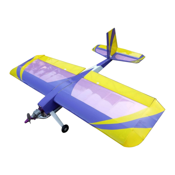
The Cougar 2000 is one of Weston UK`s high performance models now in
performance. Flick the rates on and with the Cougar`s unsurpassable slow
Suitable for electric and IC. Now features open top hatch and two piece wing.
READ THE INSTRUCTIONS FULLY BEFORE COMMENCING
IF UNSURE ABOUT ANY STAGE OF ASSEMBLY PLEASE CONTACT WESTON UK
1x pre cut wing ribs, spars and fuselage formers, 1x undercarriage struts, 1x wing spar,
5x 1/16 balsa sheet, 5x 1/2 x 1/16 balsa strip, 1x 3/16 balsa sheet, 3x 1/4 x 1/8 balsa strip
2x 3mm wheel axle bolts(depending on wheel size), 3x 2mm push rods, 2x swing keepers, 8x clevis links,
5x control horns, 1x closed loop wire and fittings kit, 8x M2 nuts, 4x M3 bolts suitable for an engine mount,
8x M2 bolts suitable for size of control horns, 11x mylar hinges, 6mm od x 4mm id carbon tube,
4x servo wood screw, 2x 12mm x 3mm magnets or 1x canopy catch, 2x M3 nyloc nuts, 2x M3 nuts
kit form designed to provide the ultimate in freestyle and 3D
speed characteristics it becomes the ideal trainer aircraft.
1x 6mm nylon wing bolt, 1x M6 captive nut, 10x M3 captive nut,
2x closed loop wire guide tubes, 2x 6mm hardwood dowel
Required to complete
1x fuel tank (IC package only),
1x engine mount (IC package only), 2x lightweight 2" wheels,
Tools required
Craft knife, thin & thick cyano, sand paper, wet and dry,
sanding block, model aircraft covering (Oracover or Ripmax Aerofilm)
84-88, LONDON ROAD
TEYNHAM,
NEAR SITTINGBOURNE
KENT. ME99QH
ENGLAND
In the Kit
KIT BUILD
Tel:+44(0)1795 521030
Fax:+44(0)1795 522020
www.westonuk.co.uk
Advertisement

Subscribe to Our Youtube Channel
Related Manuals for Weston UK COUGAR 2000


Summary of Contents for Weston UK COUGAR 2000
- Page 1 Recommended servos: JX HV5921MG rudder and elevator, JX HV6210MG ailerons, JX 4806HB throttle (IC only) The Cougar 2000 is one of Weston UK`s high performance models now in kit form designed to provide the ultimate in freestyle and 3D performance. Flick the rates on and with the Cougar`s unsurpassable slow speed characteristics it becomes the ideal trainer aircraft.
- Page 2 Caution: Test fit all parts before final assembly of kit. Some parts may require extra finishing such as sanding. Make sure that you are building on a smooth flat surface. Tools required for building. Craft knife, 30cm minimum steel ruler, set square, wet and dry sand paper, fine round and flat files. Wing assembly To start making the wing you are first going to need to put together the jig provided.
- Page 3 Glue together the two leading edge strips back to back for each wing. Note that the leading edge has a location for wing rib A and the wing tip rib. Dry fit into place and then sand into shape for a symmetrical leading edge. Once the leading edge is in place you can then attach the trailing edge strip.
- Page 4 The wing joiner is made up of four different parts. 2x wing joiner plate and 2x joiner doubler. Glue the doubler onto the wing joiner plate and then insert it into the slot between wing rib A and wing rib B. You must make sure that each doubler is flush with the joiner plate and comes up to the marked line on the joiner plate.
- Page 5 Servo tray sitting flush with 1/16" balsa sheeting Before covering the wing with your choice of covering (Oracover or Ripmax Aerofilm recommended) we suggest taping a piece of string onto the inside of the servo tray and feeding it through the wing and securing onto the outside of the wing rib.
- Page 6 Fuselage assembly When assembling the fuselage it is critical that you dry test fit all the parts before you glue them. This is to make sure all parts fit correctly in the correct place and to make sure that the fuselage does not twist. Some parts may need to be adjusted and cleaned up using files or sand paper.
- Page 7 When satisfied that the floor and the battery tray are in the correct location glue into place using thin cyano. Place into position the floor plate for the open top hatch and then glue into place between fuselage former F1 and F3. Make sure that the hatch bottom sits below the top slot into the firewall.
- Page 8 Joining of fuselage sides Once all parts from fuselage former F1 to F4 are all in place it is time to attach the other side of the fuselage side frame. Making sure that the built up side is on a flat surface, slot into place all the parts in their correct location.
- Page 9 Important: Make sure that TPS and TPB are square and parallel. Any twist is going to offset both the horizontal and vertical stabilisers. Next stage is to temporarily slot into place the rudder and fin. This will help you get the correct location and angle for the rudder closed loop wire guides.
- Page 10 Vertical fin and rudder assembly When starting the rudder, locate both parts labelled fin. You will need to glue these two halves together but first it is recommended that you glue into position three pieces of mylar hinge sandwiched between the two parts. Round off the leading edge of the fin for better aerodynamics.
- Page 11 Tailplane and elevator assembly To start the tailplane assembly, Locate parts TAF, TAC, TAR and 55x4. Attach tail assembly front (TAF) to tail assembly centre (TAC) then tail assembly rear (TAR) to TAC. Attach tailplane tip (TP TIP) to each end of the tailplane assembly and trim to fit if needed.
- Page 12 Tailplane, fin and fuselage assembly Before attaching the complete elevator and rudder assembly to the fuselage make sure that they are both aligned correctly and the vertical fin post is square to the fuselage. Dry fit the complete elevator assembly first and then place the vertical fin and rudder.
- Page 13 Covering removed to attach to fuselage. Complete tail assembly in place Rudder servo installation and closed loop wire assembly Install the rudder servo in the raised servo tray with the output arm rearwards towards F4. The rudder utilizes a closed loop system. Install the 2 x control horns onto the rudder over the reinforced area ensuring the clevis attachment points are over the centre of the rudder hinge line.
- Page 14 Elevator servo installation and push rod assembly Start by atatching the elevator control horn to the underside of the elevator. Make sure that the pivot is exactly inline where the elevator and tailplane is hinged. Note that the control horn is positioned to the left of the fuselage centre line. This is to make sure that the push rod is going to clear the vertical fin post.
- Page 15 Undercarriage Push fit the undercarriage fairings to each undercarriage strut and then secure the wheels into place using an M3 x 40mm bolt, 2x M3 nyloc nuts and 2x M2 washers on each wheel. Use two M3 washers between the wheel then lock into position using an M3 nyloc nut. Be careful not to tighten too much as this will lock the wheel up and not allow it to move freely.
- Page 16 All other engines could be mounted in the same manner using your own engine mount with the cylinder head at the 7 o’clock position. Most standard exhausts can fit in the same way. Weston UK offers Genesis mini pipes for other engines as an alternative silencer.
- Page 17 Electric motor installation The recommended electric power set up for the Cougar is the Roxxy 4250/06 800kv motor and a 60A or higher ESC. For the use of other electric motors there are spacer discs provided in the kit. This will allow you to mount the Roxxy motor or any other motor into a more forward position for more clearance and better balance.
- Page 18 Remember, Before flying check your model thoroughly and do a range check with the engine or electric motor running. Check all electrical connectors are restrained and ensure that the receiver is padded to reduce any vibration. You are responsible for the safe operation of this model. Last of all we wish you many happy hours flying the Cougar 2000 kit.
Need help?
Do you have a question about the COUGAR 2000 and is the answer not in the manual?
Questions and answers