
Related Manuals for CONCORD LULA

Summary of Contents for CONCORD LULA
- Page 1 HORIZON Commercial “LULA” Elevator INSTALLATION and SERVICE MANUAL (To Be Retained by Authorized Concord Dealer) © Concord Elevator Inc. Part # 000532 (Rev. 11/01)
- Page 2 IMPORTANT This Concord Horizon Commercial “Lula” Elevator should be installed, maintained and serviced by authorized CONCORD ELEVATOR dealers only. The authorized CONCORD ELEVATOR dealer should refer to this manual for installation, maintenance, servicing and repairs. The owner is responsible for ensuring the ongoing safe operating condition of the Commercial “Lula”...
- Page 3 CONCORD ELEVATOR INC. CONCORD HORIZON ELEVATOR INSTALLATION AND SERVICE MANUAL TABLE OF CONTENTS PAGE 1 YEAR LIMITED WARRANTY ....................1 INTRODUCTION ........................2 GENERAL SPECIFICATIONS ....................3 TOOLS AND MATERIALS REQUIRED..................4 ELEVATOR TERMINOLOGY ....................5 INSTALLATION SAFETY TIPS ....................7 PRELIMINARY CHECKS......................8 A. PRE-DELIVERY CHECKLIST..................... 8 B.
- Page 4 SETTING THE FLOOR INDICATOR DISPLAY ....ERROR! BOOKMARK NOT DEFINED. MECHANICAL INSTALLATION / FINAL ADJUSTMENTSERROR! BOOKMARK NOT DEFINED. ADJUSTING AND SETTING THE CONCORD EPV VARIABLE SPEED VALVEERROR! BOOKMARK NOT DEF MICROPROCESSOR ............ERROR! BOOKMARK NOT DEFINED. OVER PRESSURE RELIEF VALVE ........ERROR! BOOKMARK NOT DEFINED.
- Page 5 1 YEAR LIMITED WARRANTY Concord Elevator Inc. (herein called “Concord”) warrants to the original purchaser of this product that Concord will repair or exchange, at its option, any parts that fail due to defective material or workmanship as follows: Repair or Replace Parts for a Period of One (1) Year from Date of Installation.
- Page 6 NOTE The Concord HORIZON ELEVATOR is manufactured in the plant according to order dimensions. Any preparatory work such as finishing electric source, pouring concrete base or pit, or carpentry, should be done before the unit is installed.
- Page 7 GENERAL SPECIFICATIONS SPECIFICATION CONCORD HORIZON ELEVATOR Load Capacity 1,400 lbs. (635 kg) Rated Speed 30 feet per minute (0.15 m/s) Power Supply 208 volt, 3 phase or 220 volt, single phase, 30 amps. Drive System 1:2 Cable Hydraulic Cab Size 48"...
- Page 8 • 1/2" Electrical Box Connectors • Shaft Wiring Materials (varies depending on local codes). 20 gauge stranded multi-wire cable with 11 conductors for connection from landings to halfway box (from Concord) NOTE There may be additional tools required to complete your installation.
- Page 9 ELEVATOR TERMINOLOGY TERMINOLOGY DESCRIPTION This is the compartment of the elevator in which people ride. Also, called the car. Cable Hydraulic This is the type of drive system used on the Horizon. It involves a hydraulic jack, wire cable and pulley system to raise and lower the cab compartment.
- Page 10 TERMINOLOGY DESCRIPTION Machine Room This is a separate room usually next to the hoistway to hold the hydraulic power unit and motor control system. Overhead Clearance This is the vertical clearance required to fit the elevator and its drive components at the top floor. It is measured from the upper floor level to top of the hoistway.
- Page 11 THE FOLLOWING SAFETY INSTRUCTIONS SHOULD BE ADHERED TO AT ALL TIMES. PRACTICE SAFETY FIRST. INSTALLATION SAFETY TIPS The following safety installation tips must always be followed. Please read and understand this entire manual before installing the unit and carefully follow all procedures.
- Page 12 PRELIMINARY CHECKS A. PRE-DELIVERY CHECKLIST Carefully check all measurements of the lift hoistway enclosure and compare to the site installation drawing. Main items to be checked are: Checklist 3 Items to be checked against site installation drawing Total travel from the bottom finished floor level to the top finished floor level. Clearance overhead.
- Page 13 INITIAL INSTALLATION PROCEDURES PLACEMENT OF THE POWER UNIT The ideal location for the power unit is to be as close as possible to the hoistway. However, if the installer wants to place the power unit in another location for convenience and/or appearance, then the following must be considered: Do not place the power unit in an area where extreme temperature changes may occur over the year.
- Page 14 LOCAL CODES AND REGULATIONS MAY REQUIRE A LICENSED ELECTRICIAN TO CONNECT TO THE MAINS. CHECK WITH YOUR LOCAL AUTHORITY BEFORE BEGINNING THE WORK. Instruct the electrician as to the proper location for the installation of the following: Install a fused, lockable, disconnect switch with the proper amperage and voltage supply, as detailed on the Pump Unit Data Plate -- or main layout drawing, if provided.
- Page 15 Figure # 2 4 Foot Level Prepared As Template Locate rail brackets and identify the two (2) or three (3) special rail brackets that support the upstand post and jack unit. (These two rail brackets have an angle or threaded rod welded to the inside center).
- Page 16 Starting at the top most rail bracket, begin to install the 90 adjustment angles. (See Figure # 3 and Figure # 4). The face of the 90 adjustment angles is placed 17½ inches from the rail centerline. Once the rails have been installed, a final measurement of 30 inches between rail faces will exist.
- Page 17 13) Ensure that faces of the opposing 90 adjustment angles are square and parallel to each other. 14) Set the pit channel in place with the centerline between rails and center back to front with the center of rails. Leave the pit channel loose but shim it to ensure it is level. Never just “point shim”...
- Page 18 Do not “point file” at the joint. JACK UNIT AND UPSTAND INSTALLATION The heart of the Horizon Commercial “Lula” Elevator is the 1:2 CABLE HYDRAULIC system that drives the lift. This system uses the inherent safety and strength of a hydraulic plunger with the flexibility and ease of cable drive.
- Page 19 The JACK UNIT mounts on top of the UPSTAND POST and the male end of the jacks’ base fits the female socket on the top of the UPSTAND. The UPSTAND fits into the pit channel by mating the male and female ends. Both the UPSTAND POST and the JACK UNIT must be attached to the appropriate attachment bracket on the previously already installed rail brackets.
- Page 20 SPLIT CYLINDER ASSEMBLY Remove any protective cardboard tubes that may have been taped to the exposed ends of the cylinder rod halves. Prepare a lifting device for the raising of the cylinder halves in the hoistway. Lift the bottom half of the cylinder assembly to a vertical position with the exposed plunger facing upwards.
- Page 21 SHEAVE/GUIDE YOKE INSTALLATION The sheave/guide yoke (YOKE) must be installed after the Jack Unit and Upstand Post are assembled and while the scaffolding is still in the shaft. This is a fairly heavy piece. Make sure you have sufficient help to assist in placing the YOKE in position. Use a safety line.
- Page 22 LIFT CHANNEL UPRIGHTS (STILES) AND SLING (See Appendix ‘D’ in this manual for detailed Sling Assembly drawing) The safety blocks are shipped in a small cardboard box. The blocks are covered with a protective coating that must be removed. The best way to remove the coating is by soaking them in a bucket of paint thinner.
- Page 23 Use the hoistway access switch, if supplied, or the manual unlocking device. In compliance with the code requirements, the Concord Car Top Prop can be deployed without full bodily entry into the car top area. The handle of the prop can be reached while leaning out from the landing sill.
- Page 24 NOTE Before entering the car top area or starting to deploy the Prop, set the Car Top Inspection Station Switch from the NORMAL to INSPECT position. THE CAR TOP PROP MUST BE FULLY DEPLOYED TO THE “ON SERVICE” EXTREME RIGHT, ROTATED AND LOCKED POSITION BEFORE ENTERING THE CAR TOP AREA.
- Page 25 CABLE INSTALLATION...
- Page 26 CABLE HYDRAULIC INSTALLATION Make sure the wedge clamps and the eye bolts have been placed in position on the attachment provided near the bottom of the Upstand Post. Identify the cables as they descend the other side of the sheave, and attach them to the wedge clamps.
- Page 27 HYDRAULIC INSTALLATION If a hydraulic hose is being used as the oil supply line to the jack, install a 90 1/2" NPT hydraulic elbow fitting to the oil inlet on the jack. Make sure it points downward toward the Upstand Post.
- Page 28 ALWAYS ADD THE HYDRAULIC OIL TO THE RESERVOIR WHEN THE ELEVATOR IS AT THE BOTTOM. Run the hydraulic line from the pump through the hoistway wall. Ensure that it is well protected from scraping or cutting (a PVC sleeve is recommended). Secure the oil line to the Upstand Post with hose clamps (gear clamps).
- Page 29 Figure # 15 Steel Oil Line Connection to Jack Temporarily wire and connect a set of buttons (located on the end of a 25 foot cord) to the pump unit control box as follows: The UP wire is connected to # 5;...
- Page 30 Power supply is properly connected to the correct voltage and phase. Use your meter to verify. Check that proper fuses have been supplied. On three phase systems, you must confirm that the pump is turning in the proper direction. Jog the pump, and if no pressure appears in the gauge after a few seconds, then reverse any two motor leads on the incoming L1, L2 or L3 power lines.
- Page 31 Particularly, note the sill clearance at each landing, and adjust the platform if necessary. For Concord power sliding doors, the platform sill should be aligned evenly with the landing with a clearance of 7 1/2” (at the tightest point), so that when the landing door is positioned, the sill to sill clearance is 1 1/4”.
- Page 32 This may vary by jurisdiction. Unless otherwise ordered, based on the travel distance supplied with the order, Concord provides 3" of extra travel at the top and 3" of extra travel at the bottom. If the travel is more than 6"...
- Page 33 Use the hoistway access switch, if supplied, or the manual unlocking device and open the lower landing door. In compliance with the code requirements, the Concord Pit Prop can be deployed without full bodily entry into the pit area. The handle of the prop can be reached while leaning into the pit area.
- Page 34 DO NOT ENTER THE PIT AREA UNTIL THE PIT PROP IS SECURELY SET (LOCKED) IN POSITION. SETTING THE SAFETIES Position yourself on the platform and make sure the four lower guide shoes are loose on the bolts. It should be possible to manually push the platform toward the shaft wall and sufficiently open the gap at the back of the safety block to place a 1/16"...
- Page 35 Remove the two shims in place behind the safety blocks before attempting to run the platform any distance. This may be difficult, as they may be “tight” in place and some loosening may be necessary to remove them. Usually, the shims will come out when the elevator is moved in the UP direction and is then lowered.
- Page 36 Locate the cable tensioner assembly and remove the pulley. (See Figure # 22). Figure # 22 Cable Tensioner Assembly Attach the tensioning bar (complete with weight), to the pulley bracket using the 3/8” shoulder bolt supplied. Re-attach the pulley. Block the counterweight up; thereby, lifting the pulley up to its’ highest position. Feed the governor cable through the small hole in the bottom of the governor tripping cage.
- Page 37 11) Take up the excess slack and create a small loop at the end of the cable, insert the thimble then, clamp it together. 12) Insert the cable loop in to the top of the governor tripping cage and secure using clevis pin and cotter pin supplied.
- Page 38 CONNECTING AUX (Auxiliary Contact Switch) - The National Electrical Code requires that when a secondary power supply or battery is used, the main disconnect must be provided with an auxiliary switch that will open when the disconnect switch is opened. This is a safety device and must be provided by the electrical contractor.
- Page 39 Figure # 26 Halfway Junction Box Board...
- Page 40 2 SPEED SLIDING DOORS (See Also Installation Video) Before beginning the installation, ensure that the rough opening is the correct size and that there is adequate support for the entrance. The entrance must attach to masonry, wood studs of sufficient size or heavy steel struts. Drywall and light steel studs are not sufficient support. Also, the elevator must be assembled to a "working platform"...
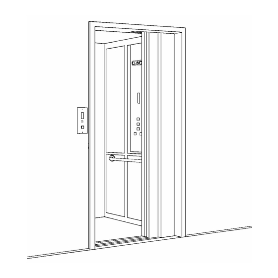
- Page 41 Figure # 27 Landing Door Frame Assembly...
- Page 42 To set the height of the header (Item # 5) from the sill, measure 81" (2057 mm) from the surface of the aluminum sill to the lowest point of the header. See Figure # 28 or # 29. Square up the frame assembly by measuring from corner to corner on both sides and compare the measurements.
- Page 43 Figure # 28 Masonry Door Installation...
- Page 44 Figure # 29 Drywall Door Installation...
- Page 45 Figure # 30 Entrance Frame Attachment...
- Page 46 22) Using a square, set the distance from the outside of the struts to the inside of the strike jamb at 5" (127 mm). See Figure # 28. 23) Tighten the remaining bolt on the strike jamb bracket to the sill. Now go to the top and tighten the 1/4"...
- Page 47 Repeat the same procedure for the top of the entrance assembly, leaving the strut fasteners finger tight. NOTE The entrance assembly may now be plumbed. This is also a good time to re-check all measurements with your documentation. 10) Using a level, roughly plumb the struts and tighten the bottom strut fasteners. 11) Using a plumb line and moving to the top, accurately plumb the entrance assembly in both directions.
- Page 48 Figure # 31 Landing Door Track and Hanger Assemblies...
- Page 49 NOTE 3/8" (10 mm) underneath the door panel is the maximum distance allowed by code. Concord recommends setting the distance at 1/4" (6 mm). 10) Set the slow door in the same manner. Use the edges of the fast door panel for you alignment guide.
- Page 50 Figure # 32 Door Gib Assembly...
- Page 51 For fire and mechanical safety, the codes require additional safety retainers to be installed. Concord provides six (6) safety retainers painted bright red for identification purposes. These retainers must be mounted (one set on the fast door and one set on the slow door), on the underside of the door panels adjacent to the gib assemblies and on the main upper track assembly.
- Page 52 The sill closer is a "handed" device, so holes in the sill have not been pre-drilled. Please refer to Figure # 34 indicating where to drill the holes. Concord has also designed a template to assist in the placement of the holes.
- Page 53 Figure # 33 Sill Closer...
- Page 54 Figure # 34 Door Closure Mounting Instructions Insert the template in the track and slide the template towards the rear until it touches the inside of the frame support upright. Mark the two (2) holes or drill through the template with a 1/4" (6 mm) drill bit. To attach the slow door mounting plate (Figure # 33, Item 4C), measure up from the sill 24"...
- Page 55 The spring tension should be set just enough to close the doors. Don't set it too strong. Installing/Adjusting the Lock The Concord 6940V interlock is a "handed" device so it is important to have the proper hand interlock for each landing.
- Page 56 To position the pick-up rollers to properly mesh with the car door skate, close the door fully and measure from the inside edge of the strike jamb to the edge of the furthest roller. This dimension should be between 9 1/4" - 9 3/8" (235 mm - 238 mm). Note, the rubber door bumpers must be mounted on the strike jamb for this measurement to be correct.
- Page 57 Figure # 37 Aluminum Grip Plate Assembly Figure # 38 Skate Adjustment...
- Page 58 Installing the Emergency Door Key Normally, two emergency unlocking devices are supplied. Typically they are installed in the bottom landing entrance and the next landing above. Some jurisdictions require that unlocking devices be installed on every landing door and some do not permit them at all. Know your local requirements before installation.
- Page 59 Cab Assembly To assemble the cab, proceed as follows: Ensure the handrail is bolted to the control wall. Assemble the cab starting with the control wall first; then the side walls, the slam posts, the opposite wall and finally the car door headers. Install all the 1/4”...
- Page 60 Cab Assembly Type 2 Installing the Door Operator The Concord Model SD door operator has been designed for quick and easy installation and adjustment. It has been factory assembled and tested before shipping. The operator assembly comes complete with the car door contact, door open limit switch, door closed limit switch, gear motor, electronic counter and a hinged enclosure for the electronic controls.
- Page 61 Figure 42 Operator Assembly...
- Page 62 Figure # 43 Operator Assembly...
- Page 63 Figure # 44 Operator Assembly Parts List...
- Page 64 Installing the Cab Doors Loosen the aluminum grip plate (Figure # 37, Item # 1) from the drive belt to allow free movement of the hangers. Install the car doors using the same procedure described for the landing doors. See section called, Installing the Landing Doors.
- Page 65 Interfacing the Car and Landing Doors Now that the car doors are assembled, they need to be interfaced with the landing entrance doors. This is accomplished with the door skate (clutch restraint vane). The skate is the interface between the powered car doors and the unpowered landing doors allowing the door operator to open both.
- Page 66 Figure # 45 Clutch Assembly...
- Page 67 Wiring and Programming the Door Operator There are only a few things that need to be wired and set up for Concord 2 speed doors to be complete. Power and signal wires must be run to the operator from the car top junction box.
- Page 68 NOTE To feed the wiring through the lock nut, start with the 7-wire mascon plug. Turn it on its side and gently push it through the nut. The other wires will slide through easily. In the enclosure, connect the red and black wires for the 27 volt DC supply to terminals T7200 and T7204.
- Page 69 Sequence of operation for Programming the 2 Speed Door Operator P.N. 772073 REV 005 WARNING: After installing the lift and 2 speed doors, the 2 SPEED DOOR OPERATOR functions F8 and F7 must be programmed to ensure proper and safe operation. Until F8 has been programmed the doors do not know where the fully open position is and may slam at full speed into the open-end stop when attempting to reach the fully open position.
- Page 70 TRAVELING CABLES The Traveling Cables exit the back of the Controller Box at the bottom. Route them to the underside of the platform. Attach the Traveling Cables to the underside of the platform using the Under Cab Cable Brackets. (See Figure # 46). Secure the Under Cab Cable Brackets to the bottom of the platform using #10-1/2"...
- Page 71 Figure # 47 Tension Relief Brackets Halfway Box Connections Refer to Appendix A, “Electrical Schematics”, or Figure # 26 (Halfway Junction Box Board). Plug in all the Traveling Cables to their appropriate terminals. Connect nine (9) wires, labelled “to pump”, from the pump to the Halfway Junction Box screw terminals.
- Page 72 OPTO-READERS AND VANES The Series 8000 controller uses the LU, DZ and LD lane on the vanes to determine where the lift stops. Stopping at the floor level occurs when the LU or the LD crosses from the reflective section of the lane to the non-reflective section of the lane. The sequence of operation of the LEDs as they enter and leave the floor vanes is as follows: APPROACHING TOP TERMINAL LANDING...
- Page 73 Figure # 48 4 Stop Cam Arrangement...
- Page 74 Sequence of Operations for LED’s on the Vane (Assumes Traveling UP and Stopping at Top Landing) The binary LEDs enter the vane first and start to decelerate the lift to slow speed. The valve FUNCTION display indicator changes from F3 (UP fast speed) to F1 (UP deceleration) and then to F2 (UP slow speed).
- Page 75 Figure # 49 Infrared Receiver Unit (IRRX) & Bracket SETTING THE FLOOR INDICATOR DISPLAY In order for the car digital display and the lift to operate in the UP direction, the 110 volt power supply must be wired to the appropriate terminals in the pump unit control. See the “Electrical Schematics”...
- Page 76 The heart of the valve is the microprocessor that is provided with software designed and written by Concord. The microprocessor is installed on a PC board mounted to the inside of the door of the pump unit controller. It is factory-programmed with all of the signals that may be required to operate the valve (in accordance with the Order Form).
- Page 77 The Concord EPV Series valves are equipped with an adjustable relief valve that, when set, may be locked and sealed by an inspector. This is also a requirement of most enforcing authorities. As well, it is recommended that the relief valve should be tested and set, even in jurisdictions where an inspection is not required.
- Page 78 PRESSURE GAUGE Every Concord EPV valve is provided with a standard pressure gauge and a pressure gauge isolating valve. It is recommended that the gauge be isolated from the pressure line by turning the gauge isolating valve to “OFF”, unless the lift is being repaired or serviced. To return the gauge to “ZERO”...
- Page 79 On the end of the switch, an adjustable screw can be seen. Turning the screw “IN” or “CLOCKWISE” will increase the pressure at which the contact opens. Turning the screw “OUT” or “COUNTER-CLOCKWISE” will reduce the pressure at which the contact opens. Typically, the contact will open at about 75-100 psi.
- Page 80 DETERMINING SPEEDS In order to facilitate the setting of the speeds for the lift, it is recommended that the technician has an available tachometer. Refer to your contract documents for the rated speed of the lift. Additionally, the technician should have a set of temporary buttons set up and wired, as instructed in the manual.
- Page 81 First, ensure that the vanes or cams have been set at the floor levels, as instructed in the manual. It is recommended that each adjustment be performed in the following order: UP Direction: * Set the UP start time delay. (“F0"...
- Page 82 • Move the TEST/NORMAL switch to the TEST position. Press a control button on the temporary buttons and start the lift. The indicator will illuminate showing a FUNCTION number. While the display is illuminated, press the ONES and TENS buttons at the same time. The display will start to flash. Release the buttons when the flashing starts.
- Page 83 In order to read the pre-set value of F6, press the button marked LEARN and the display will change from “F6” to a number between 1 and 96. The factory default is 50. The indicated number is the value set for the F6 FUNCTION. •...
- Page 84 As the lift approaches the bottom floor, the binary lane on the vane will tell the lift to DECELERATE, as soon as the opto-reader or switch reads the lane or cam. If the deceleration is set too short, the lift will reduce its speed to leveling speed in a rough, jerky manner and remain in leveling speed for excessive time.
- Page 85 NEVER USE OLD OIL! INSTALLATION OF FIRE-RATED PRO-DOORS (OPTIONAL) The Concord HORIZON DOOR LANDING ENTRANCES are fire rated and have been tested and approved for minimum fire separation of two (2) hours. The landing entrances are an integral unit, pre-wired, zinc wipe coated and ready for installation at the site. Each integral landing entrance has a manual or automatic swing type door with a clear opening of 35"...
- Page 86 NOTE: The Series 8000 PRO-LOCK is not compatible with any previous versions. The Concord PRO-LOCK is a true interlock (or elevator style lock). An electric contact will interrupt the power to the control mechanism if the door is in the OPEN position or if the door is not securely closed and locked.
- Page 87 PRO-LOCK Operation With the door in the closed position, the PRO-LOCK is de-energized and the door is locked in the closed position. The latch-bolt is forward into the specially designed doorkeeper. When the latch bolt center pin strikes the uniquely shaped post in the center of the keeper, it allows the silver-plated electrical contacts within the PRO-LOCK to close.
- Page 88 Figure # 53 PRO-LOCK...
- Page 89 ELECTRICAL CONTACTS ADJUSTMENT Observe the two electrical contacts on the carrier mounted on top of the latch bolt. When the latch bolt is fully forward into the keeper, there should be at least 1/16" of spring compression on each side of the contact. This indicates sufficient contact pressure to permit consistent electrical operation.
- Page 90 NOTE Watch for the operator heat sink and operator card, DO NOT LIFT ON THIS SECTION! Once the operator is clear of the frame, it may be placed on a flat surface with the limit PC board facing up. NOTE The main PC board may rest on the flat surface.
- Page 91 Remove the motor armature lead/plug (red and black wire, 18 gauge, and cut the two leads about 2" - 3" from the plug. Strip the wire ends and connect them back together reversed (i.e. red to black and black to red). Connect with wire nuts or other suitable connector, do not simply tape them together.
- Page 92 Figure # 55 Power Door Spring To Pre-Load the Spring NOTE Have a 6" long bladed, narrow, flat screwdriver available. Grasp the roller at position A and rotate to position B. The spring will create a large amount of back pressure, DO NOT RELEASE ARM, or it will return to near position A. With the arm held in position B, insert the screwdriver between the chain links of the large (#50) chain, the upper chain, and ensure that it goes through to the chain on the other side.
- Page 93 To replace the arm into the operator drive shaft, move the door back and forth slowly. The pin end of the arm will rotate, making it easier for insertion. Line up the placement marks made earlier on the drive shaft and pin coupling. Replace the 1/4" - 2" screw and tighten. In order to release the spring tension, push the door open slightly and the arm and spring will start to rotate, as will the drive chains which are being held by the screwdriver.
- Page 94 AUTOMATIC SWING DOOR (OPTIONAL) With the door closed, the OL + 12V LEDs should be on. With the door opened, OL + 12V are on all the time, ME + OP + OPA come on as soon as the door starts to open, RESET comes on for about 3 seconds, and CL comes on once the door opens 1/2”.
- Page 95 SERVICING THE CABLE HYDRAULIC ELEVATOR CYLINDERS The cylinders have been designed with simplicity in mind and have a small number of moving parts that may have potential for failure. These elevator cylinders will give the user thousands of cycles under normal use if the elevator cylinder has been correctly installed, the hydraulic system pressure has been correctly set, the hydraulic oil is of the correct type, and most of all, is clean and free of contaminants.
- Page 96 Install the new U-Cup Rod Seal (Item # 6) into its corresponding groove. Be sure that the lips of the U-Cup Rod Seal are facing down or toward the cylinder casing. Fit the Rod Wiper (Item # 5) into the final groove at the top of the Gland Cap. (Twisting the seal to a figure 8 shape will assist the installation of the seal).
- Page 97 Figure # 58 Hydraulic Cylinder...
- Page 98 TROUBLESHOOTING GUIDE ALWAYS DISCONNECT ALL ELECTRICAL POWER TO THE ELEVATOR BEFORE ATTEMPTING TO REMOVE OR ATTACH ANY CONNECTIONS, PC BOARDS OR FUSES. NOTES: Ensure all the green LEDs in the car controller are ON at all times. Ensure that the yellow RDC LED located on the bottom board in the car controller (OUTPUT board) is NOT ON.
- Page 99 CONDITION PROBABLE CAUSE(S) Elevator travels in DOWN a) Valve operator board not adjusted properly direction very slowly b) Elevator binding on rails / improper lubrication c) Rails not plumb d) Gate valve partially closed e) Jack is binding f) Proportional valve faulty g) Valve microprocessor faulty h) Flow control (if equipped) faulty or not set Fuses at disconnect blown...
- Page 100 TESTING OPERATION The following features must be verified as operational before the elevator can be released to the customer. TO AVOID PERSONAL INJURY, NEVER STAND DIRECTLY UNDER THE CAB OR INSIDE THE HOISTWAY DURING TESTING. Cab Key Switch Verify that when the key is in the OFF position, the buttons on the cab station are inoperable.
- Page 101 BEFORE LEAVING THE JOB SITE Clean up the work area. Make sure all anchoring bolts/nuts are securely tightened (ie. rail brackets, rail joints, carriage, pump unit, and cab bolts/screws). Make sure all controls operate as outlined in “Testing Operation” section of this manual. Demonstrate the operation of the elevator.
- Page 102 APPENDIX ‘A’ Electrical Schematics NOTE These electrical schematics are a simplified version for the HORIZON Elevator. The exact schematics for the HORIZON Elevator are shipped with the unit and may be different from what is shown in Appendix A. For accuracy, only the schematics shipped with the lift should be used.
- Page 103 Index of Schematics DESCRIPTION PAGE Floor LEDs when ready to accept a call ..............Power Supply - Series 8000 ..................... Keyswitch Wiring Diagram - Series 8000 ................. Photo Eye Terminal Board - Series 8000 ................. Hall Call Wiring - Manual Swing Door with Smart Pro-Lock - Series 8000 ....... Hall Call Wiring - 2 Speed Sliding Door ................
- Page 119 Proportional Valve Control Overview Switches: Test / Normal Buttons: Tens, Ones, Learn, and Store Normal Operation: Display will change to show the function while in use. It will display what is currently happening as the lift moves from floor to floor. It will blank when the lift is not moving. Test Operation: Valve will operate as in normal operation in both function and display until it is put into the program mode.
- Page 120 SERIES 8000 LED AND RELAY FUNCTION GUIDE...
- Page 121 SERIES 8000 BOARD RELAY FUNCTION POWER SUPPLY +30VAC LED2 GREEN, AC OUTPUT FROM TRANSFORMER. (772039) SHEET 1 +27VDC LED4 GREEN, RECTIFIED, UNREGULATED SUPPLY. LED3 YELLOW, ON WHEN FUSE IS BLOWN. LIGHT SUPPLY GREEN, 27VAC LIGHTING SUPPLY LED1 OVERLOAD YELLOW, ON WHEN MWTC OR OL1 OPEN. LED6 DOWN VALVE RED ON WHEN DOWN SIGNAL PRESENT.
- Page 122 SERIES 8000 BOARD RELAY FUNCTION SHEET 11 LED906 RED, DOORS CLOSED AND LOCKED (DCL) RELAY INDICATOR. ON WHEN ALL DOORS ARE CLOSED AND LOCKED. SWITCHES SUPPLY FOR UP AND DOWN SIGNALS AND POWER TO PUMP UNIT. DCL1 AUXILLIARY TO DCL RELAY. SHEET 11 LED907 RED, UP/DOWN AUXILLIARY (UDA) RELAY INDICATOR.
- Page 123 SERIES 8000 BOARD RELAY FUNCTION SHEET 12 LED921 YELLOW, REDUNDANCY CHECKING. ON WHEN FAILURE DETECTED. REMOVES SUPPLY FOR UP AND DOWN SIGNALS WHEN FAILURE DETECTED. LOGIC (772013) LED801 GREEN, REGULATED 5V ON LOGIC. SHEET 5 TIMER (772017) ET/NI LED702 RED, ENTRANCE TIMER/NON-INTERFERENCE (ET/NI) SHEET 7 RELAY INDICATOR.
- Page 124 SERIES 8000 BOARD RELAY FUNCTION SUPPLIES POWER FOR SFC RELAY. LED406 RED, REAR CALL (RC) RELAY INDICATOR. ON WHEN CALL PRESENT. SUPPLIES POWER FOR SRC RELAY. LIMIT LED411 RED, FLOOR LIMIT (LIMIT) RELAY INDICATOR. ON WHEN AT FLOOR AND “S” SIGNAL PRESENT OR WHEN AT APPROPRIATE TERMINAL LIMIT SWITCH.
- Page 125 SERIES 8000 BOARD RELAY FUNCTION SHEET 50 27VDC RED, +27VDC REGULATED SUPPLY IS PRESENT. LED1201 SHEET 51 12VDC RED, +12VDC REGULATED SUPPLY IS PRESENT. LED1208 SHEET 50 RE-OPEN RED, RE-OPEN. PULSED WHEN OVER CURRENT IS LED1204 DETECTED. STOPS CLOSING FUNCTION AND RE-CYCLES GATE OPEN OPEN.
- Page 126 SERIES 8000 BOARD RELAY FUNCTION SHEET 43 SUPPLIES OPEN SIGNAL FOR FRONT SLIDING DOOR. LED9 RED, DOOR OPEN REAR (DOR) RELAY INDICATOR. ON WHEN DOORS NOT FULLY OPEN AND IN OPENNING CYCLE. SUPPLIES OPEN SIGNAL FOR REAR SLIDING DOOR. RED, DOOR OPEN LIMIT FRONT (DOLF) RELAY INDICATOR. DOLF LED13 ON WHEN FRONT DOOR NOT FULLY OPEN.
- Page 127 SERIES 8000 BOARD RELAY FUNCTION HLCALL RED, HOME LANDING CALL (HLCALL) RELAY LED5105 INDICATOR. ON WHEN HOME LANDING CALL IS PLACED. HLCAL PLACES CALL TO CUSTOMER SELECTED LANDING WHEN TIMER TRIPS. CTIS (772009) LED990 RED, INSPECTION (INS) RELAY INDICATOR. ON WHEN SHEET 12.4 LIFT IS NOT ON INSPECTION.
- Page 128 SERIES 8000 BOARD RELAY FUNCTION UDA1 REMOVES AVAILABILITY OF LOCK SUPPLY WHILE TRAVELLING BETWEEN FLOORS. LED3 RED, IN USE (IU) RELAY INDICATOR. ON WHEN DOORS OR GATE OPEN OR KEY SWITCH IS ON. WHEN ENABLED, TURNS ON HALL BUTTONS DURING IN USE.
- Page 129 JUMPER SELECTION GUIDE...
- Page 130 CONCORD SLIDING DOORS. CONFIGURES CONTROLLER FOR OPERATION WITH CONCORD POWER SLIDING DOORS ONLY. GATE/SWING DOOR J801 DOL SELECT. USED WITH CONCORD POWER DOORS ONLY. USED IN CONJUNCTION CONTROLLER WITH J300 (2-3) ON MOTHERBOARD. ALWAYS DISABLED WHEN CONTROLLER CARD (772003) USED TO CONTROL GATES ONLY.
- Page 131 KWIK. CONTINUOUSLY MAINTAINS LOCK SUPPLY TO HALL STATION WHILE AT FLOOR. KWIK J404 (2-3) CONCORD POWER DOORS. MAINTAINS LOCK SUPPLY TO HALL STATION ONLY WHILE DOOR IS NOT CLOSED. J405 FRONT SELECT. ENABLES USE OF SFC RELAY. CAN BE USED FOR KEYED ACCESS FOR LOCKOUT.
- Page 132 SERIES 8000 JUMPER FUNCTION OPEN=DISABLE SHORTED=ENABLE SHORT TO OBTAIN LISTED FUNCTION BOARD J4304 FLOOR 1 PRO LOCK WITH MANUAL DOORS. USED IN CONJUNCTION WITH J4303. J4305 (1-2) FLOOR 2 KWIK LOCK. SWITCHES DOOR MONITOR OFF WHEN SECOND FLOOR DOOR IS OPEN.
- Page 133 J701 J702 J703 J704 J705 J706 J707 TIMER BD. (772017) JUMPER FUNCTIONS SCHEMATIC SHEETS 7-8 o---o J701. CAR KEY SWITCH TURNS ON ET/NI AND INUSE. o---o J702. CAR KEY SWITCH TURNS OFF CAR BUTTON CONTROL WHEN KEY SWITCH IS OFF. o---o J703.
- Page 134 APPENDIX ‘B’ Troubleshooting Via The Sequence of Operations...
- Page 135 OPTO READER Ref Sheet 17 Part Number - 772027 NOTES Doors Closed - Lift Levelling Down in to Floor ST causes the hall and landing Displays to change and makes the circuit for S on the floor Card. When Lift Arrives at Floor travelling down, the lift will stop at its destination Door Opening floor when the LD LED goes off.
- Page 136 APPENDIX ‘C’ Sample Shop Drawings...
Need help?
Do you have a question about the LULA and is the answer not in the manual?
Questions and answers