
Related Manuals for Midea Hybrid Series


Summary of Contents for Midea Hybrid Series
- Page 1 Hybrid Solar Inverter User Manual For three phase inverter Thank you for purchasing our product. Before using the unit, please read this manual carefully and keep it for future reference.
- Page 2 DECLARATION The right to modify the frame dimensions, functionality, technical data, parameters, standards without prior notice are reserved. The contents of this manual have been checked for accuracy with its described hardware and software. However, the contents of this manual may be subject to appropriate modification as a result of product upgrades, specification changes, and updates of the manual, we cannot guarantee full accordance all the time.
- Page 3 CONTENTS 1 Safety Precautions -----------------------------------------------------------------------------------------------01 1.1 Important Safety Instructions --------------------------------------------------------------------------------01 1.2 Important Safety Instructions --------------------------------------------------------------------------------05 1.3 CE Directives ----------------------------------------------------------------------------------------------------06 2 Introduction -------------------------------------------------------------------------------------------------------07 2.1 Model Description ----------------------------------------------------------------------------------------------07 2.2 Basic features ---------------------------------------------------------------------------------------------------07 2.3 Work Modes ----------------------------------------------------------------------------------------------------09 2.4 Dimensions ------------------------------------------------------------------------------------------------------12 2.5 Terminals ---------------------------------------------------------------------------------------------------------12 2.6 Parameters ------------------------------------------------------------------------------------------------------13 3 Installation ---------------------------------------------------------------------------------------------------------16 3.1 Check for Physical Damage --------------------------------------------------------------------------------16...
- Page 4 1 Safety Precautions Safety signs in this manual: DANGER indicates high-risk potential hazards that, if not avoided, may lead to death or serious injury. DANGER WARNING indicates moderate-risk potential hazards that, if not avoided, may lead to death or serious injury. WARNING CAUTION indicates low-risk potential hazards that, if not avoided, may lead to minor or...
- Page 5 Before attempting any maintenance, cleaning or working on any circuits connected to inverter, authorized service personnel must disconnect both AC and DC power from WARNING inverter. Do not operate the inverter while the equipment is running. WARNING Risk of electric shock! WARNING •...
- Page 6 The islanding effect is a special phenomenon where a grid-connected PV system still delivers power to the nearby grid when voltage losses occur in the power system. This can be dangerous for maintenance personnel and the public.The Midea series inverters offer Active Frequency Drift (AFD) to prevent the islanding effect.
- Page 7 1.1.3 PE Connection and Leakage Current • The end-use application shall monitor the protective conductor by residual current operated protective device (RCD) with rated fault current Ifn≤240mA which automatically disconnects the device in case of a fault.The device is intended to connect to a PV generator with a capacitance limit of about 700nf.
- Page 8 1.1.6 Battery Safety Instructions Midea hybrid Series inverter should be used with low voltage battery, for the specific parameters such as battery type, nominal voltage and nominal capacity etc., please refer to section 4. As accumulator batteries may pose risks of electric shock and short-circuit current danger, to...
- Page 9 1.3 CE Directives This chapter follows the requirements of the European Low Voltage Directive, which contains safety instructions and conditions of acceptance for imported systems that you must follow when installing, operating and servicing the equipment. If ignored, it may result in personal injury or death, or damage to the equipment.
- Page 10 H: Battery high voltage 2.2 Basic features Midea Hybrid Series is a high performance inverter that converts solar energy to DC power and stores the energy in batteries. The inverter can be used to optimize its own energy consumption, to store energy in batteries for future use or to connect to the public grid.
- Page 11 I-Version applies to wiring rules that require that the N (neutral) wire of other power sources must not be isolated or switched (applicable to Australian and New Zealand wiring rules AS/NZS_3000:2012). I-Version system diagram N BAR Link Normal Loads PE BAR The grounding screw hole of inverter is at the lower right corner.
- Page 12 2.3 Work Modes The inverter offers multiple working modes according to different requirements. Work mode: Self-use I. When PV, Grid, Battery is available: Solar energy provides power to the loads as first priority. If solar GRID energy is sufficient to power all connected loads, the excess solar energy will be used to charge the battery, and the reduntant power will be used to feed the grid.
- Page 13 III. When PV, Battery is available (Grid is disconnected): Solar energy provides power to the loads as first priority. If solar energy is sufficient to power all connected loads, solar energy will provides to charge battery. Solar energy provides power to the loads as first priority. If solar energy is not sufficient to power all connected loads, battery energy and solar energy will supply power to the loads at the same time.
- Page 14 II. When Grid.Battery is available(PV is disconnected): On charge time, grid will charge battery and supply power to the GRID connected loads at the same time. On discharge time,if load power is less than battery power, battery GRID will supply power to loads as first priority. The excess power will be feed to grid.
- Page 15 2.4 Dimensions ME-HT6H, ME-HT8H , ME-HT10H , ME-HT12H , ME-HT15H Mounting hole dia. Unit, mm Terminals PV1+ PV string 1 positive input PV String Input BAT Port PV1- PV string 1 negative input PV2+ PV string 2 positive input COM1 PV2- PV string 2 negative input PV1+...
- Page 16 GRID (Diesel generator function is unreleased currently) Backup 1 Grid line A phase Backup1 line A phase Grid line B phase Backup1 line B phase Grid line C phase Backup1 line C phase Grid line null line Backup1 line null line Grid line ground electrode Backup1 line ground electrode Backup 2...
- Page 17 AC input Model ME-HT6H ME-HT8H ME-HT10H ME-HT12H ME-HT15H Rated grid voltage 3W+N+PE, 220 / 380 V; 230 / 400 V; 240 / 415 V Rated grid frequency 50Hz / 60Hz Rated active power 12 kW 16 kW 20 kW 24 kW 30 kW Max.
- Page 18 Safety protection Model ME-HT6H ME-HT8H ME-HT10H ME-HT12H ME-HT15H DC-side disconnection device ○ PV string reverse polarity protection ○ All-pole sensitive residual current monitoring unit ○ Anti-islanding protection ○ AC output over current protection ○ AC output short circuit current protection ○...
- Page 19 3 Installation 3.1 Check for Physical Damage Make sure that the inverter is intact during shipment. If there is any visible damage, such as cracks, please contact your dealer immediately. 3.2 Packing List Open the package and take out the product, please check the accessories first. The pack- age list is shown below.
- Page 20 3.3 Mounting 3.3.1 Installation Precaution Midea Series inverter is designed for outdoor installation (IP 65). Please ensure that the installation location meets the following conditions: • Not in direct sunlight. • Not in areas where highly flammable materials are stored.
- Page 21 3.3.2 Space Requirement • Space Requirement Directions BOTTOM LEFT RIGHT FRONT Min. size (mm) 3.3.3 Installation Procedure Tools: Terminal blocks, RJ45 crimping pliers, screwdrivers, hand wrenches and drills, etc. Step 1: Mounting the wall bracket on the wall 1. Place the bracket on the wall, mark the location of the six holes and then remove it. 2.
- Page 22 Step 2: Use the screws to fix the crossbar as shown in the figure below. Step 3: Place the inverter on the wall-mounted bracket by holding the handle on the side. Step 4: Tighten the fixing screws on both sides of the inverter. Step 4 Step 5: If necessary, an anti-theft lock can be installed on the lower left side of the inverter.
- Page 23 4 Electrical Connection 4.1 PV connection Hybrid Inverter can be connected in series with 2-strings PV modules for 6KW,8KW,10KW,12KW. Select PV modules with excellent function and reliable quality. The open-circuit voltage of module arrays connected in series should be less than Max. DC input voltage. Operating voltage should be in accordance with MPPT voltage range.
- Page 24 Plug the PV connector into the corresponding interface on the inverter. 4.2 Grid connection The Midea series inverters are designed for three-phase grids. The voltage is 380/400/415V and the frequency is 50/60Hz. Other technical requirements should be in accordance with the requirements of the local public grid.
- Page 25 Connection steps: Step 1: Check the grid voltage. 1. Check the grid voltage and compare it with the allowed voltage range (Refer to technical data). 2. Disconnect the board from all phases and ensure that it is not reconnected. Step 2: Remove the waterproof lid from the grid port on the inverter.
- Page 26 AC port when the grid is on and through the EPS port when the grid is off. I Version & E Version Midea series inverter provides two versions for customer to choose based on the local rules. Version I applies to wiring rules that require EPS load-side ground to be isolated from grid-side...
- Page 27 E-Version system diagram Normal Loads PE BAR The grounding screw hole of inverter is at the lower right corner. I-Version system diagram N BAR Link Normal Loads PE BAR The grounding screw hole of inverter is at the lower right corner. * If you have a request for a compatible contactor, please contact our sales.
- Page 28 The Midea series hybrid inverters have grid-on and grid-off functions. When the grid is on, the inverter will output power through the AC port, while when the grid is off, it will output power through the BACKUP ports.
- Page 29 10mm Insert & Crimp To: BACK-UP 1 10mm Insert & Crimp To: BACK-UP 2 Requirements for EPS loads Make sure the rated load power of the EPS is within its rated output range, otherwise the WARNING inverter will shut down with an "overload" warning. When an "overload"...
- Page 30 300VA (W) Fridge: 150W 4.4 Battery Connection The charge/discharge system of Midea series hybrid inverters is designed for high voltage lithium batteries. Before selecting a battery, please note that the battery communication should be compatible with the Midea series hybrid inverter.
- Page 31 Recommended non-polar DC breaker-breaker Model ME-HT6H ME-HT8H ME-HT10H ME-HT12H ME-HT15H Nominal voltage of DC breaker should be larger than Voltage maximum voltage of battery Current (A) Battery connection diagram Battery connection BATTERY BMS PIN Defination The communication interface between the inverter and the battery is RJ45, and its protocol is RS485 or CAN.
- Page 32 15mm Insert & Crimp 4.5 CT Connection and Phase instruction CT is used for monitoring the power usage for entire house, at the meantime, inverter will also need the data from Meter to achieve the Export Control Function. CT connection and phase wiring diagram •...
- Page 33 CT connection steps: Step 1: Disassembly of waterproof connector and waterproof cover. Step 2: Prepare a communication cable (without sheath) and pass the cable through the waterproof connector. Step 3: Insert RJ45 end of the CT cable into the CT port of the inverter. Step 4: Assemble waterproof connectors and waterproof cover..
- Page 34 4.8 GPRS Connection (optional) Midea hybrid inverters offer a GPRS (radio frequency) interface to control the switching time of a given load via a smart plug (which can be purchased from the supplier if required), thus allowing the load to consume mainly PV energy during operation and minimizing energy costs.
- Page 35 4.9 Inverter Manipulation Start inverter after checking all the following steps: Make sure the inverter is fixed well on the wall. Make sure all DC wiring and AC wiring is complete. Make sure the meter/CT is well connected. Make sure the battery is well connected. Make sure the external load contactor is well connected.
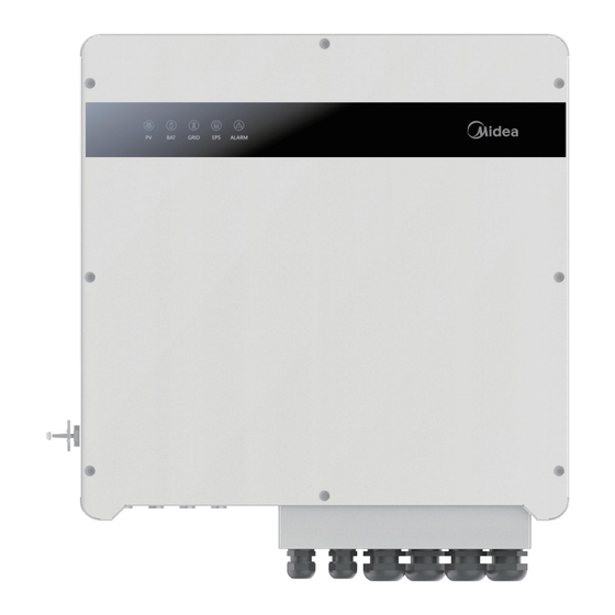
- Page 36 5 Setting 5.1 LED Panel Instructions for LED Indicator LED Indicator Status Description PV input is normal. PV is unavailable. Battery is active. Battery is unavailable. GRID is available and normal. GRID GRID is unavailable. GRID EPS power is available. EPS power is unavailable.
- Page 37 Open the APP and go to the main interface of the APP. Click "Local Mode", make sure your Bluetooth is enabled, scan the QR code on the collector or manually enter the serial number to connect to the collector. After the connection is successful, the COM indicator is steady on and the READY indicator is blinking.
- Page 38 5.2.2 Display interface 5.2.2.1 Solar page Real-time parameters about the PV. This page shows the voltage and current, power, and energy parameters on the DC side. ・ Dc voltage : PV input real-time voltage. ・ Dc current : PV input real-time current. ・...
- Page 39 5.2.2.3 Battery page Real-time parameters about the battery. ・ Battery type : (lead-acid, lithium battery, DC-SOURCE). ・ Battery Voltage : Battery real-time voltage. ・ Battery Current : Battery real-time current. ・ Battery Power : Charge power. “ + ”means charge, “ - ” means discharge.
- Page 40 5.2.2.5 Other page Some information from inverter. ・ Power Level : This interface show inverter model, for example 5.0kW,8.0kW. ・ Inverter State : Displays the inverter status information ( INIT, STANDBY, PV GRID,BAT GRID, HYBRID POW, AC BAT CHG, PV BAT CHG, BYP, FAULT). ・...
- Page 41 5.2.2.7 BMS page This screen displays the alarm code obtained by the BMS when an inverter alarm is generated. 5.2.2.8 GEN page This screen displays the input voltage frequency, voltage, current, and power parameters of the generator. 5.2.2.9 DEBUG page Special debugging instruction code.
- Page 42 5.2.2.10 Home Load page The home load parameter takes effect only when the home load is connected. 5.2.2.11 Parallel 3Phase page Group three - phase parameter interface, available only when the three - phase is enabled. If you need to use, please consult local dealers.
- Page 43 5.2.3 APP Parameter setting page 5.2.3.1 Grid settings You need to enter a password to access the grid Settings screen. The default password is 00000. ・ Grid Std : This interface is used to select Grid standard. (see 5.2.3.1.1) ・ Vac Min : The input value of Grid low voltage. ( This is valid only if the grid standard is ”custom”) ・...
- Page 44 5.2.3.2 Battery set ・ DisChg Power Scale : The input value is power percent of battery discharge. The default value is 100%. ・ Bat On-Grid DOD : The depth of battery discharge when connected to the grid. When the battery discharge exceeds the DOD parameter, the inverter generates a low voltage or under voltage alarm, and the battery stops discharging.
- Page 45 5.2.3.3 Battery Energy Management-Custom model available This function only applies to some models, please consult the corresponding supplier whether it can be used. 5.2.3.4 Grid Protect Set Customers do not need to change the Grid protection Settings. If any modification is required, consult the local supplier. 5.2.3.5 Battery 485 communication parameter ・...
- Page 46 5.2.3.6 Active control ・ Generation voltage response : When the grid voltage is abnormal, the active power is limited, and the function is enabled when required by the national grid standard. ・ Generation frequency response : When the power grid frequency is abnormal, the active power will be limited, and the function will be enabled if required by the national power grid standard.
- Page 47 5.2.3.7 Setup ・ Work Mode : This interface is used to select the working mode, includes SELFCONSUME, PEAK SHIFT, BAT PRIORITY. The default setting is SELFCONSUME. ・ Input Mode : Setup of PV Input mode ( INDEPENDENT : The default Settings, PARALLEL : This feature is for test use only, not customer use, CV : This feature is for test use only, not customeruse ) .The default setting is Independent.
- Page 48 5.2.3.9 Peakshift This time range is enabled only when the working mode is Peak shift. ・ Peak shift : This function allows three charge and discharge cycles to be set to ensure that the inverter's time is local when the time is set. This parameter is set to one day, if the specified time conflict, the first time is executed as the master time;...
- Page 49 5.2.3.11 Generator Set This page is the generator settings, and you can modify the parameters of this section through this page ・ GEN Enable : Enable control of the Generator function. ・ GEN Charge Enable : Generator Charge Enable control. ・...
- Page 50 5.2.3.12 Advance Work Mode Set ・ Advanced mode work : There are three advanced modes available: Sell First, limit grid consumption, zero export. The Basic mode feature is automatically disabled when you enable Advanced mode. ①Sell First : First consider selling electricity to the grid. In this mode the anti-reflux setting is automatically disabled.
- Page 51 5.2.3.12 Advance Work Mode Set ・ Slot1 Gen Charge Enable : Gen charging is allowed in Slot1. There are 6 slots which can be programmed. You can set the advanced mode first, and then set the battery to charge or discharge in the set time, choose grid charge or generator charge. The following functions do not need to be configured.
- Page 52 6 Fault diagnosis and solutions The following table li`sts some basic problems that may occur in practice and the corresponding basic solutions. When you encounter the following problems, please refer to the following solutions. • If the problem is still not solved, please contact your local distributor. •...
- Page 53 Codes: Solutions: Bat Under Vol Content: • Checking system settings, re-power and restart. Explaination: • Check if the grid power down. If so, waitting for Battery voltage lower than normal range. the grid power up, the inverter will automatically charge. •...
- Page 54 Codes: Solutions: Gfci over Content: • Check PV string for direct or indirect grounding Explaination: phenomenon. Inverter GFCI exceeds standard. • Check peripherals of inverter for current leakage. • If the error/warning remains, please contact customer service. Codes: Solutions: Bus under vol Content: •...
- Page 55 Solutions: Codes: 18 / 19 Inv under vol / over vol Content: • Check if the INV voltage is abnormal. Explaination: • Restart the inverter and wait until it functions INV voltage is abnormal. normally. • If the error/warning remains, please contact customer service.
- Page 56 Codes: Codes: Solutions: The battery cell pressure difference Content: • Check whether the battery cell voltage difference is large is too large. Explaination: BMS monomer differential pressure alarm. Codes: Codes: Solutions: Bat reverse connection Content: • Detect whether the positive and negative poles of Explaination: the battery are connected reversely.
- Page 57 Codes: Solutions: Arc Fault Content: • Check Photovoltaic panels, PV wire. Explaination: • If the error/warning remains, please contact PV Arc Fault customer service. Codes: 32 / 33 Solutions: Bus soft fail / Inv soft fail Content: • Restart the inverter and wait until it functions Explaination: normally.
- Page 58 Codes: Solutions: Grid Relay Fault Content: • Restart the inverter and wait until it functions Explaination: normally. The inverter may be damaged. • If the error/warning remains, please contact customer service. Codes: Solutions: EPS rly fault Content: • Restart the inverter and wait until it functions Explaination: normally.
- Page 59 Codes: The copy right of this manual belongs to GD Midea Heating & Ventilating Equipment Co., Ltd. Any corporation or individual should not plagiarize, copy, reduction, or distribution this manual in any form or by any means. All rights reserved.
- Page 60 V1.0 Fault diagnosis and solutions...
Need help?
Do you have a question about the Hybrid Series and is the answer not in the manual?
Questions and answers