
Related Manuals for Gigabyte XV23-VC0-AAJ1


Summary of Contents for Gigabyte XV23-VC0-AAJ1
- Page 1 XV23-VC0-AAJ1 NVIDIA MGX™ Arm Server - NVIDIA Grace™ CPU Superchip - 2U DP 4 x PCIe Gen5 GPUs User Manual Rev. 1.0...
- Page 2 For GIGABYTE distributors and resellers, additional sales & marketing materials are available from our reseller portal: http://reseller.b2b.gigabyte.com For further technical assistance, please contact your GIGABYTE representative or visit https://esupport.gigabyte.com/ to create a new support ticket For any general sales or marketing enquiries, you may also message GIGABYTE server directly by email: server.grp@gigabyte.com...
- Page 3 Conventions The following conventions are used in this user's guide: NOTE! Gives bits and pieces of additional information related to the current topic. CAUTION! Gives precautionary measures to avoid possible hardware or software problems. WARNING! Alerts you to any damage that might result from doing or not doing specific actions.
-
Page 4: Server Warnings And Cautions
Server Warnings and Cautions Before installing a server, be sure that you understand the following warnings and cautions. WARNING! To reduce the risk of electric shock or damage to the equipment: • Do not disable the power cord grounding plug. The grounding plug is an important safety feature. •... -
Page 5: Electrostatic Discharge (Esd)
Electrostatic Discharge (ESD) CAUTION! ESD CAN DAMAGE DRIVES, BOARDS, AND OTHER PARTS. WE RECOMMEND THAT YOU PERFORM ALL PROCEDURES AT AN ESD WORKSTATION. IF ONE IS NOT AVAILABLE, PROVIDE SOME ESD PROTECTION BY WEARING AN ANTI-STATIC WRIST STRAP AT- TACHED TO CHASSIS GROUND -- ANY UNPAINTED METAL SURFACE -- ON YOUR SERVER WHEN HANDLING PARTS. -
Page 6: Table Of Contents
Table of Contents Chapter 1 Hardware Installation ..................8 Installation Precautions ..................8 Product Specifications ..................9 System Block Diagram ................... 12 Chapter 2 System Appearance ..................13 Front View ...................... 13 Rear View ....................... 14 Front Panel LEDs and Buttons ............... 15 Power Supply Unit (PSU) LED ............... - Page 7 5-2-10 Graphic Output Configuration .................56 5-2-11 Power Restore Configuration .................57 5-2-12 Tls Auth Configuration ....................58 5-2-13 RAM Disk Configuration ..................59 5-2-14 Intel(R) i350 Gigabit Network Connection ..............60 5-2-15 MAC IPv4 Network Configuration ................62 5-2-16 MAC IPv6 Network Configuration ................63 5-2-17 Driver Health ......................64 Chipset Menu ....................
-
Page 8: Chapter 1 Hardware Installation
Chapter 1 Hardware Installation Installation Precautions The motherboard/system contain numerous delicate electronic circuits and components which can become damaged as a result of electrostatic discharge (ESD). Prior to installation, carefully read the service guide and follow these procedures: • Prior to installation, do not remove or break motherboard S/N (Serial Number) sticker or warranty sticker provided by your dealer. -
Page 9: Product Specifications
Product Specifications NOTE: We reserve the right to make any changes to the product specifications and product-related information without prior notice. System Š 438mm (W) x 87mm (H) x 900mm (D) Dimension Š Motherboard MVC3-MG0 Š Superchip NVIDIA Grace™ CPU Superchip: Š... - Page 10 Rear I/O Š Backplane I/O Speed and bandwidth: PCIe Gen5 x4 Š Security 1 x TPM header with SPI interface Š Modules - Optional TPM2.0 kit: CTM012 Power Supply 2+2 2000W 80 PLUS Titanium redundant power supplies Š AC Input: Š...
- Page 11 System Aspeed® AST2600 Baseboard Management Controller Š Management GIGABYTE Management Console web interface Š Dashboard Š HTML5 KVM Š Sensor Monitor (Voltage, RPM, Temperature, CPU Status …etc.) Š Sensor Reading History Data Š FRU Information Š SEL Log in Linear Storage / Circular Storage Policy Š...
-
Page 12: System Block Diagram
System Block Diagram NVIDIA Grace™ CPU Superchip Grace Grace PCIe5.0 x8 NVLink-C2C CPU_1 CPU_0 900GB/s 2-bay 2.5" Gen5 NVMe 3 x FHFL PCIe 5.0 x16 slots 3 x FHFL PCIe 5.0 x16 slots PCIe5.0 x16 PCIe5.0 x16 PCIe5.0 x16 PCIe5.0 x16 PCIe5.0 x16 PCIe5.0 x16 PCIe2.0 x1... -
Page 13: Chapter 2 System Appearance
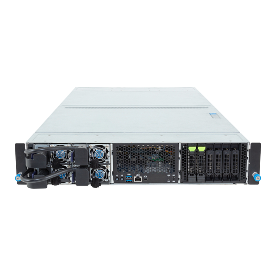
Chapter 2 System Appearance Front View PSU4 PSU2 PSU3 PSU1 2 3 4 Description Front Panel LEDs and Buttons USB 3.2 Gen1 Port x 2 Server Management LAN Port Mini-DP NOTE! Drives with green latches support NVMe. • Please Go to Chapter 2-3 Front Panel LED and Buttons for detail description of function LEDs. System Appearance - 13 -... -
Page 14: Rear View
Rear View PSU2 SLOT 6 SLOT 5 SLOT 4 PSU4 PSU1 SLOT 2 SLOT 1 SLOT 3 PSU3 Description PCIe Card Slot System Appearance - 14 -... -
Page 15: Front Panel Leds And Buttons
Front Panel LEDs and Buttons No. Name Color Status Description Reset Button Press the button to reset the system. Green System is powered on Power button with LED System is not powered on or in ACPI S5 state (power off) Press the button to activate system identification ID Button (Note) -
Page 16: Power Supply Unit (Psu) Led
Power Supply Unit (PSU) LED NOTE! The power supply may be vary based on the system configuration. PSU LED State Description No AC power to all power supplies 1Hz Green Blinking AC present / only standby on / Cold redundant mode 2Hz Green Blinking Power supply firmware updating mode AC cord unplugged or AC power lost;... -
Page 17: Hard Disk Drive Leds
Hard Disk Drive LEDs HDD Present RAID SKU LED #1 Locate Rebuilding HDD Access Fault (No Access) Green ON(*1) BLINK (*2) Disk LED (LED on Back Panel) Amber No RAID configuration Removed HDD Green ON(*1) (via PCH, HBA) Slot (LED on Amber Back Panel) Green... -
Page 18: Chapter 3 System Hardware Installation
Chapter 3 System Hardware Installation Pre-installation Instructions Computer components and electronic circuit boards can be damaged by electrostatic discharge. Working on computers that are still connected to a power supply can be extremely dangerous. Follow the simple guidelines below to avoid damage to your computer or injury to yourself. •... -
Page 19: Removing Chassis Cover
Removing Chassis Cover Before you remove or install the system cover • Make sure the system is not turned on or connected to AC power. Follow these instructions to remove the chassis cover: Remove the screw securing the chassis cover. Push button to unlock the handle. -
Page 20: Installing The Pcie / Gpu Card
Installing the PCIe / GPU Card • Voltages can be present within the server whenever an AC power source is connected. This voltage is present even when the main power switch is in the off position. Ensure that the system is powered-down and all power sources have been disconnected from the server prior to installing a PCI card. - Page 21 Follow these instructions for the PCI Expansion / GPU card: Remove the riser bracket from the system. Loosen and remove the screw securing the slot covers on the riser bracket then detach the slot covers. Unscrew the screws securing the PCIe Card/GPU in the Slot. Alignthe PCIe card/GPU with the riser guide slot, and gently push it in the direction of the arrow until it securely connects to the PCIe card connector.
-
Page 22: Installing The Hard Disk Drive
Installing the Hard Disk Drive Read the following guidelines before you begin to install the HDD: • Take note of the drive tray orientation before sliding it out. • The tray will not fit back into the bay if inserted incorrectly. •... -
Page 23: Installing The M.2 Device And Heat Sink
Installing the M.2 Device and Heat Sink CAUTION The position of the stand-off screw will depend on the size of the M.2 device. Refer to the size of the M.2 device and change the position of the stand-off screw accordingly. WARNING: Please ensure a heatsink is attached to any M.2 device installed into the system. -
Page 24: Replacing The Fan Assembly
Replacing the Fan Assembly • Voltages can be present within the server whenever an AC power source is connected. This voltage is present even when the main power switch is in the off position. Ensure that the system is powered-down and all power sources have been disconnected from the server prior to replacing a system fan. -
Page 25: Replacing The Power Supply
Replacing the Power Supply CAUTION! • In order to reduce the risk of injury from electric shock, disconnect AC power from the power supply before removing the power supply from the system Follow these instructions to replace the power supply: Flip and then grasp the power supply handle. -
Page 26: Cable Routing
Cable Routing Motherboard: FP_JLFP1 Signal Cable Front IO Board: JLFP1 Motherboard: J20 MCIO Cable Front IO Board: FP_IO Motherboard: PWR_IO Power Cable Front IO Board: PWR_FP System Hardware Installation - 26 -... - Page 27 GPU 1 GPU 2 GPU 3 GPU 4 GPU 5 GPU 6 System Hardware Installation - 27 -...
- Page 28 Motherboard: U2_P0_P2A MCIO Cable Backplane Board: U_2_0 Motherboard: U2_P0_P2B MCIO Cable Backplane Board: U_2_1 GPU Tray: Slot3 Power Cable Powe Distribution Board: RIS_PWR_S3 GPU Tray: Slot6 Power Cable Powe Distribution Board: RIS_PWR_S6 GPU Tray: Slot2 Power Cable Powe Distribution Board: RIS_PWR_S2 GPU Tray: Slot1 Power Cable Powe Distribution Board: RIS_PWR_S1...
-
Page 29: Chapter 4 Motherboard Components
Chapter 4 Motherboard Components Motherboard Components Default Enable SPI/ESPI Select Switch Clear CMOS 1 2 3 ESPI Mode SPI Mode CLR_CMOS NVDIA GRACE CPU Superchip Motherboard Components - 29 -... - Page 30 Item Code Description PWR_IO IO Board Power Connector BP_1 HDD Backplane Board Connector FP_JLFP1 Front Panel Header PWR_FP1 Front IO Board Power Connector M2_0 M.2 Slot(PCIe5x4, Support NGFF-2280/22110) M2_1 M.2 Slot(PCIe5x4, Support NGFF-2280/22110) Battery Socket JPWR10 2 x 4 Pin 12V Power Connector JPWR9 2 x 4 Pin 12V Power Connector JPWR4...
-
Page 31: Jumper Setting
Jumper Setting Default Enable SPI/ESPI Select Switch Clear CMOS 1 2 3 ESPI Mode SPI Mode CLR_CMOS NVDIA GRACE CPU Superchip Motherboard Components - 31 -... -
Page 32: Backplane Board Storage Connector
Backplane Board Storage Connector 4-3-1 CBPX060 Item Description MCIO Connector (U_2_0) MCIO Connector (U_2_1) MCIO Connector (U_2_2) MCIO Connector (U_2_3) MCIO Connector (U_2_4) MCIO Connector (U_2_5) Motherboard Components - 32 -... -
Page 33: Chapter 5 Bios Setup
Chapter 5 BIOS Setup BIOS (Basic Input and Output System) records hardware parameters of the system in the EFI on the motherboard. Its major functions include conducting the Power-On Self-Test (POST) during system startup, saving system parameters, loading the operating system etc. The BIOS includes a BIOS Setup program that allows the user to modify basic system configuration settings or to activate certain system features. - Page 34 Main This setup page includes all the items of the standard compatible BIOS. Advanced This setup page includes all the items of AMI BIOS special enhanced features. (ex: Auto detect fan and temperature status, automatically configure hard disk parameters.) ...
-
Page 35: The Main Menu
The Main Menu Once you enter the BIOS Setup program, the Main Menu (as shown below) appears on the screen. Use arrow keys to move among the items and press <Enter> to accept or enter other sub-menu. Main Menu Help The on-screen description of a highlighted setup option is displayed on the bottom line of the Main Menu. - Page 36 Parameter Description BIOS Information Displays the current access level depending on the type of password protection used. (If no password is set, the default will display as Administrator.) The Administrator level Access Level allows you to make changes to all BIOS settings;...
- Page 37 Processor Information CPU Brand String/ Processor Core/ Displays the technical information for the installed processor(s). Processor Speed Memory Information (Note2) Total Memory Displays the total memory size of the installed memory. Memory Frequency Displays the installed memory frequency information. Memory Slot Information Press [Enter] for advanced items.
-
Page 38: Advanced Menu
Advanced Menu The Advanced Menu displays submenu options for configuring the function of various hardware components. Select a submenu item, then press <Enter> to access the related submenu screen. BIOS Setup - 38 -... -
Page 39: Trusted Computing
5-2-1 Trusted Computing Parameter Description Configuration Enable/Disable BIOS support for security device. OS will not show security device. TCG EFI protocol and INT1A interface will not be Security Device Support available. Options available: Disable, Enable. Default setting is Enable. BIOS Setup - 39 -... -
Page 40: Uefi Variables Protection
5-2-2 UEFI Variables Protection Parameter Description Control he NVRAM Runtime Variables protection through System Password protection of Runtime Admin Password. Variables Options available: Disabled, Enabled. Default setting is Enabled. BIOS Setup - 40 -... -
Page 41: Serial Port Console Redirection
5-2-3 Serial Port Console Redirection Parameter Description Console redirection enables the users to manage the system from a COM1 Console remote location. Redirection (Note) Options available: Enabled, Disabled. Default setting is Disabled. Press [Enter] to configure advanced items. Please note that this item is configurable when COM1 Console Redirection is set to Enabled. - Page 42 Parameter Description Parity Š – A parity bit can be sent with the data bits to detect some transmission errors. – Even: parity bit is 0 if the num of 1's in the data bits is even. – Odd: parity bit is 0 if num of 1's in the data bits is odd. –...
- Page 43 Parameter Description Serial Port for Out-of-Band Management / Windows EMS console redirection allows the user to configure Console Redirection Emergency Management Settings to support Out-of-Band Serial Port management. Services (EMS) Console Options available: Enabled, Disabled. Default setting is Disabled. Redirection (Note) Press [Enter] to configure advanced items.
-
Page 44: Pci Subsystem Settings
5-2-4 PCI Subsystem Settings BIOS Setup - 44 -... - Page 45 Parameter Description PCI Bus Driver Version Displays the PCI Bus Driver version information. When enabled, this setting will initialize the device expansion PCI_# IO ROM ROM for the related PCI-E slot. (Note1) Options available: Enabled, Disabled. Default setting is Enabled. PCI Devices Common Settings Value to be programmed into PCI Latency Timer Register.
- Page 46 5-2-4-1 PCI Express Device Register Settings Parameter Description PCI Express Device Register Settings Press [Enter] for configuration of advanced items. Enable/Disable PCI Express Device Relaxed Ordering feature. Relaxed Ordering Options available: Enabled, Disabled. Default setting is Enabled. When this feature is enabled, the system will allow device to use 8-bit Tag field as are requester.
- Page 47 Parameter Description PCI Express Link Register Settings Set the ASPM level Force L0s - Force all links to L0s Sate. ASPM Support Options available: Auto, Disabled, L0s. Default setting is Disabled. When this feature is enabled, the system will allow generation of Extended Synchronization patterns.
- Page 48 5-2-4-2 PCI Express GEN 2 Settings BIOS Setup - 48 -...
- Page 49 Parameter Description PCI Express GEN2 Device Register Settings ARI Forwarding Š – If supported by hardware and set to 'Enabled', the Downstream Port disables its traditional Device Number field being 0 enforcement when turning a Type1 Configuration Request into a Type0 Configuration Request, permitting access to Extended Functions in an ARI Device immediately below the Port.
- Page 50 Parameter Description PCI Express GEN2 Device Register Settings LTR Mechanism Enable Š – If supported by hardware and set to 'Enabled', this enables the Latency Tolerance Reporting (LTR) Mechanism. Options available: Enabled/Disabled. Default setting is Disabled. End-End TLP Prefix Blocking Š...
-
Page 51: Info Report Configuration
5-2-5 Info Report Configuration Parameter Description Info Report Configuration Post report enabled/disabled. Post Report Options available: Enabled, Disabled. Default setting is Enabled. Delay Time Press <+>/<-> to configure the value. Error Message Report Enable/Disable the POST Error Message support. Info Error Message Options available: Enabled, Disabled. -
Page 52: Usb Configuration
5-2-6 USB Configuration Parameter Description USB Configuration USB Module Version Displays the USB module version information. USB Controllers Displays the supported USB controllers. USB Devices: Displays the USB devices connected to the system. Enable/Disable the XHCI Hand-off support. XHCI Hand-off Options available: Enabled, Disabled. -
Page 53: Network Stack Configuration
5-2-7 Network Stack Configuration Parameter Description Enable/Disable the UEFI network stack. Network Stack Options available: Enabled, Disabled. Default setting is Enabled. Enable/Disable the Ipv4 PXE feature. Ipv4 PXE Support Options available: Enabled, Disabled. Default setting is Enabled. Enable/Disable the Ipv4 HTTP feature. Ipv4 HTTP Support Options available: Enabled, Disabled. -
Page 54: Ip Configuration Settings
5-2-8 IP Configuration Settings Parameter Description Allows user to set IP. Auto Configuration Options available: Disabled, Every Boot, On Demand. Default setting is Disabled. BIOS Setup - 54 -... -
Page 55: Nvme Configuration
5-2-9 NVMe Configuration Parameter Description NVMe Configuration Displays the NVMe devices connected to the system. BIOS Setup - 55 -... -
Page 56: Graphic Output Configuration
5-2-10 Graphic Output Configuration Parameter Description Selects output device type. Output Device Type Options available: First loaded Device, Onboard Device, External Device, Specific Device. Default setting is Onboard Device. Selects OS graphic output. OS graphics output Options available: Controlled by OS, Controller and NameSpace Test. Default setting is Controlled by OS. -
Page 57: Power Restore Configuration
5-2-11 Power Restore Configuration Description Parameter Specify what state when power is re-applied after a power failure (G3 state). Power Restore Options available: Last State/Power On/Power Off. Default setting is Power off. BIOS Setup - 57 -... -
Page 58: Tls Auth Configuration
5-2-12 Tls Auth Configuration Parameter Description Press [Enter] for configuration of advanced items. Enroll Cert Š – Press [Enter] to enroll a certificate • Enroll Cert Using File • Cert GUID Server CA Configuration Input digit character in 1111111-2222-3333-4444-1234567890ab format. –... -
Page 59: Ram Disk Configuration
5-2-13 RAM Disk Configuration Parameter Description Specifies the type of memory to use from available memory pool in system to create a disk. Disk Memory Type Options available: Boot Service Data, Reserved. Default setting is Boot Service Data. Creates a raw RAM disk. Size (Hex) Š... -
Page 60: Intel(R) I350 Gigabit Network Connection
5-2-14 Intel(R) i350 Gigabit Network Connection BIOS Setup - 60 -... - Page 61 Description Parameter Press [Enter] to configure advanced items. Link Speed Š – Allows for automatic link speed adjustment. – Options available: Auto Negotiated, 10 Mbps Half, 10 Mbps Full, 100 Mbps Half, 100 Mbps Full. Default setting is Auto Negotiated. Wake On LAN NIC Configuration Š...
-
Page 62: Mac Ipv4 Network Configuration
5-2-15 MAC IPv4 Network Configuration Parameter Description Indicates whether network address is configured successfully or not. Configured Options available: Enabled, Disabled. Default setting is Disabled. Options available: Enabled, Disabled. Default setting is Disabled. Enable DHCP (Note) Local IP Address Press [Enter] to configure local IP address. (Note) Press [Enter] to configure local NetMask. -
Page 63: Mac Ipv6 Network Configuration
5-2-16 MAC IPv6 Network Configuration Parameter Description Press [Enter] to configure advanced items. Displays the MAC Address information. Š Interface ID Š – The 64 bit alternative interface ID for the device. The string is colon separated. e.g. ff:dd:88:66:cc:1:2:3. DAD Transmit Count Š... -
Page 64: Driver Health
5-2-17 Driver Health Parameter Description Driver Health Displays driver health status of the devices/controllers if installed BIOS Setup - 64 -... -
Page 65: Chipset Menu
Chipset Menu The Chipset Setup menu displays submenu options for configuring the chipset functions. Select a submenu item, then press <Enter> to access the related submenu screen. BIOS Setup - 65 -... - Page 66 5-3-1 NVIDIA Configuration BIOS Setup - 66 -...
-
Page 67: Nvidia Configuration
Description Parameter Press [Enter] to configure advanced items. Serial Port Configuration Š – Used to select serial port configuration. NVIDIA Configuration • Option available: Console Enabled -SBSA, Port Disabled, Serial Deebug Enabled -SBSA. Default setting is Console Enabled -SBSA. Press [Enter] to configure advanced items. Enable ACPI Timer Š... -
Page 68: Server Management Menu
Server Management Menu Parameter Description Enable/Disable interfaces to communicate with BMC. BMC Support Options available: Enabled, Disabled. Default setting is Enabled. Enable/Disable FRB-2 timer (POST timer). FRB-2 Timer Options available: Enabled, Disabled. Default setting is Enabled. FRB-2 Timer (Note1) Configures the FRB2 Timer timeout. The value is between 1 to 30 minutes. timeout Default setting is 6 minutes. - Page 69 Parameter Description System Event Log Press [Enter] to configure advanced items. View FRU Press [Enter] to view the FRU information. Information BMC self test log Press [Enter] to configure advanced items. BMC VLAN Press [Enter] to configure advanced items. Configuration BMC network Press [Enter] to configure advanced items.
-
Page 70: System Event Log
5-4-1 System Event Log Parameter Description Enabling / Disabling Options Change this item to enable or disable all features of System Event SEL Components Logging during boot. Options available: Enabled, Disabled. Default setting is Enabled. Erasing Settings Choose options for erasing SEL. Options available: No, Erase SEL Yes, On next reset,... -
Page 71: View Fru Information
5-4-2 View FRU Information The FRU page is a simple display page for basic system ID information, as well as System product information. Items on this window are non-configurable. (Note) The model name will vary depends on the product you purchased BIOS Setup - 71 -... -
Page 72: Bmc Self Test Log
5-4-3 BMC self test log Description Parameter Options available: No/Yes, On next reset/Yes, On every reset. Erase Log Default setting is No. Configuration for reactions to a full log. Option available: Do not log any more/Clear Log. When Log is full Default setting is Do not log any more. -
Page 73: Bmc Vlan Configuration
5-4-4 BMC VLAN Configuration Description Parameter BMC VLAN Configuration Select to configure BMC VLAN ID. The valid range is from 0 to 4094. When BMC VLAN ID set to 0, BMC VLAN ID will be disabled. Select to configure BMC VLAN Priority. The valid range is from 0 to 7. BMC VLAN Priority When BMC VLAN ID is set to 0, BMC VLAN Priority will not be selected. -
Page 74: Bmc Network Configuration
5-4-5 BMC Network Configuration Parameter Description BMC network configuration Select NCSI and Dedicated Options available: Do Nothing, Model1(Dedicated), Model2(NCSI), Mode3(Failover). Default setting is Do Nothing. Lan Channel 1 Selects to configure LAN channel parameters statically or dynamically (DHCP). Configuration Address source Options available: Unspecified, Static, DynamicBmcDhcp. -
Page 75: Ipv6 Bmc Network Configuration
5-4-6 IPv6 BMC Network Configuration Parameter Description IPv6 BMC network configuration IPv6 BMC Lan Channel 1 Enable/Disable IPv6 BMC LAN channel function. When this item is disabled, the system will not modify any BMC network during BIOS IPv6 BMC Lan Option phase. -
Page 76: Security Menu
Security Menu The Security menu allows you to safeguard and protect the system from unauthorized use by setting up access passwords. There are two types of passwords that you can set: • Administrator Password Entering this password will allow the user to access and change all settings in the Setup Utility. •... -
Page 77: Boot Menu
Boot Menu The Boot menu allows you to set the drive priority during system boot-up. BIOS setup will display an error message if the legacy drive(s) specified is not bootable. Parameter Description Boot Configuration Number of seconds to wait for setup activation key. 65535 (0xFFFF) Setup Prompt Timeout means indefinite waiting. - Page 78 Parameter Description FIXED BOOT ORDER Priorities Press [Enter] to configure the boot order priority. By default, the server searches for boot devices in the following sequence: Hard drive. Boot Option #1 / #2 / #3 / #4 / #5 CD-COM/DVD drive. USB device.
-
Page 79: Save & Exit Menu
Save & Exit Menu The Save & Exit menu displays the various options to quit from the BIOS setup. Highlight any of the exit options then press <Enter>. Parameter Description Save Options Saves changes made and closes the BIOS setup. Save Changes and Exit Options available: Yes, No. - Page 80 Parameter Description Default Options Loads the default settings for all BIOS setup parameters. Setup Defaults are quite demanding in terms of resources consumption. If you are using low-speed memory chips or other kinds of low-performance components Restore Defaults and you choose to load these settings, the system might not function properly.
-
Page 81: Bios Recovery
BIOS Recovery The system has an embedded recovery technique. In the event that the BIOS becomes corrupt the boot block can be used to restore the BIOS to a working state. To restore your BIOS, please follow the instructions listed below: Recovery Instruction: 1.
Need help?
Do you have a question about the XV23-VC0-AAJ1 and is the answer not in the manual?
Questions and answers