Table of Contents
Advertisement
Quick Links
Advertisement
Table of Contents

Related Manuals for Energie AQUAPURA 8HT


Summary of Contents for Energie AQUAPURA 8HT
- Page 1 USER AND INSTALLATION MANUAL USER AND INSTALLATION MANUAL Aquapura HT AQUAPURA 8HT AQUAPURA 12HT AQUAPURA 14HT / 14HT T AQUAPURA 22HT T Directives: Revision:00 2014/35/UE Version 00 2014/30/UE Date: 14/11/2024 Regulation nº 814/2013 Regulation nº 812/2013...
- Page 2 USER AND INSTALLATION MANUAL Esteemed Client, We would like to thank you for your choice when you acquired an equipment for sanitary water heating. AQUAPURA INVERTER HT aero-thermal system will surely meet all your expectations and provide many years of comfort with maximum power saving. Our organization dedicates much time, energy and economic resources in order to develop innovations that will promote power saving in our products.
-
Page 3: Table Of Contents
Installer responsibility ....................9 TRANSPORT ........................... 9 PRINCIPLE OF OPERATION ....................10 UNIT OVERVIEW ........................10 UNIT DIMENSIONS ......................11 Aquapura 8HT ......................11 Aquapura 12 HT ......................12 Aquapura 14HT ......................13 Aquapura 22 HT T ...................... 14 TECHNICAL INFO ........................15 PERFORMANCE ........................ - Page 4 USER AND INSTALLATION MANUAL 11.6 Connections terminals – Outputs ................28 ROOM THERMOSTAT INSTALLATION ................29 MAIN CONTROLLER --- USER INTERFACE ............... 30 13.1 User interface description ..................30 13.2 Unlock screen ......................31 13.3 Operation mode switch ..................... 31 13.4 Setting target temperature ..................
- Page 5 USER AND INSTALLATION MANUAL 17.4 Central Heating and Cooling with buffer tank + DHW ..........56 17.5 Central Heating and Cooling + DHW ................57 17.6 Domestic hot water ....................58 WARRANTY ........................59...
-
Page 6: Information
USER AND INSTALLATION MANUAL 1 INFORMATION This manual is intended as an aid to qualified service personnel for proper installation, operation and maintenance of the Heat Pump. Read this manual carefully before attempting to install or operate the Heat Pump. Failure to follow these instructions may cause a fault of the Heat Pump, resulting in electrical shock, scald injury and/or property damage. -
Page 7: Danger Info
USER AND INSTALLATION MANUAL 2.1 Danger Info INSTALLATION: Description The heat pump must be installed by qualified personals, to avoid improper installation which can lead to water leakage, electrical shock or fire. Please make sure that the unit and power connection have good earthing, DANGER otherwise may cause electrical shock. -
Page 8: Warning Info
USER AND INSTALLATION MANUAL Warning Info INSTALLATION: Description The unit CANNOT be installed near the flammable gas. Once there is any leakage of the gas, fire can occur. Make sure that the basement of the heat pump is strong enough, to avoid any decline or fall down of the unit. -
Page 9: Installer Responsibility
USER AND INSTALLATION MANUAL Installer responsibility The installer is responsible for proper installation of the equipment and start with its operation. The installer should note the following notes: Carefully read and follow the instructions of the manuals supplied with the equipment; •... -
Page 10: Principle Of Operation
USER AND INSTALLATION MANUAL Description The unit has been tested and inspected prior to shipment from the manufacturer for quality assurance. Carefully inspect the equipment components upon receipt to ensure that the equipment has not been damaged in transit. WARNNING Confirm that all ordered parts have been received as specified and that unit type, size, and voltage are correct. -
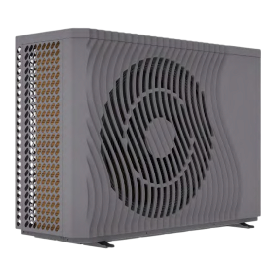
Page 11: Unit Dimensions
USER AND INSTALLATION MANUAL 7 UNIT DIMENSIONS 7.1 Aquapura 8HT Dimension 1167 (mm) (Outlet Water) (Inlet Water) Dimension 1” 1” (Inches) -
Page 12: Aquapura 12 Ht
USER AND INSTALLATION MANUAL 7.2 Aquapura 12 HT Dimension 1167 (mm) (Outlet Water) (Inlet Water) Dimension 1” 1” (Inches) -
Page 13: Aquapura 14Ht
USER AND INSTALLATION MANUAL 7.3 Aquapura 14HT Dimension 1287 (mm) (Outlet Water) (Inlet Water) Dimension 1” 1” (Inches) -
Page 14: Aquapura 22 Ht T
USER AND INSTALLATION MANUAL 7.4 Aquapura 22 HT T Dimension 1247 1329 (mm) (Outlet Water) (Inlet Water) Dimension 1” 1” (Inches) -
Page 15: Technical Info
USER AND INSTALLATION MANUAL TECHNICAL INFO Aquapura 8HT Power supply 240V~/50Hz Refrigerant / Charge / Kg R290 / 0,500 / 0,0015 Heating Heating capacity range (min/ max) 4,67 ~ 10,3 Electrical power range 0,71 ~ 2,9 Rated thermal power supplied ¹... - Page 16 USER AND INSTALLATION MANUAL Aquapura 12HT Power supply 240V~/50Hz Refrigerant / Charge / Kg 0,8 / 0,002 Heating Heating capacity range (min/ max) 6,2-14,5 Electrical power range 2,2-3,16 Rated thermal power supplied ¹ 12,3 Rated electrical power consumption¹ COP¹ 4,92 Cooling Cooling capacity range (min / max) 4,8-11,6...
- Page 17 USER AND INSTALLATION MANUAL Aquapura 14HT Aquapura 14HT-T Power supply 240V~/50Hz 400V~/3P+N/50Hz Refrigerant / Charge/CO2 Eq. / Kg/ton R290 / 0,850/0,0025 Heating Heating capacity range (min/ max) 6,18~ 16,70 6,18~ 16,70 Electrical power range 1,45 ~ 4,67 1,45 ~ 4,67 Rated thermal power supplied ¹...
- Page 18 USER AND INSTALLATION MANUAL Aquapura 22HT T Power supply 380-415V/3N ̴ / 50Hz Refrigerant / Charge / Kg R290 / 1,30 Heating Heating capacity range (min/ max) 9,67 ~ 25,47 Electrical power range 1,60 ~ 8,31 Rated thermal power supplied ¹ 22,00 Rated electrical power consumption¹...
-
Page 19: Performance
USER AND INSTALLATION MANUAL 9 PERFORMANCE Aquapura 8HT 9.2 Aquapura 12 HT AQUAPURA INVERTER 12HT Temperatura ambiente (ºC) Outlet temperature 35ºC Outlet temperature 45ºC Outlet temperature 55ºC... -
Page 20: Aquapura 14Ht/ Aquapura 14 Ht T
USER AND INSTALLATION MANUAL 9.3 Aquapura 14HT/ Aquapura 14 HT T 9.4 Aquapura 22 HT T... -
Page 21: Installation
USER AND INSTALLATION MANUAL 10 INSTALLATION 10.1 Installation place Before starting any installation procedure, check that the base of the place where the equipment will be placed is perfectly level. This prevents the compressor lubricating oil from working outside the indicated levels. Look for a place with an even, safe and resistant floor, preferably in concrete, taking into account the weight of the machine. -
Page 22: Hydraulic Installation
USER AND INSTALLATION MANUAL 10.3 Hydraulic installation Take the following points into account when executing the hydraulic circuit: Reduce as much as possible the number of bends in the pipes to reduce pressure • drops in the installation; Ensure system fittings, dowels, water pumps and valves are designed for full flow •... -
Page 23: Circuit Water Quality
USER AND INSTALLATION MANUAL 10.5 Circuit water quality The composition and quality of the water in the system has a direct effect on the performance of the entire system and the lifetime of the heat pump. For the initial charging and backfill of the system, usually normal tap water with a pH value of 7-8 can be used as long as the water is not highly corrosive (chloride content >... -
Page 24: Temperature Probes Info
USER AND INSTALLATION MANUAL 10.7 Temperature probes info 11 ELECTRICAL REQUIREMENTS 11.1 Main specifications Description • The installation of the electrical network must be carried out in accordance with local regulations in force and by a qualified professional. • The installer must not make any kind of electrical changes to WARNNING the equipment. -
Page 25: Electrical Main Spcifications/ Protection Devices
WARNNING anomaly in the electrical supply. 11.2 Electrical main spcifications/ protection devices Model Power source Max. current * cable section Aquapura 8HT 240V/50Hz 2,5mm Aquapura 12HT 240V~ /50Hz 4 mm² Aquapura HT 14 240V~ /50Hz 25 A 4 mm²... -
Page 26: Connection Between External Unit And Display (User Interface)
USER AND INSTALLATION MANUAL 11.3 Connection between external unit and display (user interface) The equipment is supplied with a 12 meter cable to interconnect the outdoor unit with the display. If the supplied cable is not long enough and the distance between the outdoor unit and the display is less than 50 meters, we recommend installing a straight-through cable. -
Page 27: Digital Input Configuration
USER AND INSTALLATION MANUAL Description Switching remotely ON or OFF. Terminal • Contact open --- System OFF REMOTE ON/OFF • Contact closed --- System ON Switching remotely to heating or cooling mode; Terminal • Contact open --- Cooling mode; REMOTE HEAT/COOL •... -
Page 28: Connections Terminals - Outputs
USER AND INSTALLATION MANUAL Access the “Parameter” menu; In the “system” menu, change the following parameter: Paramater configuration H07 – Control Mode Display Change to: H07 – Control Mode Dry contact 11.6 Connections terminals – Outputs *Note: The position of these terminals may vary with different models. Please check your electric scheme Descrição Terminal... -
Page 29: Room Thermostat Installation
USER AND INSTALLATION MANUAL V3 - Neutral Terminal Connection terminal for DHW circulating pump. Voltage polarized P1 – Neutral output (230V~) when the DHW function is active. P2 - Phase 12 ROOM THERMOSTAT INSTALLATION The simplest way to improve and control the comfort level of your installation is through an ambient thermostat. -
Page 30: Main Controller
USER AND INSTALLATION MANUAL 13 MAIN CONTROLLER --- USER INTERFACE 13.1 User interface description Number Function Lock screen. Click this key to lock the screen. White represents not enabled, while blue represents enabled Is home icon. This Icon is shown by sliding the main interface. Is tank water temperature. -
Page 31: Unlock Screen
USER AND INSTALLATION MANUAL System time Operation mode Mode key: Domestic Hot water mode; • Heating mode; • Cooling mode; • Domestic hot water + heating mode; • Domestic hot water + cooling mode. • Can be selected by pressing this key. 13.2 Unlock screen Click the lock screen key again while the screen has been locked, pop-up keyboard is shown as following:... -
Page 32: Setting Target Temperature
USER AND INSTALLATION MANUAL There are five modes can be selected after sliding the mode icon. Operation mode Description “Hot water” Domestic hot water mode “Heating” Heating mode “Cooling” Cooling mode “Hot water + Heating” Domestic hot water + Heating mode “Hot water + Cooling”... -
Page 33: Setting Interface Display And Function
USER AND INSTALLATION MANUAL 13.5 Setting interface display and function Swipe from right to left on the main interface to enter the function setting interface, and swipe from left to right on the function setting interface to return to the main interface. The function setting interface is shown in the figure below. -
Page 34: Time Setting
USER AND INSTALLATION MANUAL 13.6 Time setting Num. Description System time setting Mute timer Click to set warm water pump timed cycle, hide the icon when H40=0/2, show the icon when H40=1 Click to set timed mute, hide the icon when H22=0, show the icon when H22=1 13.6.1 System time setting When entering the page of system time setting, the system time will be initialized to the time at the moment when the system time setting button is pressed, and you can adjust the time by... -
Page 35: Mute Timer Setting
USER AND INSTALLATION MANUAL 13.6.2 Mute timer setting Num. Descrição Whether enable the mute timer ON/ OFF function key color: Enable - Blue ON / Disable: Gray OFF The mute timer ON/ OFF setting point. Select from 00:00 to 23:59 The status of mute timer: key color: Enable - Blue ON / Disable: Gray OFF 13.6.3 Power timer setting... -
Page 36: Warm Water Circulation Control Setting
USER AND INSTALLATION MANUAL 13.6.4 Warm water circulation control setting Note: To activate this function you need to set the parameter H40=1 Num. Description Slider to activate the current time setting(ON – Blue icon/OFF – Grey icon) Set week day for the timer Set the time of day, hour a minute, that you want this timer to activate Use the arrows to check the timers on all the pages. -
Page 37: Smart Grid
USER AND INSTALLATION MANUAL Temperature data is collected and saved every five minutes. Timekeeping is made from the latest data saving, if the power is disrupted when the time is less than five minutes, the data during such period will not be saved; Only curve for power-on status is recorded, and that for power-off will not be saved;... -
Page 38: Parameter Z01=1
USER AND INSTALLATION MANUAL 13.8.1 Parameter Z01=1 When only one dry contact is used, the display will show: Select the button “Brief description” to check the various available modes of this function. Select the button “parameter” with the installer password and access the control of the various modes of the SG ready function. -
Page 39: Parameter Z01=2
USER AND INSTALLATION MANUAL 13.8.2 Parameter Z01=2 It is possible to use two dry contacts allowing thus to define 4 different modes of the SG ready function instead of 2. Its possible to define then the functioning of the heat pump according to the energy produced by the solar panels (High, Medium, Low). -
Page 40: Color Display Calibration
USER AND INSTALLATION MANUAL Name Description Activate/deactivate Enable the timer, when the font colour is blue, the timer is active Function description Select to read about this function Time setting Set the timer time Mode Set the target mode. If you do not need to set a mode please write “/”... -
Page 41: Electric Heating
USER AND INSTALLATION MANUAL 13.10 Electric Heating In heating operating mode, tap the “Electric Heating” icon to activate/deactivate the backup resistor (blue resistor icon active/ gray resistor icon deactivates) Note: Resistance is not an integral part of the equipment. Its installation will have to be done separately. -
Page 42: Fault List
USER AND INSTALLATION MANUAL 13.12 Fault list Click the alarm icon on the main interface to access the following interface: Num. Description Fault code Fault description and date/ time Clear all fault records; Number of pages with fault records. -
Page 43: Main Controller -Installer Interface
USER AND INSTALLATION MANUAL 14 MAIN CONTROLLER –INSTALLER INTERFACE To access the user interface, click on the “Parameter” icon and enter the password 022. After entering the password, you will have access to the following menu: “ICON” Description Client Parameters Installer parameters Defrosting Force defrost cycle... -
Page 44: Installer Parameters
USER AND INSTALLATION MANUAL 14.1 Installer parameters Description State / configuration H05 – Enable Cooling Function H07 – Control Mode Display H10 – Unit Address H18 – Electric heater Stage 3 ON for DHW H20 – 3-way valve polarity ON – output (230Vac) OFF –... - Page 45 USER AND INSTALLATION MANUAL R03 – Cooling Target Temp. 7°C R04 – Temp. Diff. for Power-on in Heating 5°C R05 – Temp. Diff. for Standby in Heating 1°C R06 – Temp. Diff. for Power in Cooling 5°C R07 – Temp. Diff. for Standby in Cooling 1°C R16 –...
-
Page 46: Compensation Curve - Outdoor Temperature Vs Setpoint
USER AND INSTALLATION MANUAL 14.2 Compensation curve - Outdoor temperature Vs setpoint When activating the compensation function for outdoor temperature Vs flow water temperature for the central heating circuit, take into account that the setpoint will be adjusted as a function of the temperature defined in the graph. Vertical axis - Impulse water temperature Horizontal axis - Outdoor temperature 14.3 Output/ input state of digital / analogic contacts... -
Page 47: Manual Testing
USER AND INSTALLATION MANUAL 14.5 Manual testing The unit allows the activation of each of its components at a time to check if they are working properly helping with the installation of the machine. This function can be used only when the machine is turned off. -
Page 48: Alarm
USER AND INSTALLATION MANUAL 15 ALARM 15.1 Alarm – Electronic control fault table Fault Protect/fault Reason Elimination methods display The temp. Sensor is broken Inlet Temp Sensor Fault Check or change the temp. Sensor or short circuit Heating returning water The temp. - Page 49 USER AND INSTALLATION MANUAL temperature protection working correctly or the temperature sensor ambient temperature is below A30 Check to see whether the electric heater The electric-heater Aux Superheat Protection E04 has been running under the temperature protection switch is broken over 150 for a long time Water flow is not enough Excess difference between...
-
Page 50: Alarm - Frequency Conversion Board Fault Table
USER AND INSTALLATION MANUAL motor is in bad contact Compressor Overcurrent Check whether the system of the E051 The compressor is overload Shutdown Fault compressor running normally No water/little water in Check the pipe water flow and water Outlet Water Over temp. E065 water system pump No water/little water in... - Page 51 USER AND INSTALLATION MANUAL (Inverter Board) and main board communication failure Check and adjust the current IPM Overheat Stop The IPM module is overheat measurement Input voltage Lacking Check and measure the voltage The input voltage lost phase Phase adjustment Compressor magnetic force Check and adjust the current Weak Magnetic Warn...
-
Page 52: Troubleshooting
USER AND INSTALLATION MANUAL 16 TROUBLESHOOTING Failure Possible causes for the failure Solutions Power supply failure: 1) Check the power supply. 2) Circuit breaker off; 2) Check if there is an anomaly and 3) Power cable not properly turn the circuit breaker back on. BC does not work, display connected;... - Page 53 USER AND INSTALLATION MANUAL 1) Check system leakage and recharge The compressor runs but 1) No gas in the heat pump; 2) Refrigerant; find out the cause and heat pump has not heating 2) Heat exchanger broken; replace the heat exchanger; or cooling capacity 3) Compressor failure.
-
Page 54: Appendix 1 - Hydraulic Schemes
USER AND INSTALLATION MANUAL 17 APPENDIX 1 – HYDRAULIC SCHEMES Description • This drawing just shows the core parts and main principle of the application, there are many parts can be installed such as water pressure meters, water temperature meter, drainage etc. •... -
Page 55: Central Heating And Cooling
USER AND INSTALLATION MANUAL 17.2 Central Heating and Cooling We recommend installing an inertia tank of between 50 and 80 liters in the return line. 17.3 Central Heating and Cooling with buffer tank... -
Page 56: Central Heating And Cooling With Buffer Tank + Dhw
USER AND INSTALLATION MANUAL Description The heat pump does not control the pump “P1”, its control must be carried out separately. ATTENTION 17.4 Central Heating and Cooling with buffer tank + DHW Description The heat pump does not control the pump “P1”, its control must be carried out separately The heat pump manages the three-way valve depending on the requested request (Central heating or DHW). -
Page 57: Central Heating And Cooling + Dhw
USER AND INSTALLATION MANUAL 17.5 Central Heating and Cooling + DHW We recommend installing an inertia tank of between 50 and 80 liters in the return line. Description The heat pump manages the three-way valve depending on the requested request (Central heating or DHW). The DHW temperature probe (TT) is provided with system. -
Page 58: Domestic Hot Water
USER AND INSTALLATION MANUAL 17.6 Domestic hot water Description The DHW temperature probe (TT) is provided with system. The temperature probe is located inside the installation kit ATTENTION... -
Page 59: Warranty
USER AND INSTALLATION MANUAL 18 WARRANTY This warranty covers all defects to the confirmed materials, excluding the payment of any type of personal damage indemnity caused directly or indirectly by the materials. The periods indicated below start from the purchase date of the apparatus, 6 months at the latest from the leaving date from our storage warehouses. - Page 60 USER AND INSTALLATION MANUAL period; The warranty lapses if this certificate is incorrectly filled in, if it is violated or if it is • returned after more than 15 days have passed since the purchase date of the apparatus. Water cylinder that are working in waters with the following indices: •...
Need help?
Do you have a question about the AQUAPURA 8HT and is the answer not in the manual?
Questions and answers