Advertisement
Quick Links
Installation, Operation,
and Maintenance
Packaged Rooftop Air Conditioners
Foundation™ Gas/Electric
15 to 25 Tons, 60Hz
Model Numbers:
Only qualified personnel should install and service the equipment. The installation, starting up, and servicing of heating, ventilating, and air-
conditioning equipment can be hazardous and requires specific knowledge and training. Improperly installed, adjusted or altered equipment
by an unqualified person could result in death or serious injury. When working on the equipment, observe all precautions in the literature and
on the tags, stickers, and labels that are attached to the equipment.
April 2018
GBC180-300
SAFETY WARNING
RT-SVX51D-EN
Advertisement

Related Manuals for Ingersoll-Rand GBC180-300


Summary of Contents for Ingersoll-Rand GBC180-300
- Page 1 Foundation™ Gas/Electric 15 to 25 Tons, 60Hz Model Numbers: GBC180-300 SAFETY WARNING Only qualified personnel should install and service the equipment. The installation, starting up, and servicing of heating, ventilating, and air- conditioning equipment can be hazardous and requires specific knowledge and training. Improperly installed, adjusted or altered equipment by an unqualified person could result in death or serious injury.
- Page 2 Introduction Read this manual thoroughly before operating or servicing this unit. WARNING Warnings, Cautions, and Notices Proper Field Wiring and Grounding Required! Safety advisories appear throughout this manual as Failure to follow code could result in death or serious required. Your personal safety and the proper operation of injury.
- Page 3 Introduction Copyright WARNING This document and the information in it are the property of Follow EHS Policies! Trane, and may not be used or reproduced in whole or in Failure to follow instructions below could result in part without written permission. Trane reserves the right death or serious injury.
- Page 4 Table of Contents Model Number Description (LLE) Troubleshooting ....39 ....5 Resetting Cooling and Heating Lockouts .
- Page 5 Model Number Description Model Number Description Low Leak Economizer, Digit 1 — Unit Type Comparative Enthalpy w/o Packaged Gas/Electric Barometric Relief Digit 2 — Efficiency Digit 15 — Supply Fan/Drive ASHRAE 90.1 - 2013 Type/Motor Digit 3 — Airflow Configuration Standard Motor Convertible Oversized Motor...
- Page 6 General Information Unit Inspection additional respiratory protection. Use the appropriate NIOSH approved respiration in these situations. As soon as the unit arrives at the job site: First Aid Measures • Verify that the nameplate data matches the data on the •...
- Page 7 General Information JADE Economizer Control - Low Leak Power Exhaust Control (Optional) Economizer (LLE) Only The power exhaust fan is started whenever the position of the economizer dampers meets or exceed the power The JADE controller is a standalone economizer controller exhaust setpoint when the indoor fan is on.
- Page 8 General Information programmable, wall-mounted thermostat, and it can be initiating a call to cool when the damper is at 100% open. used for economizer operation. The Economizer mode is controlled by the MAT getting above the MAT SET setting while the OAT is below the Sensor DRYBLB SET setting.
- Page 9 Dimensional Data Figure 1, p. 12 illustrates the minimum operating and service clearances for either a single or multiple unit installation. These clearances are the minimum distances necessary to assure adequate serviceability, cataloged unit capacity, and peak operating efficiency. Providing less than the recommended clearances may result in condenser coil starvation, “short-circuiting”...
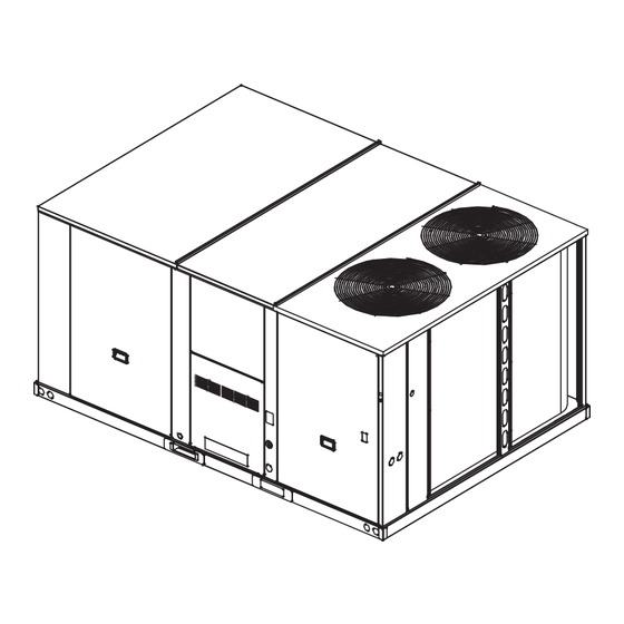
- Page 10 Dimensional Data Figure 2. Gas/electric units — overview (G*C UNITS ONLY) (G*C UNITS - TBU GAS ONLY) Figure 3. Gas/electric units — front & side views — 15–25 tons standard efficiency RT-SVX51D-EN...
- Page 11 Dimensional Data Figure 4. Gas/electric units — plan view — 15–25 tons standard efficiency 82 1/4" Figure 5. Foundation units — back view (horizontal configuration) — 15–25 tons standard efficiency RT-SVX51D-EN...
- Page 12 Dimensional Data Figure 6. Roof curb —15–25 tons standard efficiency Figure 7. Downflow duct connections—field fabricated 15–25 tons standard efficiency Notes: • Duct flanges mount 7-7/16” down inside the curb on the 1-1½” curb flanges. • Roofcurb is intended for downflow use only. 1”...
- Page 13 Dimensional Data Figure 8. Downflow unit clearance — 15–25 tons standard efficiency Figure 9. Barometric relief and economizer— 15–25 tons standard efficiency MOTORIZED DAMPER FOR LOW LEAK) FOR LOW LEAK) BAROMETRIC RELIEF IS FOR USE WITH A DOWNFLOW ECONOMIZER ONLY RT-SVX51D-EN...
- Page 14 Dimensional Data Figure 10. Manual damper — 15–25 tons standard efficiency RT-SVX51D-EN...
- Page 15 Unit Weights Table 1. Maximum unit & corner weights (lb) and center of gravity dimensions (in.) (a), (b) Weights (lb) Corner Weights Center of Gravity (in.) Unit Tons Model No. Shipping Length Width GBC180 2310 1990 17½ GBC210 2319 1999 GBC240 2344 2024...
- Page 16 Installation Unit Foundation When attaching the ductwork to the unit, provide a water- tight flexible connector at the unit to prevent operating sounds from transmitting through the ductwork. WARNING All outdoor ductwork between the unit and the structure should be weather proofed after installation is completed. Risk of Roof Collapsing! Note: For sound consideration, cut only the holes in the Confirm with a structural engineer that the roof...
- Page 17 Installation External Vent Hood Installation • Ensure unit-to-curb seal is tight and without buckles or cracks. Note: This procedure applies only to medium and high • Install and connect a condensate drain line to the heat options, not to the low heat option. evaporator drain connection.
- Page 18 Installation 3. Install the vent hood on the gas heat panel using the Figure 17. Factory installed down flow TCO1 limit screws removed in Step 1. Make sure it is properly location secured on to the panel. Figure 15. Vent hood installation 4.
- Page 19 Installation Optional TBUE Wiring (Through the Base NOTICE: Electrical Option) Use Copper Conductors Only! • Location of the applicable electrical service is Unit terminals are not designed to accept other types of illustrated below. Refer to the customer connection conductors. Failure to use copper conductors could diagram that is shipped with the unit for specific result in equipment damage.
- Page 20 Installation Requirements for Gas Heat 1. Use copper conductors unless otherwise specified. 2. Ensure that the AC control wiring between the controls The unit gas train and optional through-the-base gas shut- and the unit’s termination point does not exceed three off valve are rated at 1/2 PSIG maximum.
- Page 21 Installation Voltage Imbalance Table 4. Piping Three phase electrical power to the unit must meet Iron Pipe Size (IPS) Inches stringent requirements for the unit to operate properly. Length of Pipe (ft) ½” Pipe ¾” Pipe 1” Pipe 1¼” Pipe 1½” Pipe Measure each leg (phase-to-phase) of the power supply.
- Page 22 Installation temperature during the “Off” cycle to reduce oil foaming during compressor starts. Oil foaming occurs when WARNING refrigerant condenses in the compressor and mixes with Hazardous Voltage! the oil. In lower ambient conditions, refrigerant migration to the compressor could increase. Disconnect all electric power, including remote disconnects before servicing.
- Page 23 Factory-Mounted Unit Options Unit Disconnect (FIYUDC) Note: Wire size for the length of run should be determined using the circuit ampacity found on the unit nameplate and the N.E.C. WARNING 4. Route low voltage (class II), control wiring through hole in base of unit but not through high voltage Hazardous Voltage w/Capacitors! conduit.
- Page 24 Factory-Mounted Unit Options Through the Base Gas Utility Important: All phases of this installation must comply with NATIONAL, STATE, and LOCAL Option CODES. In absence of local codes, the installation must conform with American This section contains the instructions for making field National Standard-Z223.1a- National Fuel connections to the Through the Base Gas Utility Option.
- Page 25 Pre Start Verifying Proper Air Flow (Units with Belt Drive Indoor Fan) Much of the systems performance and reliability is closely associated with, and dependent upon having the proper airflow supplied both to the space that is being conditioned and across the evaporator coil. The indoor fan speed is changed by opening or closing the adjustable motor sheave.
- Page 26 Start Up Sequence Of Operation indoor fan relay (F) coil is de-energized with heater contactors. These units are offered with electromechanical controls. When the thermostat fan selection switch is set to the "On" position, the thermostat keeps the indoor fan relay coil (F) Note: The Condensate Overflow Switch (COF) (optional) energized for continuous fan motor operation.
- Page 27 Start Up "On" and "Off" as required to maintain the zone Table 8. Ignition module diagnostics temperature setpoint. Flame sensed and gas valve not energized or Five blinks flame sensed and no call for heat. Electromechanical Control Heating Operation Flame rollout (CBM failure, incorrect gas (for Gas Units) pressure, and incorrect primary air).
- Page 28 Start Up Low Pressure Cutout When there is a call for Cool 2, the second compressor is energized and the Supply Fan will switch to High Speed. The low pressure cutouts are wired in series with the high The unit will stage down compressors for cooling in pressure cutouts and the temperature discharge limits.
- Page 29 Start Up Jade Controls - Low Leak Economizer Sequence of Operation Table 9. Dry bulb operation no DCV (CO sensor) - 1 speed fan OA Good to economize? Y1-I Y2-I FAN SPD Y1-O Y2-O Occupied Unoccupied High 0-v/Off 0-v/Off MIN POS Closed None High...
- Page 30 Start Up Table 11. Enthalpy operation no DCV (CO sensor) - 1 speed fan OA Good to economize? Y1-I Y2-I FAN SPD Y1-O Y2-O Occupied Unoccupied High 0-v/Off 0-v/Off MIN POS Closed High 24-v/On 0-v/Off MIN POS Closed None High 24-v/On 24-v/On MIN POS...
- Page 31 Start Up Table 13. Dry bulb operation no DCV (CO sensor) - 2 speed fan OA Good to economize? Y1-I Y2-I FAN SPD Y1-O Y2-O Occupied Unoccupied 0-v/Off 0-v/Off MIN POS L Closed None 24-v/On 0-v/Off MIN POS L Closed High 24-v/On 24-v/On...
- Page 32 Start Up Table 15. Enthalpy operation no DCV (CO sensor) - 2 speed fan OA Good to economize? Y1-I Y2-I FAN SPD Y1-O Y2-O Occupied Unoccupied 0-v/Off 0-v/Off MIN POS L Closed 24-v/On 0-v/Off MIN POS L Closed High 24-v/On 24-v/On MIN POS H Closed...
- Page 33 Start Up Economizer Set-Up Two-Speed Indoor Fan Control Adjusting the minimum position (MIN POS/VENTMAX on The JADE controller does not control the supply directly the SETPOINTS menu) sets the required amount of but uses the following input status to determine the speed ventilation air.
- Page 34 Start Up Coil Frost Protection LLE Controls Test Procedure The Frostat™ control monitors the evaporator coil See unit schematic for correct wire numbers. temperature to prevent the evaporator from freezing due to low operating temperatures whenever there is a Use the CHECKOUT menu in the Installation Instructions demand for cooling.
- Page 35 Start Up identification. Do not allow the compressor to available stages of cooling and heating), perform these operate backwards for more than 5 seconds. final checks before leaving the unit: Operation for a period of time longer than this will •...
Need help?
Do you have a question about the GBC180-300 and is the answer not in the manual?
Questions and answers