Table of Contents
Advertisement
Quick Links
Troubleshooting Guide
Packaged Rooftop Air Conditioners
Precedent™ ™ eFlex™ ™
Variable Speed Compressor Inverter
6 to 10 Tons, 60 Hz
T/YZC072F3,4,W
T/YZC102F3,4,W
T/YZC090F3,4,W
T/YZC120F3,4,W
Only qualified personnel should install and service the equipment. The installation, starting up, and servicing of heating, ventilating, and
air-conditioning equipment can be hazardous and requires specific knowledge and training. Improperly installed, adjusted or altered
equipment by an unqualified person could result in death or serious injury. When working on the equipment, observe all precautions in the
literature and on the tags, stickers, and labels that are attached to the equipment.
April 2017
S S A A F F E E T T Y Y W W A A R R N N I I N N G G
R R T T - - S S V V D D 0 0 0 0 8 8 B B - - E E N N
Advertisement
Chapters
Table of Contents

Related Manuals for Ingersoll-Rand Precedent eFlex TZC072F3


Summary of Contents for Ingersoll-Rand Precedent eFlex TZC072F3
- Page 1 Troubleshooting Guide Packaged Rooftop Air Conditioners Precedent™ ™ eFlex™ ™ Variable Speed Compressor Inverter 6 to 10 Tons, 60 Hz T/YZC072F3,4,W T/YZC102F3,4,W T/YZC090F3,4,W T/YZC120F3,4,W S S A A F F E E T T Y Y W W A A R R N N I I N N G G Only qualified personnel should install and service the equipment.
- Page 2 Introduction Read this manual thoroughly before operating or W W A A R R N N I I N N G G servicing this unit. P P r r o o p p e e r r F F i i e e l l d d W W i i r r i i n n g g a a n n d d G G r r o o u u n n d d i i n n g g R R e e q q u u i i r r e e d d ! ! Warnings, Cautions, and Notices F F a a i i l l u u r r e e t t o o f f o o l l l l o o w w c c o o d d e e c c o o u u l l d d r r e e s s u u l l t t i i n n d d e e a a t t h h o o r r...
- Page 3 I I n n t t r r o o d d u u c c t t i i o o n n Copyright W W A A R R N N I I N N G G F F o o l l l l o o w w E E H H S S P P o o l l i i c c i i e e s s ! ! This document and the information in it are the property of Trane, and may not be used or reproduced F F a a i i l l u u r r e e t t o o f f o o l l l l o o w w i i n n s s t t r r u u c c t t i i o o n n s s b b e e l l o o w w c c o o u u l l d d r r e e s s u u l l t t i i n n...
-
Page 4: Table Of Contents
Table of Contents Introduction ....... . 7 Safety Stop Function Operation ..34 Product Checking and Accessories . - Page 5 T T a a b b l l e e o o f f C C o o n n t t e e n n t t s s Password Function ....57 Alarm .
- Page 6 T T a a b b l l e e o o f f C C o o n n t t e e n n t t s s Measurement of Currents... . 132 200 V Class .
-
Page 7: Introduction
Introduction Each eFlex™ system is equipped with an electric I I m m p p o o r r t t a a n n t t : : Current is based upon SLD rating of the inverter whose main function is to control the variable inverter. - Page 8 I I n n t t r r o o d d u u c c t t i i o o n n Table 1. Major type differences Initial setting Pr.19 Base frequency Type Monitor output Control logic Rated frequency voltage Built-in EMC filter Sink logic...
-
Page 9: Component Names
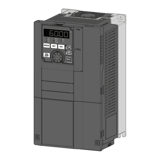
I I n n t t r r o o d d u u c c t t i i o o n n Component Names Figure 1. A820 and A840 models Name Name Symbol Description Symbol Description PU connector Connects the Voltage/current input Selects between... - Page 10 I I n n t t r r o o d d u u c c t t i i o o n n Name Name Symbol Description Symbol Description Power lamp Stays ON while the Front cover (lower Remove this cover for power is supplied to side) wiring.
- Page 11 I I n n t t r r o o d d u u c c t t i i o o n n Figure 2. A860 models Symbol Name Description Symbol Name Description PU connector Connects the EMC filter ON/OFF Turns ON/OFF the EMC operation panel or the connector...
- Page 12 I I n n t t r r o o d d u u c c t t i i o o n n Name Name Symbol Description Symbol Description Operation panel (FR- Operates and monitors Switches for Do not change the DU08) the inverter.
-
Page 13: Installation And Wiring
Installation and Wiring Removal and Reinstallation of Removal and Reinstallation of Front Cover the Operation Panel and Front Covers Removal of the Front Cover (upper side) (FR- A820-01540(30K) or lower, FR-A840-00770 Removal and Reinstallation of Operation (30K) or lower) Panel 1. - Page 14 I I n n s s t t a a l l l l a a t t i i o o n n a a n n d d W W i i r r i i n n g g Reinstallation of the Front Covers (FR-A820- Removal of the front cover (upper side) (FR- 01540(30K) or lower, FR-A840-00770(30K) or...
- Page 15 I I n n s s t t a a l l l l a a t t i i o o n n a a n n d d W W i i r r i i n n g g Removal of the front cover (upper side) (FR- 1.
- Page 16 I I n n s s t t a a l l l l a a t t i i o o n n a a n n d d W W i i r r i i n n g g 3.
-
Page 17: Main Circuit Terminals
I I n n s s t t a a l l l l a a t t i i o o n n a a n n d d W W i i r r i i n n g g Main Circuit Terminals Details on the Main Circuit Terminals Terminal... -
Page 18: And The Motor
I I n n s s t t a a l l l l a a t t i i o o n n a a n n d d W W i i r r i i n n g g Terminal Layout of the Main Circuit Terminals, Wiring of Power Supply and the Motor RT-SVD008B-EN... - Page 19 I I n n s s t t a a l l l l a a t t i i o o n n a a n n d d W W i i r r i i n n g g RT-SVD008B-EN...
- Page 20 I I n n s s t t a a l l l l a a t t i i o o n n a a n n d d W W i i r r i i n n g g RT-SVD008B-EN...
-
Page 21: Control Circuit
I I n n s s t t a a l l l l a a t t i i o o n n a a n n d d W W i i r r i i n n g g Control Circuit N N o o t t e e s s : : •... - Page 22 I I n n s s t t a a l l l l a a t t i i o o n n a a n n d d W W i i r r i i n n g g Table 2.
-
Page 23: External Transistor Connect This Terminal To The Power Supply
I I n n s s t t a a l l l l a a t t i i o o n n a a n n d d W W i i r r i i n n g g Table 2. -
Page 24: Frequency Setting
I I n n s s t t a a l l l l a a t t i i o o n n a a n n d d W W i i r r i i n n g g Table 2. - Page 25 I I n n s s t t a a l l l l a a t t i i o o n n a a n n d d W W i i r r i i n n g g Table 3.
-
Page 26: Frequency Setting
I I n n s s t t a a l l l l a a t t i i o o n n a a n n d d W W i i r r i i n n g g Table 3. -
Page 27: Control Logic (Sink/Source)
I I n n s s t t a a l l l l a a t t i i o o n n a a n n d d W W i i r r i i n n g g Table 5. -
Page 28: Wiring Of Control Circuit
I I n n s s t t a a l l l l a a t t i i o o n n a a n n d d W W i i r r i i n n g g circuit may occur with neighboring wires. -
Page 29: Common Terminals Of The Control
I I n n s s t t a a l l l l a a t t i i o o n n a a n n d d W W i i r r i i n n g g 3. -
Page 30: Wiring Precautions
I I n n s s t t a a l l l l a a t t i i o o n n a a n n d d W W i i r r i i n n g g When Using Separate Power Supplies for the Control and the Main Circuit... -
Page 31: Supplying 24 V External Power To The Control Circuit
I I n n s s t t a a l l l l a a t t i i o o n n a a n n d d W W i i r r i i n n g g FR-A820-00340(5.5K) to FR-A820-00630(11K), N N o o t t e e s s : : FR-A840-00170(5.5K) to FR-A840-00380(15K),... -
Page 32: Operation
I I n n s s t t a a l l l l a a t t i i o o n n a a n n d d W W i i r r i i n n g g Operation while the 24 V External Power Model Manufacturer... -
Page 33: Safety Stop Function
I I n n s s t t a a l l l l a a t t i i o o n n a a n n d d W W i i r r i i n n g g Safety Stop Function N N o o t t e e s s : : •... -
Page 34: Safety Stop Function Operation
I I n n s s t t a a l l l l a a t t i i o o n n a a n n d d W W i i r r i i n n g g Safety Stop Function Operation Output Operation panel... - Page 35 I I n n s s t t a a l l l l a a t t i i o o n n a a n n d d W W i i r r i i n n g g RT-SVD008B-EN...
-
Page 36: Communication Connectors And Terminals
I I n n s s t t a a l l l l a a t t i i o o n n a a n n d d W W i i r r i i n n g g Communication Connectors and USB Connector Terminals... -
Page 37: Rs-485 Terminal Block
I I n n s s t t a a l l l l a a t t i i o o n n a a n n d d W W i i r r i i n n g g current (500 mA or more) flows, USB host error UF (UF Function Description... - Page 38 I I n n s s t t a a l l l l a a t t i i o o n n a a n n d d W W i i r r i i n n g g RT-SVD008B-EN...
-
Page 39: Precautions For Use Of The Inverter
Precautions for Use of the Inverter Electro-magnetic Interference (EMI) and Leakage Currents Built-in EMC Filter This inverter is equipped with a built-in EMC filter (capacitive filter) and a common mode choke. These filters are effective in reducing air-propagated noise on the input side of the inverter. - Page 40 P P r r e e c c a a u u t t i i o o n n s s f f o o r r U U s s e e o o f f t t h h e e I I n n v v e e r r t t e e r r Table 8.
-
Page 41: Basic Operation
Basic Operation Operation Panel (FR-DU08) Components of the Operation Panel (FR-DU08) RT-SVD008B-EN... -
Page 42: Basic Operation
B B a a s s i i c c O O p p e e r r a a t t i i o o n n Basic Operation Operation Function Description panel name indication Clears and resets parameter settings to the initial values. -
Page 43: Changing The Parameter Setting
B B a a s s i i c c O O p p e e r r a a t t i i o o n n Changing the Parameter Setting Monitoring the Inverter Status Value Monitoring of Output Current and Output Voltage Changing Example: the PR.1 Maximum Frequency... -
Page 44: Changing Example
B B a a s s i i c c O O p p e e r r a a t t i i o o n n Changing Example 2. Turn until “7 7 9 9 - - - - 3 3 ” (External/PU combined operation mode 1) appears. -
Page 45: Basic Operation Procedure
B B a a s s i i c c O O p p e e r r a a t t i i o o n n N N o o t t e e s s : : While the value is flickering, press S S E E T T to enter the frequency. -
Page 46: Basic Operation Procedure
B B a a s s i i c c O O p p e e r r a a t t i i o o n n Turn the frequency setting potentiometer clockwise about 3 s of flickering, the indication goes back to slowly to full. -
Page 47: Setting The Frequency With Analog
B B a a s s i i c c O O p p e e r r a a t t i i o o n n Setting the Frequency with Analog Turn the potentiometer (frequency setting potentiometer) clockwise slowly to full. The Signals (voltage input) frequency value on the indication increases in P P r r . -
Page 48: Parameters
Parameters Application-Specific Parameters The tables below show the list of parameters that need to be changed from their default values for specific Each inverter is programmed specifically for the combination of inverter model, compressor model, and variable speed compressor in the system and any system tonnage. - Page 49 P P a a r r a a m m e e t t e e r r s s RT-SVD008B-EN...
- Page 50 P P a a r r a a m m e e t t e e r r s s RT-SVD008B-EN...
- Page 51 P P a a r r a a m m e e t t e e r r s s RT-SVD008B-EN...
- Page 52 P P a a r r a a m m e e t t e e r r s s RT-SVD008B-EN...
- Page 53 P P a a r r a a m m e e t t e e r r s s Table 10. Compressor parameters for ZPV066-7E9 Compressor Model No. ZPV066-7E9 Drive Voltage 480VAC 600VAC Drive Model No. FR-A840-00310-1-TR FR-A860-00320-1-TR Trane Part Number X13171806010 X13171806014 Unit Tonnage...
-
Page 54: Environment Specific Parameters
P P a a r r a a m m e e t t e e r r s s Table 10. Compressor parameters for ZPV066-7E9 (continued) Compressor Model No. ZPV066-7E9 Drive Voltage 480VAC 600VAC Drive Model No. FR-A840-00310-1-TR FR-A860-00320-1-TR Trane Part Number X13171806010 X13171806014... - Page 55 P P a a r r a a m m e e t t e e r r s s N N o o t t e e : : Pr.77 can be set at any time regardless of the Name operation mode or operation status.
- Page 56 P P a a r r a a m m e e t t e e r r s s Name Name PU buzzer control Torque command value (RAM, EEPROM) PU contrast adjustment Fault initiation Writing during operation is disabled. To change the parameter setting Operation panel setting dial push monitor selection value, stop the operation.
-
Page 57: Password Function
P P a a r r a a m m e e t t e e r r s s Name Name 313 to 738 to (Extended output terminal function selection) (Second PM motor tuning) Digital input unit selection Second motor low-speed range torque characteristic selection Resolver position tuning setting/status Low speed range torque characteristic selection... - Page 58 P P a a r r a a m m e e t t e e r r s s Setting When Pr.297 = "0, 9999", writing is always enabled, but setting is Initial Description Name disabled. (The display cannot be changed.) range value Note: The above parameters can be set when Pr.160 User group...
- Page 59 P P a a r r a a m m e e t t e e r r s s Parameter Reading/Writing Restriction Level (Pr.296) The level of the reading/writing restriction using the PU/Network (NET) operation mode operation command can be selected with Pr.296. NET operation mode operation command PU operation mode operation RS-485 terminals / PLC function...
- Page 60 P P a a r r a a m m e e t t e e r r s s unlocked even if the correct password is subsequently N N o o t t e e s s : : input.
-
Page 61: Multiple Rating Setting
P P a a r r a a m m e e t t e e r r s s N N o o t t e e s s : : parameter unit, and USB memory is not enabled. •... - Page 62 P P a a r r a a m m e e t t e e r r s s Pr.570 setting (Initial value) Name Stall prevention operation level for 110% 120% 150% 200% restart Current average value monitor signal output SLD rated current (a)*2 LD rated current...
- Page 63 P P a a r r a a m m e e t t e e r r s s RT-SVD008B-EN...
-
Page 64: Operation Command And Frequency
P P a a r r a a m m e e t t e e r r s s Operation Command and Network operation (when RS-485 terminals or a communication option is used). Frequency Command Pr.: 79 D000. Operation Mode Selection Name: Operation mode selection. -
Page 65: Protective Function Parameter
P P a a r r a a m m e e t t e e r r s s Operation Mode Switching Method Protective Function Parameter The operation mode can be selected from the Motor Overheat Protection (electronic operation panel or with the communication instruction thermal O/L relay) code. - Page 66 P P a a r r a a m m e e t t e e r r s s Setting range Description Name Initial value 9999 0 to 590 Hz The electronic thermal O/L relay operation level can be Second free thermal reduction H011 frequency 1...
-
Page 67: Retry Function
P P a a r r a a m m e e t t e e r r s s N N o o t t e e s s : : MM-CF • The internal accumulated heat value of the electronic thermal relay function is reset to the initial value by the inverter's power reset and reset signal input. -
Page 68: Multi-Function Input Terminal
P P a a r r a a m m e e t t e e r r s s Setting range Description Name Initial value A retry-making fault can be selected. (Refer to the table on the Retry selection 0 to 5 next page.) H300... - Page 69 P P a a r r a a m m e e t t e e r r s s Initial Setting range Name Description value The terminal 2 input specification (0 to 5 V, 0 Switch 1 - OFF (initial to 10 V, 0 to 20 mA) and terminal 1 input 0 to 5, 10 to 15 status)
- Page 70 P P a a r r a a m m e e t t e e r r s s Compensation input terminal Terminal 2 Terminal 1 compensation Pr.73 setting input input Polarity reversible Switch 1 method 0 to 10 V 0 to ±10 V 1 (initial value) 0 to 5 V...
- Page 71 P P a a r r a a m m e e t t e e r r s s N N o o t t e e s s : : • To enable the terminal 4, turn the AU signal •...
-
Page 72: Application Parameters
P P a a r r a a m m e e t t e e r r s s available by setting the regulator output signal 4 to 20 Setting "6, 7, 16, or 17" in Pr.73 and turning the voltage/ mADC to between terminals 4 and 5. - Page 73 P P a a r r a a m m e e t t e e r r s s Setting Description Name Initial value range Unit scale factor 0: No function 1: ´1 Pre-scale function 0 to 5 When the pulse train is input from terminal JOG, 2: ´0.1 A802 selection...
-
Page 74: Trace Function
P P a a r r a a m m e e t t e e r r s s Copying the PLC Function Project Data to Copy from Copy from inverter to USB Memory memory to This function copies the PLC function project data to a File type memory inverter... - Page 75 P P a a r r a a m m e e t t e e r r s s Setting Initial range Description Name value Manual sampling start 1024 Sampling auto start A904 Sampling starts automatically when the power supply is turned ON or at a reset 1025 Fault trigger...
- Page 76 P P a a r r a a m m e e t t e e r r s s Setting Initial range Description Name value Digital source selection 1038 (1ch) A930 Digital source selection 1039 (2ch) A931 Digital source selection 1040 (3ch) A932...
- Page 77 P P a a r r a a m m e e t t e e r r s s N N o o t t e e s s : : Trigger Monitored Minus sign Setting level • When the trace function is used in the item display value...
- Page 78 P P a a r r a a m m e e t t e e r r s s Trigger Trigger Monitored Minus sign Monitored Minus sign Setting Setting level level item display item display value value criterion criterion Motor *Output ND rated...
- Page 79 P P a a r r a a m m e e t t e e r r s s Trigger Setting Signal Monitored Minus sign Remarks Setting level value name item display value criterion Cumulative pulse overflow times Cumulative pulse (control terminal option) "*"...
- Page 80 P P a a r r a a m m e e t t e e r r s s To automatically start sampling when the power Selection of trigger supply is turned ON or at a recovery after an inverter r.1025 Trigger generating target...
-
Page 81: Operation Via Communication And Its
P P a a r r a a m m e e t t e e r r s s Trace status Monitor value 1000s place 100s place 10s place 1s place 0 or no display No trace data in internal USB memory not accessed Trigger not detected Trace stopped... - Page 82 P P a a r r a a m m e e t t e e r r s s Connection of RS-485 Terminals and Wires N N o o t t e e s s : : The size of RS-485 terminal block is the same as the •...
-
Page 83: Usb Device Communication
P P a a r r a a m m e e t t e e r r s s How to Wire RS-485 Terminals Two-Wire Type Connection N N o o t t e e : : A program should be created so that transmission is disabled (receiving state) when If the computer is 2-wire type, a connection from the the computer is not sending and reception is... -
Page 84: Copying And Verifying Parameters On
P P a a r r a a m m e e t t e e r r s s Setting Initial range Description Name value USB communication N040 Inverter station number specification 0 to 31 station number USB communication is possible, however the inverter will trip (E. USB) when the mode changes to the PU operation mode. -
Page 85: Parameter Copy
P P a a r r a a m m e e t t e e r r s s Parameter Copy 7. When parameters are written to the destination inverter, reset the inverter before operation by, for Inverter parameter settings can be copied to other example, turning the power supply OFF. -
Page 86: Copying And Verifying Parameters Using
P P a a r r a a m m e e t t e e r r s s Copying and Verifying Turn the dial to change setting value “3 3 . . v v F F Y Y ” (parameter copy verification mode.) Parameters using USB Memory Press S S E E T T Verification of the parameter settings... -
Page 87: Procedure For Copying Parameters To
P P a a r r a a m m e e t t e e r r s s N N o o t t e e s s : : about 15 seconds to copy all the settings. During copying, “2 2 . -
Page 88: Procedure For Verifying Parameters
P P a a r r a a m m e e t t e e r r s s Procedure for Verifying Parameters in 1. Turning ON the power of the inverter. USB Memory The monitor display turns ON. 2. -
Page 89: Protective Functions
Protective Functions Inverter Fault and Alarm N N o o t t e e : : The past eight faults can be displayed on the operation panel. (Faults history) Indications Reset Method for the Protective When a problem arises with the inverter, it be diagnosed with the instructions outlined in this section. -
Page 90: Check For The Faults History
P P r r o o t t e e c c t t i i v v e e F F u u n n c c t t i i o o n n s s Check for the Faults History Faults History Clearing Procedure 3. -
Page 91: List Of Fault Displays
P P r r o o t t e e c c t t i i v v e e F F u u n n c c t t i i o o n n s s • Press S S E E T T to show the setting again. Operation panel •... - Page 92 P P r r o o t t e e c c t t i i v v e e F F u u n n c c t t i i o o n n s s Operation Operation panel Data panel...
-
Page 93: Causes And Corrective Actions
P P r r o o t t e e c c t t i i v v e e F F u u n n c c t t i i o o n n s s Operation Operation panel Data panel... - Page 94 P P r r o o t t e e c c t t i i v v e e F F u u n n c c t t i i o o n n s s Operation Operation panel panel indication...
-
Page 95: Warning
P P r r o o t t e e c c t t i i v v e e F F u u n n c c t t i i o o n n s s Operation Operation panel panel indication... - Page 96 P P r r o o t t e e c c t t i i v v e e F F u u n n c c t t i i o o n n s s Operation panel FR-LU08 indication Stall prevention (overcurrent)
- Page 97 P P r r o o t t e e c c t t i i v v e e F F u u n n c c t t i i o o n n s s Operation panel indication FR-LU08 Regenerative brake pre-alarm (Standard models only)
- Page 98 P P r r o o t t e e c c t t i i v v e e F F u u n n c c t t i i o o n n s s Operation panel indication FR-LU08 Parameter copy...
-
Page 99: Alarm
P P r r o o t t e e c c t t i i v v e e F F u u n n c c t t i i o o n n s s Operation panel indication HP1 to HP3 FR-LU08... - Page 100 P P r r o o t t e e c c t t i i v v e e F F u u n n c c t t i i o o n n s s Operation panel OC During Acc indication E.OC1...
- Page 101 P P r r o o t t e e c c t t i i v v e e F F u u n n c c t t i i o o n n s s Operation panel Stedy Spd OC indication E.OC2...
- Page 102 P P r r o o t t e e c c t t i i v v e e F F u u n n c c t t i i o o n n s s Differs according to ratings. The rating can be changed using Pr.570 Multiple rating setting. 148% for SLD rating, 170% for LD rating, 235% for ND rating (initial setting), and 280% for HD rating.
- Page 103 P P r r o o t t e e c c t t i i v v e e F F u u n n c c t t i i o o n n s s Operation panel indication E.THT FR-LU08...
- Page 104 P P r r o o t t e e c c t t i i v v e e F F u u n n c c t t i i o o n n s s Operation panel indication FR-LU08 Inst.
- Page 105 P P r r o o t t e e c c t t i i v v e e F F u u n n c c t t i i o o n n s s Operation panel indication E.OLT FR-LU08...
- Page 106 P P r r o o t t e e c c t t i i v v e e F F u u n n c c t t i i o o n n s s Operation panel Output phase loss indication FR-LU08...
- Page 107 P P r r o o t t e e c c t t i i v v e e F F u u n n c c t t i i o o n n s s Operation panel Option Fault indication E.OPT...
- Page 108 P P r r o o t t e e c c t t i i v v e e F F u u n n c c t t i i o o n n s s Operation panel indication E.16 to E.20 FR-LU08...
- Page 109 P P r r o o t t e e c c t t i i v v e e F F u u n n c c t t i i o o n n s s E.CPU CPU Fault Fault 5 Fault 6 Operation...
- Page 110 P P r r o o t t e e c c t t i i v v e e F F u u n n c c t t i i o o n n s s Operation panel indication E.CDO FR-LU08...
- Page 111 P P r r o o t t e e c c t t i i v v e e F F u u n n c c t t i i o o n n s s Operation panel Safety circuit fault indication E.SAF...
- Page 112 P P r r o o t t e e c c t t i i v v e e F F u u n n c c t t i i o o n n s s Operation panel E.OSD Sped deviation fault indication...
- Page 113 P P r r o o t t e e c c t t i i v v e e F F u u n n c c t t i i o o n n s s Operation panel indication E.MB1 to 7 FR-LU08...
- Page 114 P P r r o o t t e e c c t t i i v v e e F F u u n n c c t t i i o o n n s s Operation panel Lost mA Input indication E.LCI...
-
Page 115: Cable Size For The Control Circuit Power Supply
P P r r o o t t e e c c t t i i v v e e F F u u n n c c t t i i o o n n s s Operation panel indication E.1 to E.3 FR-LU08... -
Page 116: Motor Does Not Start
P P r r o o t t e e c c t t i i v v e e F F u u n n c c t t i i o o n n s s Motor does not Start Check points Possible cause Countermeasure... - Page 117 P P r r o o t t e e c c t t i i v v e e F F u u n n c c t t i i o o n n s s Check points Possible cause Countermeasure Check the start command source, and input a start signal.
- Page 118 P P r r o o t t e e c c t t i i v v e e F F u u n n c c t t i i o o n n s s Check points Possible cause Countermeasure Increase the Pr.0 setting by 0.5% increments while observing the...
-
Page 119: Abnormal Noise
P P r r o o t t e e c c t t i i v v e e F F u u n n c c t t i i o o n n s s Check points Possible cause Countermeasure Set Pr.599="0"... -
Page 120: Abnormally
P P r r o o t t e e c c t t i i v v e e F F u u n n c c t t i i o o n n s s Motor Generates Heat Abnormally Check points Possible cause Countermeasure... -
Page 121: Smooth
P P r r o o t t e e c c t t i i v v e e F F u u n n c c t t i i o o n n s s Acceleration/Deceleration is not Smooth Check points Possible cause Countermeasure... -
Page 122: Properly
P P r r o o t t e e c c t t i i v v e e F F u u n n c c t t i i o o n n s s Check points Possible cause Countermeasure Fluctuation of power supply voltage is too... -
Page 123: Motor Current Is Too Large
P P r r o o t t e e c c t t i i v v e e F F u u n n c c t t i i o o n n s s Motor Current is too Large Check points Possible cause Countermeasure... -
Page 124: Speed Does Not Accelerate
P P r r o o t t e e c c t t i i v v e e F F u u n n c c t t i i o o n n s s Speed does not Accelerate Check points Possible cause Countermeasure... -
Page 125: Unable To Write Parameter
P P r r o o t t e e c c t t i i v v e e F F u u n n c c t t i i o o n n s s Unable to Write Parameter Setting Check points Possible cause Countermeasure... -
Page 126: Precautions For Maintenance And Inspection
Precautions for Maintenance and Inspection The inverter is a static unit mainly consisting of • Abnormal vibration, abnormal noise semiconductor devices. Daily inspection must be • Abnormal overheat, discoloration performed to prevent any fault from occurring due to the adverse effects of the operating environment, such Periodic Inspection as temperature, humidity, dust, dirt and vibration, Check the areas inaccessible during operation and... - Page 127 P P r r e e c c a a u u t t i i o o n n s s f f o o r r M M a a i i n n t t e e n n a a n n c c e e a a n n d d I I n n s s p p e e c c t t i i o o n n Inspection Interval Area of...
-
Page 128: Checking The Inverter And Converter
P P r r e e c c a a u u t t i i o o n n s s f f o o r r M M a a i i n n t t e e n n a a n n c c e e a a n n d d I I n n s s p p e e c c t t i i o o n n Inspection Interval Area of... -
Page 129: Inverter Replacement
P P r r e e c c a a u u t t i i o o n n s s f f o o r r M M a a i i n n t t e e n n a a n n c c e e a a n n d d I I n n s s p p e e c c t t i i o o n n Module Device Numbers and Terminals to be Checked Inverter Replacement commercial frequency are used for measurement,... -
Page 130: Instruments
P P r r e e c c a a u u t t i i o o n n s s f f o o r r M M a a i i n n t t e e n n a a n n c c e e a a n n d d I I n n s s p p e e c c t t i i o o n n Measuring Points and Instruments Measuring point Measuring instrument... -
Page 131: Measurement Of Powers
P P r r e e c c a a u u t t i i o o n n s s f f o o r r M M a a i i n n t t e e n n a a n n c c e e a a n n d d I I n n s s p p e e c c t t i i o o n n Measuring point Measuring instrument Remarks (reference measured value) -
Page 132: Measurement Of Voltages And Use Of
P P r r e e c c a a u u t t i i o o n n s s f f o o r r M M a a i i n n t t e e n n a a n n c c e e a a n n d d I I n n s s p p e e c c t t i i o o n n Measurement of Voltages and Use of PT Measurement conditions Inverter Input Side... -
Page 133: Insulation Resistance Test Using
P P r r e e c c a a u u t t i i o o n n s s f f o o r r M M a a i i n n t t e e n n a a n n c c e e a a n n d d I I n n s s p p e e c c t t i i o o n n Pressure Test across the analog current output terminals CA and 5 of the inverter. -
Page 134: Specification
Specification Inverter Rating 200 V Class RT-SVD008B-EN... -
Page 135: Class
S S p p e e c c i i f f i i c c a a t t i i o o n n 400 V Class RT-SVD008B-EN... -
Page 136: 600 V Class
S S p p e e c c i i f f i i c c a a t t i i o o n n 600 V Class FR-A860–00450 or Lower RT-SVD008B-EN... - Page 137 S S p p e e c c i i f f i i c c a a t t i i o o n n FR-A860–00680 or Higher RT-SVD008B-EN...
-
Page 138: Common Specifications
S S p p e e c c i i f f i i c c a a t t i i o o n n Common Specifications Soft-PWM control, high carrier frequency PWM control (selectable among V/F control, Control method Advanced magnetic flux vector control, Real sensorless vector control), vector control and PM sensorless vector control 0.2 to 590 Hz (The upper-limit frequency is 400 Hz under Advanced magnetic flux vector... - Page 139 S S p p e e c c i i f f i i c c a a t t i i o o n n Analog Terminals 2 and 4: 0 to 10 V, 0 to 5 V, 4 to 20 mA (0 to 20 mA) are available. Terminal 1: input -10 to +10 V, -5 to +5 V are available.
- Page 140 S S p p e e c c i i f f i i c c a a t t i i o o n n Overcurrent trip during acceleration, Overcurrent trip during constant speed, Overcurrent trip during deceleration or stop, Regenerative overvoltage trip during acceleration, Regenerative overvoltage trip during constant speed, Regenerative overvoltage trip during deceleration or stop, Inverter overload trip, Motor overload trip, Heatsink overheat, Instantaneous power failure...
-
Page 141: Outline Dimension Drawings
S S p p e e c c i i f f i i c c a a t t i i o o n n Outline Dimension Drawings Inverter Outline Dimension Drawings F F R R - - A A 8 8 2 2 0 0 - - 0 0 0 0 0 0 4 4 6 6 ( ( 0 0 . . 4 4 K K ) ) , , F F R R - - A A 8 8 2 2 0 0 - - 0 0 0 0 0 0 7 7 7 7 ( ( 0 0 . . 7 7 5 5 K K ) ) F F R R - - A A 8 8 2 2 0 0 - - 0 0 0 0 1 1 0 0 5 5 ( ( 1 1 . - Page 142 S S p p e e c c i i f f i i c c a a t t i i o o n n F F R R - - A A 8 8 2 2 0 0 - - 0 0 0 0 3 3 4 4 0 0 ( ( 5 5 . . 5 5 K K ) ) , , 0 0 0 0 4 4 9 9 0 0 ( ( 7 7 . . 5 5 K K ) ) , , 0 0 0 0 6 6 3 3 0 0 ( ( 1 1 1 1 K K ) ) F F R R - - A A 8 8 6 6 0 0 –...
- Page 143 S S p p e e c c i i f f i i c c a a t t i i o o n n F F R R - - A A 8 8 2 2 0 0 - - 0 0 1 1 5 5 4 4 0 0 ( ( 3 3 0 0 K K ) ) F F R R - - A A 8 8 4 4 0 0 - - 0 0 0 0 7 7 7 7 0 0 ( ( 3 3 0 0 K K ) ) RT-SVD008B-EN...
- Page 144 S S p p e e c c i i f f i i c c a a t t i i o o n n F F R R - - A A 8 8 2 2 0 0 - - 0 0 1 1 8 8 7 7 0 0 ( ( 3 3 7 7 K K ) ) , , 0 0 2 2 3 3 3 3 0 0 ( ( 4 4 5 5 K K ) ) , , 0 0 3 3 1 1 6 6 0 0 ( ( 5 5 5 5 K K ) ) , , F F R R - - A A 8 8 4 4 0 0 - - 0 0 0 0 9 9 3 3 0 0 ( ( 3 3 7 7 K K ) ) , , 0 0 1 1 1 1 6 6 0 0 ( ( 4 4 5 5 K K ) ) , , 0 0 1 1 8 8 0 0 0 0 ( ( 5 5 5 5 K K ) ) , , 0 0 3 3 8 8 0 0 0 0 ( ( 7 7 5 5 K K ) ) , , 0 0 4 4 7 7 5 5 0 0 ( ( 9 9 0 0 K K ) ) 0 0 2 2 1 1 6 6 0 0 ( ( 7 7 5 5 K K ) ) , , 0 0 2 2 6 6 0 0 0 0 ( ( 9 9 0 0 K K ) ) , , 0 0 3 3 2 2 5 5 0 0 ( ( 1 1 1 1 0 0 K K ) ) , , 0 0 3 3 6 6 1 1 0 0 ( ( 1 1 3 3 2 2 K K ) )
- Page 145 S S p p e e c c i i f f i i c c a a t t i i o o n n F F R R - - A A 8 8 6 6 0 0 – – 0 0 2 2 8 8 9 9 0 0 , , 0 0 3 3 3 3 6 6 0 0 , , F F R R - - A A 8 8 4 4 0 0 - - 0 0 4 4 3 3 2 2 0 0 ( ( 1 1 6 6 0 0 K K ) ) , , 0 0 4 4 8 8 1 1 0 0 ( ( 1 1 8 8 5 5 K K ) ) RT-SVD008B-EN...
- Page 146 S S p p e e c c i i f f i i c c a a t t i i o o n n F F R R - - 0 0 8 8 6 6 0 0 – – 0 0 4 4 4 4 2 2 0 0 , , F F R R - - A A 8 8 4 4 0 0 - - 0 0 5 5 4 4 7 7 0 0 ( ( 2 2 2 2 0 0 K K ) ) , , 0 0 6 6 1 1 0 0 0 0 ( ( 2 2 5 5 0 0 K K ) ) , , 0 0 6 6 8 8 3 3 0 0 ( ( 2 2 8 8 0 0 K K ) ) RT-SVD008B-EN...
- Page 147 S S p p e e c c i i f f i i c c a a t t i i o o n n O O p p e e r r a a t t i i o o n n p p a a n n e e l l ( ( F F R R - - D D U U 0 0 8 8 ) ) RT-SVD008B-EN...
-
Page 148: Relevant Manuals And Hardware
Appendix A. Relevant Manuals and Hardware Relevant Manuals – IB(NA)-0600505-A — FR-A8AP PLG/Encoder Instruction Manual – IB(NA)-0600509-A — FR-A8NCE CC-Link IE Field • A800 Instruction Manual – IB(NA)-0600503-G — A800 Instruction Manual – IB(NA)-0600511-A — FR-A8ND DeviceNet (detailed) Instruction Manual –... - Page 149 N N o o t t e e s s RT-SVD008B-EN...
- Page 150 N N o o t t e e s s RT-SVD008B-EN...
- Page 151 N N o o t t e e s s RT-SVD008B-EN...
- Page 152 Ingersoll Rand (NYSE: IR) advances the quality of life by creating comfortable, sustainable and efficient environments. Our people and our family of brands — including Club Car ® , Ingersoll Rand ® , Thermo King ® Trane ® — work together to enhance the quality and comfort of air in homes and buildings; transport and protect food and perishables;...
Need help?
Do you have a question about the Precedent eFlex TZC072F3 and is the answer not in the manual?
Questions and answers