Table of Contents
Advertisement
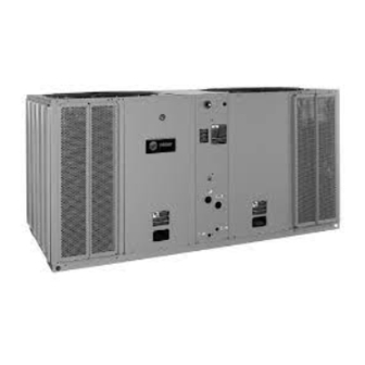
Installation, Operation,
and Maintenance
Split System Air Conditioners
Odyssey™ ™
Cooling Condenser — 6 to 25 Tons
( ( 6 6 0 0 H H z z ) )
TTA073G/H***A
TTA090G/H***A
TTA120G/H/J***A
TTA150H***A
TTA180H/J***A
TTA240H/J***A
TTA300J***A
Only qualified personnel should install and service the equipment. The installation, starting up, and servicing of heating, ventilating, and
air-conditioning equipment can be hazardous and requires specific knowledge and training. Improperly installed, adjusted or altered
equipment by an unqualified person could result in death or serious injury. When working on the equipment, observe all precautions in the
literature and on the tags, stickers, and labels that are attached to the equipment.
September 2016
( ( 5 5 0 0 H H z z ) )
TTA061G/H***A
TTA076G/H***A
TTA101G/H/J***A
TTA126H***A
TTA156H/J***A
TTA201H/J***A
TTA251J***A
S S A A F F E E T T Y Y W W A A R R N N I I N N G G
SS-SVX10H-EN
Advertisement
Table of Contents

Related Manuals for Ingersoll-Rand Odyssey TTA073G A Series


Summary of Contents for Ingersoll-Rand Odyssey TTA073G A Series
- Page 1 Installation, Operation, and Maintenance Split System Air Conditioners Odyssey™ ™ Cooling Condenser — 6 to 25 Tons ( ( 6 6 0 0 H H z z ) ) ( ( 5 5 0 0 H H z z ) ) TTA073G/H***A TTA061G/H***A TTA090G/H***A...
- Page 2 Introduction Read this manual thoroughly before operating or W W A A R R N N I I N N G G servicing this unit. P P r r o o p p e e r r F F i i e e l l d d W W i i r r i i n n g g a a n n d d G G r r o o u u n n d d i i n n g g R R e e q q u u i i r r e e d d ! ! Warnings, Cautions, and Notices F F a a i i l l u u r r e e t t o o f f o o l l l l o o w w c c o o d d e e c c o o u u l l d d r r e e s s u u l l t t i i n n d d e e a a t t h h o o r r...
- Page 3 I I n n t t r r o o d d u u c c t t i i o o n n W W A A R R N N I I N N G G W W A A R R N N I I N N G G E E x x p p l l o o s s i i o o n n H H a a z z a a r r d d ! ! R R e e f f r r i i g g e e r r a a n n t t u u n n d d e e r r H H i i g g h h P P r r e e s s s s u u r r e e ! ! F F a a i i l l u u r r e e t t o o f f o o l l l l o o w w i i n n s s t t r r u u c c t t i i o o n n s s b b e e l l o o w w c c o o u u l l d d r r e e s s u u l l t t i i n n...
-
Page 4: Table Of Contents
Table of Contents Model Number Description ....6 Pre-Start ........43 Cooling Condenser . - Page 5 T T a a b b l l e e o o f f C C o o n n t t e e n n t t s s Method 1 ......50 Annually (Cooling Season) .
-
Page 6: Model Number Description
Model Number Description Cooling Condenser T T A 2 40 1 2 3 4 5 6 9 10 N N o o t t e e : : When ordering replacement parts or requesting D D I I G G I I T T 8 8 : : E E l l e e c c t t r r i i c c a a l l C C h h a a r r a a c c t t e e r r i i s s t t i i c c s s service, be sure to refer to the specific model 3 = 208–230/60/3 number, serial number, and DL number (if... -
Page 7: General Information
General Information N N o o t t e e : : It is not the intention of this manual to cover all This manual describes proper installation, operation, possible variations in systems that may occur or and maintenance procedures for air-cooled systems. By carefully reviewing the information within this manual to provide comprehensive information and following the instructions, the risk of improper... -
Page 8: Pre-Installation
Pre-Installation Unit Inspection Lifting Recommendations Inspect material carefully for any shipping damage. If W W A A R R N N I I N N G G damaged, it must be reported to, and claims made I I m m p p r r o o p p e e r r U U n n i i t t L L i i f f t t ! ! against the transportation company. -
Page 9: Unit Mounting
P P r r e e - - I I n n s s t t a a l l l l a a t t i i o o n n Unit Mounting Figure 1. Roof mounted unit W W A A R R N N I I N N G G M M o o u u n n t t i i n n g g I I n n t t e e g g r r i i t t y y ! ! F F a a i i l l u u r r e e t t o o f f o o l l l l o o w w i i n n s s t t r r u u c c t t i i o o n n b b e e l l o o w w c c o o u u l l d d r r e e s s u u l l t t i i n n d d e e a a t t h h o o r r s s e e r r i i o o u u s s i i n n j j u u r r y y o o r r p p o o s s s s i i b b l l e e e e q q u u i i p p m m e e n n t t o o r r... -
Page 10: Dimensional Data
Dimensional Data Figure 2. Height, width and depth measurements H - in. (mm) W - in. (mm) D - in. (mm) TTA061, 073, 076, 090 46.1 (1171) 45 (1143) 38 (965.2) TTA101, 120 46.1 (1171) 55 (1397) 42 (1067) TTA126, 150 52.1 (1323) 55 (1397) 42 (1067) - Page 11 D D i i m m e e n n s s i i o o n n a a l l D D a a t t a a Figure 3. 5, 6, 6.25 and 7.5 ton condensing unit, single compressor, microchannel SS-SVX10H-EN...
- Page 12 D D i i m m e e n n s s i i o o n n a a l l D D a a t t a a Figure 4. 5, 6, 6.25 and 7.5 ton condensing unit, dual compressor, microchannel SS-SVX10H-EN...
- Page 13 D D i i m m e e n n s s i i o o n n a a l l D D a a t t a a Figure 5. 8.33 and 10 ton condensing unit, single and manifolded compressor. microchannel SS-SVX10H-EN...
- Page 14 D D i i m m e e n n s s i i o o n n a a l l D D a a t t a a Figure 6. 8.33 and 10 ton condensing unit, dual compressor, microchannel SS-SVX10H-EN...
- Page 15 D D i i m m e e n n s s i i o o n n a a l l D D a a t t a a Figure 7. 10.4 and 12.5 ton condensing unit, dual compressor, microchannel SS-SVX10H-EN...
- Page 16 D D i i m m e e n n s s i i o o n n a a l l D D a a t t a a Figure 8. 13, 15, 16.7 and 20 ton condensing unit, dual compressor, microchannel SS-SVX10H-EN...
- Page 17 D D i i m m e e n n s s i i o o n n a a l l D D a a t t a a Figure 9. 13, 15, 16.7 and 20 condensing unit, manifolded compressor, microchannel SS-SVX10H-EN...
- Page 18 D D i i m m e e n n s s i i o o n n a a l l D D a a t t a a Figure 10. 20.9 and 25 ton condensing unit, manifolded compressor, microchannel SS-SVX10H-EN...
-
Page 19: Weights
Weights Cooling Condenser Table 1. TTA unit and corner weights — lbs (60 Hz) Corner Weights Net Max Shipping Tons Model No. Max (lbs) (lbs) TTA073G TTA073H TTA090G TTA090H TTA120G TTA120H TTA120J 12.5 TTA150H TTA180H TTA180J TTA240H TTA240J TTA300J Table 2. TTA unit and corner weights — lbs (50 Hz) Corner Weights Net Max Shipping... - Page 20 W W e e i i g g h h t t s s Figure 11. TTA073, 090, 120, 150, TTA061, 076, 101 Figure 12. TTA180, 240, 300, TTA156, 201, 251 SS-SVX10H-EN...
-
Page 21: Installation
Installation Refrigerant Piping Guidelines Figure 13. Allowable elevation difference: TTA above indoor unit Figure 14. Allowable elevation difference: TTA or TWA below indoor unit N N o o t t e e : : Route refrigerant piping for minimum linear length, minimum number of bends and fittings. SS-SVX10H-EN... -
Page 22: Refrigerant Piping Procedures
I I n n s s t t a a l l l l a a t t i i o o n n Refrigerant Piping Procedures Figure 15. Outdoor units - refrigerant piping (with dry nitrogen) (Outdoor Units) W W A A R R N N I I N N G G R R - - 4 4 1 1 0 0 A A R R e e f f r r i i g g e e r r a a n n t t u u n n d d e e r r H H i i g g h h e e r r P P r r e e s s s s u u r r e e t t h h a a n n R R - - 2 2 2 2 ! ! F F a a i i l l u u r r e e t t o o u u s s e e p p r r o o p p e e r r e e q q u u i i p p m m e e n n t t o o r r c c o o m m p p o o n n e e n n t t s s a a s s... -
Page 23: Refrigerant Piping Procedures
I I n n s s t t a a l l l l a a t t i i o o n n and work toward the indoor unit. See 4. Open the gauge port on the suction line and then recommended tube sizes, . -
Page 24: Insulating And Isolating Refrigerant
I I n n s s t t a a l l l l a a t t i i o o n n N N O O T T I I C C E E N N O O T T I I C C E E O O p p e e r r a a t t i i n n g g U U n n d d e e r r V V a a c c u u u u m m ! ! E E q q u u i i p p m m e e n n t t D D a a m m a a g g e e ! ! T T h h i i s s i i s s P P O O E E o o i i l l , , w w h h i i c c h h r r e e a a d d i i l l y y a a b b s s o o r r b b s s m m o o i i s s t t u u r r e e . -
Page 25: Charging Levels
I I n n s s t t a a l l l l a a t t i i o o n n Charging Levels Figure 16. Outdoor units - refrigerant piping Table 4. Estimated charge levels at ARI rated line lengths (25 feet) - 50 & 60 Hz Refrigerant Charge Per Circuit Liquid Line Diameter... - Page 26 I I n n s s t t a a l l l l a a t t i i o o n n Table 4. Estimated charge levels at ARI rated line lengths (25 feet) - 50 & 60 Hz (continued) Refrigerant Charge Per Circuit Liquid Line Diameter...
-
Page 27: Liquid Charging
I I n n s s t t a a l l l l a a t t i i o o n n Figure 18. TTA251, 300 rear refrigerant and electrical connections Liquid Charging cooling to ensure the unit is operating properly. 4. -
Page 28: Electrical Wiring
I I n n s s t t a a l l l l a a t t i i o o n n Electrical Wiring N N O O T T I I C C E E U U s s e e C C o o p p p p e e r r C C o o n n d d u u c c t t o o r r s s O O n n l l y y ! ! W W A A R R N N I I N N G G F F a a i i l l u u r r e e t t o o u u s s e e c c o o p p p p e e r r c c o o n n d d u u c c t t o o r r s s c c o o u u l l d d r r e e s s u u l l t t i i n n P P r r o o p p e e r r F F i i e e l l d d W W i i r r i i n n g g a a n n d d G G r r o o u u n n d d i i n n g g... -
Page 29: Field Wiring
I I n n s s t t a a l l l l a a t t i i o o n n N N o o t t e e s s : : Figure 20. ReliaTel jobsite connections 1. - Page 30 I I n n s s t t a a l l l l a a t t i i o o n n Figure 22. Zone sensor field wiring Figure 23. Thermostat field wiring SS-SVX10H-EN...
- Page 31 I I n n s s t t a a l l l l a a t t i i o o n n Figure 24. Thermostat wiring for electromechanical units SS-SVX10H-EN...
-
Page 32: Refrigerant Circuit
I I n n s s t t a a l l l l a a t t i i o o n n Refrigerant Circuit Figure 25. Typical split system cooling refrigerant circuit — microchannel SS-SVX10H-EN... -
Page 33: Electrical Data
Electrical Data Table 5. Electrical characteristics — compressor and condenser fan motors — 60 Hz Compressor Motor Condenser Fan Motor Unit Amps Amps Tons Model Volts Phase Volts Phase Number (Ea.) (Ea.) (Ea.) (Ea.) TTA073G3 208-230 21.9 208-230 TTA073G4 66.1 TTA073GK 10.3 TTA073GW... - Page 34 E E l l e e c c t t r r i i c c a a l l D D a a t t a a Table 5. Electrical characteristics — compressor and condenser fan motors — 60 Hz (continued) Compressor Motor Condenser Fan Motor Unit...
- Page 35 E E l l e e c c t t r r i i c c a a l l D D a a t t a a Table 6. Unit wiring — condensing units — 60 Hz (continued) Unit Operating Maximum Fuse or HACR Minimum Circuit Ampacity Tons...
- Page 36 E E l l e e c c t t r r i i c c a a l l D D a a t t a a Table 8. Unit wiring — condensing units — 50 Hz Maximum Maximum Fuse Unit Operating Circuit Unit Model...
-
Page 37: Charging Charts And Superheat
Charging Charts and Superheat Figure 26. TTA061G Figure 29. TTA073H Figure 27. TTA061H Figure 30. TTA076G Figure 28. TTA073G Figure 31. TTA076H SS-SVX10H-EN... - Page 38 C C h h a a r r g g i i n n g g C C h h a a r r t t s s a a n n d d S S u u p p e e r r h h e e a a t t Figure 32.
- Page 39 C C h h a a r r g g i i n n g g C C h h a a r r t t s s a a n n d d S S u u p p e e r r h h e e a a t t Figure 40.
- Page 40 C C h h a a r r g g i i n n g g C C h h a a r r t t s s a a n n d d S S u u p p e e r r h h e e a a t t Figure 46.
- Page 41 C C h h a a r r g g i i n n g g C C h h a a r r t t s s a a n n d d S S u u p p e e r r h h e e a a t t Table 9.
-
Page 42: Installation Checklist
Installation Checklist Complete this checklist once the unit is installed to Insulated the entire suction line? verify that all recommended procedures have been Insulated portions of liquid line exposed to accomplished before starting the system. Do not extremes in temperature? operate the system until all items covered by this Performed initial leak test? checklist are complete. -
Page 43: Pre-Start
Pre-Start Control Circuit Features drops below the Low Pressure Cut-Out setting. Once the suction pressure has returned to normal, the N N o o t t e e : : Not all of these features may be required for your compressor and outdoor fans will cycle back on. -
Page 44: Start-Up
Start-Up Electromechanical Controls evaporator fan contactor also energizes on a call for cooling and initiates evaporator fan operation. The 24–volt, electromechanical controls feature a On units with dual circuits, the second stage of cooling control transformer and contactor pressure lugs for is initiated as a result of the 2-stage thermostat calling power wiring. -
Page 45: Operation
S S t t a a r r t t - - U U p p For Thermostat Control cooling requirement has been satisfied to enhance unit efficiency. When the heating cycle is terminated, the When the room thermostat system switch is positioned evaporator fan relay coil is de-energized at the same at C C O O O O L L and the fan switch is at A A U U T T O O , the RTRM time as the heater contactors. -
Page 46: Service Test Modes For Reliatel
Service Test Modes for ReliaTel™ ™ Controls Test Modes Step Test Mode This method initiates the different components of the Upon power initialization, the RTRM performs self- unit, one at a time, by temporarily shorting across the diagnostic checks to ensure that all internal controls are two test terminals for 2 to 3 seconds. -
Page 47: Troubleshooting
Troubleshooting Troubleshooting ReliaTel™ outputs, and all of the external controls (relays, contactors, etc.) that the RTRM outputs energize, for Controls each respective mode. Proceed to Step 6. W W A A R R N N I I N N G G 6. -
Page 48: Method 2
T T r r o o u u b b l l e e s s h h o o o o t t i i n n g g System Failure • H H e e a a t t O O p p e e r r a a t t i i n n g g = approximately 32 VDC Check the voltage between terminals 6 and 9 on J6, it •... -
Page 49: Selection
T T r r o o u u b b l l e e s s h h o o o o t t i i n n g g Test 3 - System Mode and Fan Selection Range = 100 to 900 Ohms approximate H H e e a a t t S S P P = Terminals 2 and 5 The combined resistance of the M M O O D D E E selection switch and the F F A A N N selection switch can be measured... -
Page 50: Rlci Loss Of Communications
T T r r o o u u b b l l e e s s h h o o o o t t i i n n g g Resetting Cooling and Heating W W A A R R N N I I N N G G Lockouts L L i i v v e e E E l l e e c c t t r r i i c c a a l l C C o o m m p p o o n n e e n n t t s s ! ! F F a a i i l l u u r r e e t t o o f f o o l l l l o o w w a a l l l l e e l l e e c c t t r r i i c c a a l l s s a a f f e e t t y y p p r r e e c c a a u u t t i i o o n n s s... -
Page 51: Maintenance
Maintenance W W A A R R N N I I N N G G Remove any accumulation of dust and/or dirt from the unit casing. H H a a z z a a r r d d o o u u s s V V o o l l t t a a g g e e w w / / C C a a p p a a c c i i t t o o r r s s ! ! Remove corrosion from any surface and repaint. - Page 52 M M a a i i n n t t e e n n a a n n c c e e The recommended cleaning method for microchannel the pressure washer aimed perpendicular to the face of condenser coils is pressurized water or air with a non- the coil during cleaning.
-
Page 53: Maintenance Log
M M a a i i n n t t e e n n a a n n c c e e Maintenance Log SS-SVX10H-EN... -
Page 54: Wiring Diagram Matrix
Wiring Diagram Matrix Table 13. Wiring schematics R-410A cooling Connection Diagrams Schematics Model Refrigerant Voltage Hz Ph Electromechani- Electromechani- Number Circuit ReliaTel ReliaTel Single TTA061GD 380-415 12131506 12131502 12131516 12131511 TTA061HD Dual 380-415 12131507 12131503 12131517 12131512 Single TTA073G3 208-230 12131506 12131502 12131516... - Page 55 W W i i r r i i n n g g D D i i a a g g r r a a m m M M a a t t r r i i x x Table 13. Wiring schematics R-410A cooling (continued) Connection Diagrams Schematics Model...
- Page 56 N N o o t t e e s s Ingersoll Rand (NYSE:IR) advances the quality of life by creating comfortable, sustainable and efficient environments. Our people and our family of brands—including Club Car ® , Ingersoll Rand ® , Thermo King ®...
Need help?
Do you have a question about the Odyssey TTA073G A Series and is the answer not in the manual?
Questions and answers