Advertisement
Quick Links
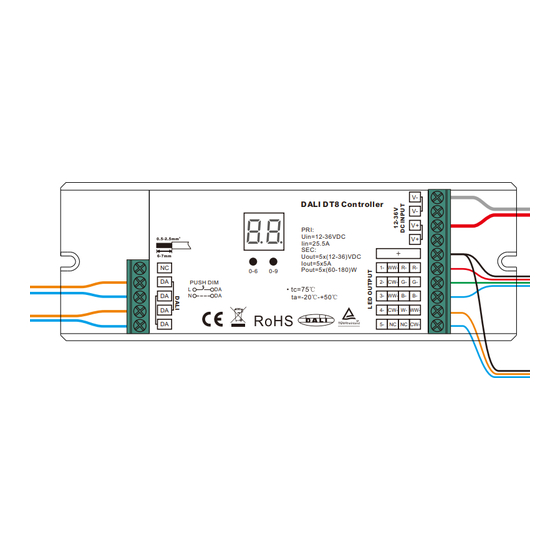
DALI-2 DT8 LED Controller
DI-DALI2-REC-5W
Important: Read All Instructions Prior to Installation
Digital display
DALI DT8 Controller
Input:
Uin=12-36VDC
Iin=25.5A
Output:
Uout=5x(12-36)VDC
Iout=5x5A
NC
Pout=5x(60-180)W
0-6
0-9
DA
PUSH DIM
L
DA
DA
N
DA
ta=-20℃-+50℃
DA
DA
2 groups DALI/Push
Manual set buttons
signal input & output
Product Data
Input
Output
Output
No.
Remarks
Voltage
Current
Power
5x5A
Constant voltage
1
12-36VDC
5x(60-180)W
2
5x350mA
Constant current
12-36VDC
5x(4.2-12.6)W
• In compliance with IEC 62386-101:2014, IEC 62386-102:2014, IEC 62386-207 Ed2, IEC 62386-209:2011
• Built-in DALI-2 interface, DALI DT8 device
• Multi-addresses enabled DT8 control gear
• Multi-devices integrated in one control gear
• Multi-functional, 8 in 1: Tc, RGBWAF, XY, 2*Tc, XY+Tc, RGB+Tc, XY+W (DT6), DT6
• DALI address manually assignable through manual set buttons and showed on the display
• Can be set as different device types: single-address types or multi-addresses types
• Single-address device types: Tc, RGBWAF, XY, DT6
• Multi-addresses device types: 2*Tc, XY+Tc, RGB+Tc, XY+W (DT6)
• 5 Channels constant voltage output
• Control of five PWM outputs via DALI device type 8
• Color control as defined in the DALI specification device type 8
• Supports DT8 device commands, compatible with universal DALI masters that support DT8 commands
• Configuration via DALI master USB interface
• Color temperature and RGB color control through push dim mode even if without DALI
• Waterproof grade: IP20
Safety & Warnings
• DO NOT install with power applied to device.
• DO NOT expose the device to moisture.
Operation
1. Select a DALI Device Type
1.1. Press and hold down both buttons until digital display flashes, then release the button.
1.2. Keep clicking the 2nd button, you will get the 8 device types one by one as follows:
V-
V-
DC power input
V+
V+
Common Anode Output(+)
CH 1:1/WW/R/R output(-)
1-
WW-
R-
R-
CH 2:2/CW/G/G output(-)
2-
CW-
G-
G-
CH 3:3/WW/B/B output(-)
3-
WW-
B-
B-
CH 4:4/CW/W/WW output(-)
4-
CW-
W-
WW-
CH 5:5/NC/NC/CW output(-)
5-
NC
NC
CW-
NC=No Connection
DALI
Dimming
Ambient
Size(LxWxH)
Consumption
Range
Temperature
170x59x29mm
-20℃ ~ +50℃
2mA
0.1%-100%
170x59x29mm
-20℃ ~ +50℃
2mA
0.1%-100%
,
means 2 Tc color type devices integrated in one control gear, which can control 2 groups of tunable white LED
separately using 2 DALI addresses under this mode.
,
means XY & Tc color type devices integrated in one control gear, which can control RGB & CCT LED separately
using 2 DALI addresses under this mode.
,
means RGBWAF & Tc color type devices integrated in one control gear, which can control RGB & CCT LED
separately using 2 DALI addresses under this mode.
,
means XY & DT6 type devices integrated in one control gear, which can control RGB & W LED separately using 2
DALI addresses under this mode.
, means XY coordinate color type, which can control RGB LED using 1 DALI address under this mode.
, means Tc color type, which can control tunable white LED using 1 DALI address under this mode.
, means RGBWAF color type, the device can control RGB+CCT LED using 1 DALI address under this mode.
, means DT6 device type, which can control single color LED using 1 DALI address under this mode.
1.3. Select a device type you would like and then press and hold down both buttons until digital display stops
flashing to confirm the selection.
2. Setting DALI address
2.1. Press and hold down the first button on the left until digital display flashes, then release the button.
2.2. Click any of the two buttons once to select a digit, click again to change the digit until the desired DALI
address appears. Click first button to set "tens" position and second button to set "units" position. The address
can be set from 00~63.
2.3. Then press and hold down any of the 2 buttons until the numeric digital display stops flashing to confirm the
setting.
Note: DALI address can be manually assigned from 00-63-FF, by factory defaults, no DALI address is
assigned for the dimmer, and the display shows
to factory defaults.
3. Once an address is selected, depending on the device type selected, the control gear may occupies 2
consecutive addresses or 1 address. For example, if the control gear is addressed to 22 on the display,
when the device type is multi-addresses type, the control gear occupies address 22 & 23, when the device
type is single-address type, the control gear occupies address 22.
4. DALI Address Assigned by DALI Masters
DALI address can also be assigned by DALI Master controller automatically, please refer to user manuals of
compatible DALI Masters for specific operations.
Note: The digital display will show
When the DALI master is assigning addresses. When the device
type is multi-addresses type, the control gear will be discovered as 2 separate devices.
5. Push Dimmer Mode
While connected with an AC push switch, the digital display will show "PD" which means Push Dimmer Mode,
operations under Push Dimmer Mode are as follows:
While
device type is selected, only the 1st group tunable white LED will be controlled by the push switch,
Click the button to switch ON/OFF
Ÿ
Press and hold down the button to increase or decrease light intensity to desired level and release it, then
Ÿ
repeat the operation to adjust light intensity to opposite direction. The dimming range is from 1% to 100%.
Double click the button to switch between brightness mode and color temperature mode.
Ÿ
Ÿ
Press and hold down the button to change color temperature under color temperature mode.
. Setting DALI address as
will reset the dimmer
Advertisement

Related Manuals for DIODE LED DI-DALI2-REC-5W


Summary of Contents for DIODE LED DI-DALI2-REC-5W
- Page 1 XY & Tc color type devices integrated in one control gear, which can control RGB & CCT LED separately using 2 DALI addresses under this mode. DI-DALI2-REC-5W means RGBWAF & Tc color type devices integrated in one control gear, which can control RGB & CCT LED separately using 2 DALI addresses under this mode.
- Page 2 While device type is selected, only the RGB LED will be controlled by the push switch, 1.2 When multi-addresses XY+Tc device type selected Ÿ Click the button to switch ON/OFF Press and hold down the button to increase or decrease light intensity to desired level and release it, then Ÿ...
- Page 3 1.4 When multi-addresses XY+Single Color(DT6) device type selected 1.6 When single-address Tc device type selected 12V/24V/36V CV PSU 12V/24V/36V CV PSU DALI DT8 Controller PRI: Uin=12-36VDC DALI DT8 Controller Iin=25.5A SEC: Uout=5x(12-36)VDC RGBW LED Strip Iout=5x5A PRI: Pout=5x(60-180)W Uin=12-36VDC PUSH DIM Iin=25.5A DALI Master SEC:...
- Page 4 2.2 When multi-addresses XY+Tc device type selected 1.8 When single-address DT6 device type selected 12V/24V/36V 12V/24V/36V CV PSU CV PSU AC PUSH SWITCH DALI DT8 Controller DALI DT8 Controller PRI: Uin=12-36VDC PRI: Iin=25.5A Uin=12-36VDC SEC: Connect with Single Color LED Strip Iin=25.5A Uout=5x(12-36)VDC Connect with RGB LED Strip...
- Page 5 2.5 When single-address XY device type selected 2.8 When single-address DT6 device type selected 12V/24V/36V CV PSU 12V/24V/36V CV PSU AC PUSH SWITCH DALI DT8 Controller AC PUSH SWITCH PRI: Uin=12-36VDC Connect with Single Color LED Strip Iin=25.5A SEC: DALI DT8 Controller Uout=5x(12-36)VDC Iout=5x5A Pout=5x(60-180)W...
- Page 6 1.3 When multi-addresses RGB+Tc device type selected 1.6 When single-address Tc device type selected 12V/24V/36V 12V/24V/36V CV PSU CV PSU DALI DT8 Controller DALI DT8 Controller PRI: Uin=12-36VDC PRI: Iin=25.5A Uin=12-36VDC SEC: Iin=25.5A Connect with RGB LED Strip 1st Group CCT LED Strip Uout=5x(12-36)VDC SEC: Iout=5x5A...
- Page 7 2. With Push Switch 2.4 When multi-addresses XY+Single Color(DT6) device type selected 12V/24V/36V 2.1 When multi-addresses Tc device type selected CV PSU 12V/24V/36V AC PUSH CV PSU SWITCH DALI DT8 Controller PRI: Uin=12-36VDC Iin=25.5A SEC: Uout=5x(12-36)VDC RGBW LED Strip Iout=5x5A Pout=5x(60-180)W AC PUSH PUSH DIM...
- Page 8 Conformity & Standards 2.7 When single-address RGBWAF device type selected • Radio Frequency Interference according to EN 55015:2013/A1:2015 • Immunity standard according to EN 61547:2009 • TÜV SÜD marked, CE marked 12V/24V/36V CV PSU AC PUSH SWITCH DALI DT8 Controller PRI: Uin=12-36VDC Iin=25.5A...
Need help?
Do you have a question about the DI-DALI2-REC-5W and is the answer not in the manual?
Questions and answers