Advertisement
Quick Links
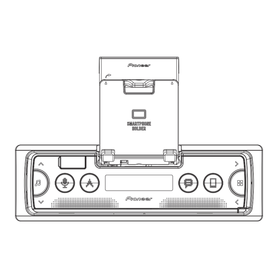
SMARTPHONE RECEIVER
SPH-10BT
SPH-C19BT
SPH-C10BT
PARKING SENSOR
ND-PS1
PIONEER CORPORATION
PIONEER ELECTRONICS (USA) INC. P.O. Box 1760, Long Beach, CA 90801-1760, U.S.A.
PIONEER EUROPE NV Haven 1087, Keetberglaan 1, 9120 Melsele, Belgium
PIONEER ELECTRONICS ASIACENTRE PTE. LTD. 2 Jalan Kilang Barat, #07-01, Singapore 159346
PIONEER CORPORATION 2018
/XEEL5
28-8, Honkomagome 2-chome, Bunkyo-ku, Tokyo 113-0021, Japan
SPH-10BT/XNEW5
/XNID
/XNES
ORDER NO.
CRT6293
/XNEW5
K-ZZZ AUG. 2018
Advertisement

Related Manuals for Pioneer SPH-10BT/XNEW5


Summary of Contents for Pioneer SPH-10BT/XNEW5
- Page 1 PIONEER CORPORATION 28-8, Honkomagome 2-chome, Bunkyo-ku, Tokyo 113-0021, Japan PIONEER ELECTRONICS (USA) INC. P.O. Box 1760, Long Beach, CA 90801-1760, U.S.A. PIONEER EUROPE NV Haven 1087, Keetberglaan 1, 9120 Melsele, Belgium PIONEER ELECTRONICS ASIACENTRE PTE. LTD. 2 Jalan Kilang Barat, #07-01, Singapore 159346 PIONEER CORPORATION 2018 K-ZZZ AUG.
- Page 2 CAUTION Danger of explosion if battery is incorrectly replaced. Replaced only with the same or equivalent type recommended by the manufacturer. Discard used batteries according to the manufacturer's instructions. SPH-10BT/XNEW5...
- Page 3 10.11 TUNER AMP UNIT (POWER AMP IC) ........................39 10.12 TUNER AMP UNIT (MIC AMP)(Not used)........................ 40 10.13 KEYBOARD UNIT ..............................41 11. PCB CONNECTION DIAGRAM ............................42 11.1 TUNER AMP UNIT ..............................42 11.2 KEYBOARD UNIT ..............................44 12. ELECTRICAL PARTS LIST ............................... 45 SPH-10BT/XNEW5...
- Page 4 Please be sure to conduct line process to original status if you make assembling after repair. 1.3 NOTES ON OPERATION CHECK / DIAGNOSIS Resetting the microprocessor 1. Remove the front panel. 2. Press the RESET button with a pointed instrument longer than 8 mm. RESET button SPH-10BT/XNEW5...
- Page 5 Be sure to use lead-free solder and a soldering iron that can meet specifications for use with lead-free solders for repairs accompanied by reworking of soldering. % To secure the front panel The front panel can be secured with the supplied screw. Screw XXX7020 SPH-10BT/XNEW5...
- Page 6 ! The Bluetooth ® word mark and logos are registered trademarks owned by the Bluetooth SIG, Inc. and any use of such marks by PIONEER CORPORATION is under license. Other trademarks and trade names are those of their respective owners. SPH-10BT/XNEW5...
- Page 7 See the table below for the items to be checked regarding audio: Item to be checked regarding audio Distortion Noise Volume too low Volume too high Volume fluctuating Sound interrupted 3.2 JIGS LIST - Grease List Name Grease No. Remarks Grease GEM1024 Attachment Assy Grease GEM1043 Attachment Assy SPH-10BT/XNEW5...
- Page 8 4. BLOCK DIAGRAM A SPH-10BT/XINUC BT MIC B SPH-C19BT/XNID FM/AM ANT Power Connector C SPH-C10BT/XNES PARKING WIRED REMOTE JA1276 SENSOR & FL FR JA1241 JA851 JA1232 JA101 TUNER AMP UNIT B.Up B.REM Power IC STBY IC1301 H-SW SYS8.5V TCB501HQ MUTE VDDIO_ON_SW VDDIO_ON3.3V MUTE...
- Page 9 1 000.0 mA Front USB USB1 REG4 (min 1500 mA) VD6.0V TUN3.3V TUN 3.3V Si-Tuner 215.0 mA 150.0 mA TEF6686AHN REG3 Lithio Voltage 3.14 3.30 3.47 Current 215.0 mA (min 300 mA) BUP14.4V BUP14.4V 300 mA 185 mA Power Amp SPH-10BT/XNEW5...
- Page 10 SWVDD5V = 5.4 V SWVDD5V : IC201 Pin 22 SYS+B8.5V = 8.5 V SYS+B8.5V : IC201 Pin 7 Starts communication LCD driver Source ON AMPPW = 3.3 V AMPPW : Pin R19 Completes power-on operation. (After that, proceed to each source operation) SPH-10BT/XNEW5...
- Page 11 Once the iPhone’s main menu is track/file. Pioneer Smart Sync connection is not displayed, reconnect the iPhone and made. reset it. – Make a connection with Pioneer Smart Sync. USB device/iPhone ERROR-23 USB device was not formatted properly. READING – Format the USB device with FAT12, Sometimes there is a delay between the FAT16 or FAT32.
- Page 12 REAR OUTPUT 1 FL+ 9 PKB SENSE SUBWOOFER 2 FR+ 10 NC OUTPUT 11 ILL 3 FL- 12 SYSTEM REMOTE 4 FR- 5 RL+ 13 ACC 6 RR+ 14 REV SENSE 7 RL- 15 B.UP 16 GND 8 RR- SPH-10BT/XNEW5...
- Page 13 D206 R577 C711 C723 R690 R529 D210 R642 R557 C717 R711 C724 R558 R511 R585 R513 C205 S503 L504 R559 C504 R544 R568 R249 D202 R518 R562 C1318 C1317 R1309 R165 C1232 P1232 P1231 R762 R766 C777 C780 C776 SPH-10BT/XNEW5...
- Page 14 Hold down the APP/MENU button and the RIGHT button and turn BUP and ACC ON. RIGHT APP/MENU [Check item of the PCL] Check that the frequency of the [PCL] test point is 32.768 kHz ± 1.31 Hz. [Repair method] Replace X502. SIDE B TUNER AMP UNIT SPH-10BT/XNEW5...
- Page 15 Note : Each sensor is adjusted with the control box on the production line. So please exchange the control box and 4 sensors as a set and do NOT replace them separately. Error Display Display on the main unit ERROR Display on Pioneer ENGLISH ERROR Detail...
- Page 16 The screen gets still when entering this item. On (an initial value or On (state when setting value of default entering test mode) Switching to next display menu) by pressing “ APP/MENU ” + “ RIGHT ” keys together. SPH-10BT/XNEW5...
- Page 17 Display Transition Diagram S/W UPDATE Push APP/MENU key Push APP/MENU key Update file data FILE ERROR CHECK FILE Detection Detection Detection OK UPDATE Complete DO NOT Update file data Loading POWER OFF Push APP/MENU key UPDATE Error COMPLETED ERROR-RETRY Automatically RESTART SPH-10BT/XNEW5...
- Page 18 Slide the Tuner Amp Unit Section in the direction of the arrow and then remove the Tuner Amp Unit Section. Chassis Fig.2 Removing the Tuner Amp Unit (Fig.3) Tuner Amp Unit Remove the two screws and then remove the Tuner Amp Unit. Fig.3 SPH-10BT/XNEW5...
- Page 19 Disassembling the Panel Part (Fig.5, 6) 1. Remove the arm while bending the rib of the panel upward. Fig.5 2. Press the upside hook and the bottom side hook of the button at the same time, and pull out the button. Fig.6 SPH-10BT/XNEW5...
- Page 20 Fig.9 8. EACH SETTING AND ADJUSTMENT There is no information to be shown in this chapter. SPH-10BT/XNEW5...
- Page 21 Screw adjacent to mark on the product are used for disassembly. For the applying amount of lubricants or glue, follow the instructions in this manual. (In the case of no amount instructions,apply as you think it appropriate.) 9.1 PACKING SECTION SPH-10BT/XNEW5 SPH-10BT/XNEW5 SPH-C19BT/XNID SPH-C10BT/XNES...
- Page 22 See Contrast table (2) Case Assy QXA3129 Warranty Card See Contrast table (2) MBL PWS Conn-Cord See Contrast table (2) (2) CONTRAST TABLE SPH-10BT/XNEW5, SPH-C19BT/XNID and SPH-C10BT/XNES are constructed the same except for the following: Mark Description SPH-10BT/XNEW5 SPH-C19BT/XNID SPH-C10BT/XNES Unit Box CHG9630...
- Page 23 9.2 EXTERIOR SECTION Refer to "9.3 ATTACHMENT ASSY SECTION". SPH-C19BT/XNID SPH-C10BT/XNES SPH-10BT/XNEW5 SPH-10BT/XNEW5...
- Page 24 CNW4004 Cover CNU4143 Spring CBH2210 Screw BPZ20P100FTC Tuner Amp Unit See Contrast table (2) (2) CONTRAST TABLE SPH-10BT/XNEW5, SPH-C19BT/XNID and SPH-C10BT/XNES are constructed the same except for the following: Mark Description SPH-10BT/XNEW5 SPH-C19BT/XNID SPH-C10BT/XNES Grille Assy CXF1939 CXF1942 CXF1940 Keyboard Unit...
- Page 25 9.3 ATTACHMENT ASSY SECTION • Bottom view SPH-10BT/XNEW5...
- Page 26 • • • • • • • • • • • • • • • CNW3990 Spring CBH3159 Frame Unit CXF1766 • • • • • • • • • • Cover CNU4129 Cover CND7994 Holder CNW3991 Holder CNW3992 Holder CNW3993 Holder CNW3994 SPH-10BT/XNEW5...
- Page 27 Inside part of the Rail (1) : GEM1024 (2) : GEM1043 SPH-10BT/XNEW5...
- Page 28 PACKING SECTION (ND-PS1/XEEL5) PARTS LIST Mark No. Description Part No. Mark No. Description Part No. Fastener 144.00579A Cord Assy 081.04115A Installation Manual CRB5177 Cord Assy 081.04116A Installation Manual Part No. Language CRB5177 English, French, Spanish(Espanol), Italian, Dutch, Portuguese(B), Spanish(Mexican), German, Russian, Persian, Arabic SPH-10BT/XNEW5...
- Page 29 NOTE : 1/12 10. SCHEMATIC DIAGRAM TUNER AMP UNIT Symbol indicates a resistor. (S_VEHICLE IF) Note: When ordering service parts, be sure to refer to " EXPLODED VIEWS AND PARTS LIST" or No differentiation is made between chip resistors and "ELECTRICAL PARTS LIST".
- Page 30 2/12 TUNER AMP UNIT (PWR_SYS_REG) VD6V L202 Q202 VDDIO3.3V VDDIO_ON3.3V SSM3J332R C261 R210 Q205 0.1u/10 SSM3J332R RRR040P03 C207 0.1u/10 R212 FET-P Q203 IC201 R263 R201 GATE1 USB1_5V C248 R223 SNSL INV1 1u/50 0.02 1608 SNSH VOUT4 C233 C220 VIN2 ADJ4 D208 10u/35 RB751SM-40...
- Page 31 3/12 TUNER AMP UNIT (OTHER SUPPLY) ILM+B HIOUTCLK H I O U T C L K 4/12 ILMPW BT_ON B T _ O N HIOUT17V * D 4 6 1 * L 4 6 1 RGB Supply 17.1V * R 3 0 1 1608 *IC461 G N D...
- Page 32 4/12 TUNER AMP UNIT (SYSCOM) VDD1.2 1/12 PBSENS R 5 3 2 P B S E N S BGSENS B G S E N S 2 . 2 k BSENS2 B S E N S 2 ASENS R 5 6 5 A S E N S 1/12 1/12...
- Page 33 5/12 TUNER AMP UNIT (I/F iPod FLASH MEM) VDDIO3.3V VDDIO3.3V CPPWR C P P W R CP_SCL C P _ S C L CP_SDA C P _ S D A FLASH MEMORY IC743 CP_RST C P _ R S T H O L D 1 ROMCS R O M C S...
- Page 34 6/12 TUNER AMP UNIT (E-VOL) I N F L I N F R I N R L I N R R I N S W L I N S W R 4/12 I G O U T L I G O U T R E V O L _ S C L E V O L _ S D A B E E P...
- Page 35 7/12 TUNER AMP UNIT (LITHIO) TUN3.3V T u n e r _ L 6/12 T u n e r _ A G L 8 5 5 L 8 5 2 CTF1786- T u n e r _ R R 8 8 9 X 2 3 G N D 2 R 8 7 0...
- Page 36 8/12 TUNER AMP UNIT (BT) BTGND BT3.3V C 1 0 0 5 HOTWAKE BT_CTS C L K _ R E Q H O S T W A K E U A R T _ C T S N C 1 BT_3.3V BT_RTS U A R T _ R T S...
- Page 37 9/12 TUNER AMP UNIT (S11.6 I/F)(Not used) VDDIO3.3V VDDIO_ON3.3V VD6V MECHA VD * R 1 1 1 5 * C N 1 1 0 1 * R 1 1 2 8 * R 1 1 1 6 * R 1 1 1 7 * R 1 1 1 9 * R 1 1 0 5 CDSRQ...
- Page 38 10/12 TUNER AMP UNIT (EXT I/F) WIRED REMOTE/BT MIC PARKING JA1276 SENSOR CKN1103-A CONNECTOR BUP14.4V 11/12 RCAMUTE R C A M U T E P 1 2 7 6 * J A 1 2 3 2 F S M D 0 7 5 - 2 4 R C K S 6 6 0 3 BT_MICN * P 1 2 3 2...
- Page 39 11/12 TUNER AMP UNIT (PWR AMP IC) C 1 3 1 6 0.1u 50V 1608 **TAB1&P-GND2 * R 1 3 0 9 R 1 3 0 6 * I C 1 3 0 1 A M P P W **TAB1&GND 1 0 k * R 1 3 1 1 4/12...
- Page 40 12/12 TUNER AMP UNIT (MIC AMP) (Not used) MIC SELECTOR MIC AMP KARAOKE MODEL * L 1 4 0 1 KARAOKE MODEL * Q 1 4 0 2 4/12 S E L M I C * R 1 4 2 8 *Q1401 E 2 4 G N D...
- Page 41 KEYBOARD UNIT GRILLE uCOM KEY MATRIX LCDTOSYS SYSTOLCD S 1 8 2 1 S 1 8 2 4 S 1 8 2 8 CN1881 CKS6287- SOURCE CSG1155- CSG1155- CSG1155- SEG16 R_LEFT DGND LEFT RIGHT APP/MENU SEG17 G_LEFT ILMGND S 2 3 L 1 8 8 1 DGND SEG18...
- Page 42 11.PCB CONNECTION DIAGRAM PARKING SENSOR CONNECTOR FM/AM TUNER AMP UNIT SIDE A WIRED REMOTE ANTENNA REAR/FRONT JA1232 /BT MIC /SUBWOOFER OUTPUT NOTE FOR PCB DIAGRAMS JA1276 JA1231 POWER SUPPLY JA1241 1.The parts mounted on this PCB L101 JA101 include all necessary parts for IC1301 several destination.
- Page 43 TUNER AMP UNIT SIDE B C1318 C1317 R1310 R1309 R165 C1232 P1232 C1255 P1231 Q1302 R1313 C1321 R762 R766 C777 C780 C776 R770 C790 C885 IC761 L1231 C778 R765 C761 R768 C762 R767 R530 L514 C721 C528 C527 R613 C879 C719 R611 C594...
- Page 44 SIDE A KEYBOARD UNIT S1823 S1828 VOL UP JA1861 RIGHT S1822 S1825 S1826 S1829 V1801 MAIL PHONE S1827 NAVI S1824 D1903 D1901 D1902 APP/MENU SOUCE LEFT S1821 S1830 IC1851 D1904 D1905 VOL DOWN KEYBOARD UNIT SIDE B CN1201 C1851 R1853 Q1909 R1852 C1924...
- Page 45 The expression of the unit in this manual is shown by u instead of . Please do not make a mistake. Circuit Symbol and No. Part No. Circuit Symbol and No. Part No. Q 202 SSM3J332R A:SPH-10BT/XNEW5 Q 203 Power MOS FET RRR040P03 B:SPH-C19BT/XNID Q 204 Resistor Built-in Transistor...
- Page 46 R 441 XRS1/16SS103J R 142 XRS1/16SS473J R 442 XRS1/10SR221J R 143 XRS1/16SS103J R 503 XRS1/16SS3R3J R 144 XRS1/16SS472J R 504 XRS1/16SS3R3J R 145 XRS1/16SS0R0J R 505 XRS1/16SS221J R 151 XRS1/16SS102J R 506 XRS1/16SS473J R 152 XRS1/16SS223J R 507 XRS1/16SS473J SPH-10BT/XNEW5...
- Page 47 R 659 XRS1/16SS101J R 573 XRS1/16SS473J R 660 XRS1/16SS101J R 574 XRS1/16SS473J R 661 XRS1/16SS101J R 663 XRS1/16SS101J R 575 XRS1/16SS473J R 576 XRS1/16SS473J R 664 XRS1/16SS101J R 577 XRS1/16SS0R0J R 672 XRS1/16SS101J R 578 XRS1/16SS473J R 701 XRS1/16SS103J SPH-10BT/XNEW5...
- Page 48 R 863 XRS1/16SS103J R 868 XRS1/16SS103J R 1307 XRS1/16SS0R0J R 870 XRS1/16SS101J R 1308 RS1/8SQ0R0J R 871 XRS1/16SS0R0J R 1312 XRS1/16SS103J R 872 XRS1/16SS0R0J R 1313 XRS1/16SS102J R 1321 XRS1/16SS0R0J R 873 XRS1/16SS182J R 874 XRS1/16SS101J R 1322 XRS1/16SS0R0J SPH-10BT/XNEW5...
- Page 49 C 239 CCSSCH100D50 C 538 CKSRYX106M6R3 C 240 CCSSCH100D50 C 539 CKSSYB103K16 C 241 CKSQYX106K10 C 540 CKSRYX106M6R3 C 242 CKSSYB104K16 C 541 CKSSYB222K50 C 243 CKSYX106K35 C 542 CKSSYB104K10 C 244 CKSSYB102K50 C 543 CKSSYX105K10 C 245 CKSYX106K35 SPH-10BT/XNEW5...
- Page 50 C 785 CKSRYX105K16 C 787 CKSQYX106K16 C 1304 CKSQYB474K25 C 788 CKSQYX106K16 C 1305 CKSSYB104K10 C 790 CKSRYX106M6R3 C 1306 CKSRYB474K10 C 791 CKSSYB103K25 C 1308 CKSRYX104K50 C 1310 CKSQYX106K16 C 794 CCSSCH101J50 C 853 CCSSCH120J50 C 1311 CKSRYX225K10 SPH-10BT/XNEW5...
- Page 51 R 1853 (B,C) RS1/16SS101J R 1881 RS1/10SR222J R 1882 RS1/10SR222J R 1883 RS1/10SR222J R 1884 RS1/10SR222J R 1901 RS1/10SR152J R 1902 RS1/10SR680J R 1903 RS1/16SS332J R 1904 RS1/10SR152J R 1905 RS1/10SR680J R 1906 RS1/16SS332J R 1907 RS1/10SR152J R 1908 RS1/10SR680J SPH-10BT/XNEW5...
Need help?
Do you have a question about the SPH-10BT/XNEW5 and is the answer not in the manual?
Questions and answers