Advertisement
Quick Links
Multifunction Meters
Transducers & Isolators
Temperature Controllers
Converters & Recorders
Digital Panel Meters
Current Transformers
Analogue Panel Meters
Shunts
Digital Multimeters
Clamp Meters
Insulation Testers
This manual superseded all previous versions – please keep for future reference
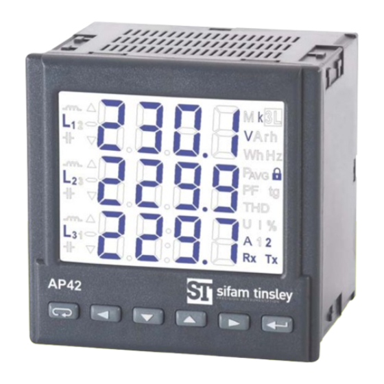
AP42
NETWORK PARAMETER METER
User Manual - Issue 1.0
SUBJECT TO CHANGE WITHOUT NOTICE
MULTIFUNCTION METER
AP42
www.sifamtinsley.co.uk
Advertisement

Related Manuals for Sifam Tinsley AP42


Summary of Contents for Sifam Tinsley AP42
- Page 1 MULTIFUNCTION METER AP42 www.sifamtinsley.co.uk Multifunction Meters Transducers & Isolators Temperature Controllers Converters & Recorders AP42 Digital Panel Meters NETWORK PARAMETER METER Current Transformers Analogue Panel Meters User Manual - Issue 1.0 Shunts Digital Multimeters Clamp Meters Insulation Testers SUBJECT TO CHANGE WITHOUT NOTICE...
- Page 2 12. MAINTENANCE AND GUARANTEE...................21 1. Application The AP42 meter is a digital programmable panel meter destined for the measurement of the 3-phase, 4-wire power network parameters in balanced and unbalanced systems. It is also capable of displaying measured quantities and their simultaneous digital transmission. The meter is also capable of controlling and optimization of the power electronic devices, systems, and industrial installations.
- Page 3 4. Installation AP42 Meter is adapted to be mounted to the panel with mounting brackets (see Fig. 1). Meter housing is made of plastic. Housing dimensions: 96 x 96 x 77 mm. On the outer side of the meter there are screw and tab terminal strips that can be used for connecting external wires with diameter up to 2.5 mm...
- Page 4 AP42 METER OF NETWORK PARAMETERS Fig. 2. Meter dimensions. 5. Meter Description 5.1. Current inputs All current inputs are galvanically isolated (internal current transformers). The meter is suited to operate together with external measuring current transformers. Displayed values of currents as well as their derivative values are automatically calculated using set ratio value of the external transformer.
- Page 5 3 current transformers and 3 voltage transformers in 4-wire network Caution: It is recommended to connect AP42 meters (RS- 485) to a computer with a shielded wire. A shield should be connected to ground in a single point. Shielded wire must be used in case there are many interferences in the environment.
- Page 6 AP42 METER OF NETWORK PARAMETERS 6.2 Power-on Messages After connection of voltage inputs the meter performs a display test and displays the AP42 meter name, build and current software version. where: r n.nn is a number of the current software version or special build number. b n.nn is a bootloader version number.
- Page 7 When alarms are activated, symbols A1 and/or A2 are displayed. When alarms are deactivated and alarm signalization latch is turned on, flashing symbols A1 and/or A2 are displayed. 6.4 Operating Modes Fig. 6. AP42 meter operating modes. MULTIFUNCTION METER Issue 1.0...
- Page 8 AP42 METER OF NETWORK PARAMETERS 6.5 Parameter Setting AP42 meters are configured with the use of LPCon software available for free on the www.sifamtinsley.co.uk web site. Fig 7. Setup menu. Programming mode is enabled by pressing and holding button for about 3 seconds. To enable the programming user bust enter a correct access code.
- Page 9 AP42 METER OF NETWORK PARAMETERS 6.5.2 Setting of Output Parameters In Options choose the out mode and confirm your choice by pressing the button. Table 4 The write of the value ALon lower than ALoF switches the alarm off. Selection of the monitored value: Table 6 6.5.3 Setting alarm parameters...
- Page 10 AP42 METER OF NETWORK PARAMETERS *Un, In – voltage and current rated values MULTIFUNCTION METER Issue 1.0...
- Page 11 AP42 METER OF NETWORK PARAMETERS a) n-on b) n-oFF c) On d) OFF Fig. 8. Alarm types (x – alarm no.): a),b) normal c) off d) on. MULTIFUNCTION METER Issue 1.0...
- Page 12 2500: 5A, voltage 230 V. Peak max power consumption 1,5 MW. Calculations: AP42 meter active rated 3-phase power: P = 3 x k u x U n x k I x I n = 3 x 1 x 230 V x 500 x 5A = 1,725 MW g100 %.
- Page 13 AP42 METER OF NETWORK PARAMETERS Set alarm as following: monitored quantity: A1_n = P_ord; alarm type: A1_t = n-on; A1on = 90,0, AL1oF = 89,9; delay time A1dt = 0 or 60 s; A1_s = 0; A1_b = 0. Parameters should be set as following: tr_I = 500; Syn = 15 or c_15, and Pord = 57.9.
- Page 14 7. Software Upgrade AP42 meter (with digital output) allows for firmware upgrade via PC with LPCon software installed. LPCon software is available as freeware on the www.sifamtinsley.co.uk web site. Upgrade is possible if PC is connected to RS485 to USB converter, such as PD10 converter.
- Page 15 AP42 meter register map AP42 meter has data contained in 16-bit and 32-bit registers. Process variables and meter parameters are placed in the address area of registers in a way depended on the variable value type. Bits in 16-bit registers are numbered from the youngest to the oldest (b0-b15). 32-bit registers include numbers of float type in IEEE-754 standard.
- Page 16 AP42 METER OF NETWORK PARAMETERS MULTIFUNCTION METER Issue 1.0...
- Page 17 AP42 METER OF NETWORK PARAMETERS Bit 7 – „1” – reactive capacitive energy display Brackets [ ] contain, respectively: resolution or unit. Bit 6 – „1” – active exported energy display Energy is made available in hundreds of watt-hours (var-hours) in double 16-bit register, and for this reason, one must divide them by 10 when Bit 5 –...
- Page 18 AP42 METER OF NETWORK PARAMETERS MULTIFUNCTION METER Issue 1.0...
- Page 19 AP42 METER OF NETWORK PARAMETERS When lower limit is exceeded, a -1e20 value is displayed. Conversely, when upper limit is exceeded, a 1e20 value is displayed. MULTIFUNCTION METER Issue 1.0...
- Page 20 AP42 METER OF NETWORK PARAMETERS 10. Technical Data 9. Error Codes Measuring Ranges and Admissible Basic Errors During the meter operation, error messages may be displayed. Following list shows causes of particular errors.- Table 11 Err1 – too low voltage or current during measurement: - PF , tgφ...
- Page 21 AP42 METER OF NETWORK PARAMETERS Power consumption: AP42 meter complies with following standards: - in L1 and L2 voltage circuit ≤0.05 VA Electromagnetic compatibility: - in L3 voltage circuit ≤3 VA - interference immunity acc. to EN 61000-6-2 - in current circuits ≤0.05 VA...
- Page 22 AP42 METER OF NETWORK PARAMETERS 12. Maintenance and Guarantee 11. Ordering Codes Table 12 The AP42 does not require any periodical maintenance. In case of some incorrect operations: AP42 - After the dispatch date and in the period stated in the guarantee...
- Page 23 AP42 METER OF NETWORK PARAMETERS Contact Sifam Tinsley Instrumentation Ltd 1 Warner Drive Tel: 01376 335271 Springwood Industrial Estate E-mail: sales@sifamtinsley.com Braintree, Essex CM7 2YW www.sifamtinsley.co.uk MULTIFUNCTION METER Issue 1.0...
Need help?
Do you have a question about the AP42 and is the answer not in the manual?
Questions and answers