Advertisement
Quick Links
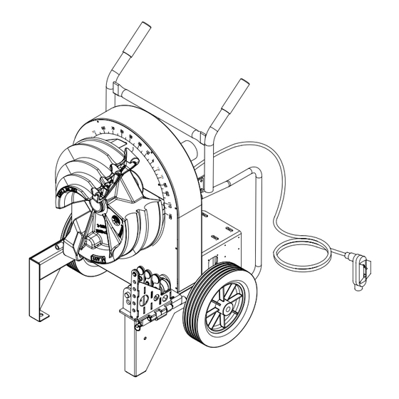
Current Tools™ 77 Series Electric Bender
with Single Shoe Groups
for bending 1/2" thru 2" RIGID - EMT - IMC
PVC Coated Rigid and Aluminum EMT conduit
Operating, Maintenance, Safety
This manual is free of charge. All personnel who operate this Bender should have a copy of this manual and read and
understand its contents. To request a copy, call or write to the address below. All information, specifications and
product designs may change due to design improvements or updates and are subject to change without notice.
Current Tools does not assume any liability for damages resulting from misuse or incorrect application of its products.
CURRENT TOOLS • P . O. BOX 17026 GREENVILLE, SC 29606
800.230.5421 or 864.721.4230 • FAX 864.721.4232
and Parts Manual
Read and understand this material before
operating or servicing this Bender. Failure to
understand how to safely operate and service
this unit may result in serious injury or death.
www.currenttools.com
U L
®
LISTED
CONDUIT BENDER
C U L
®
01/24
Advertisement

Related Manuals for Current Tools 77 Series


Summary of Contents for Current Tools 77 Series
- Page 1 Current Tools does not assume any liability for damages resulting from misuse or incorrect application of its products. CURRENT TOOLS • P . O. BOX 17026 GREENVILLE, SC 29606 800.230.5421 or 864.721.4230 •...
- Page 2 TABLE OF CONTENTS Safety Alerts ..................3 Important Safety Information ............4, 5 Specifications – 77 Series Electric Bender ........6 Model Descriptions ................ 6 Features ..................6, 7 Shoe Groups ................... 8 Conduit Centerline Bending Radii ..........8 Grounding Instructions ..............9 Mounting Roller Support ..............
- Page 3 SAFETY ALERTS Safety Alert Symbol THIS SAFETY SYMBOL is used to call your attention to instructions that concern your personal safety. It means: ATTENTION! BE AWARE! THIS IS AN IMPORTANT SAFETY INSTRUCTION! Read, understand, and follow these safety instructions. Failure to follow these safety instructions may result in injury or death.
- Page 4 RETAIN SAFETY INFORMATION This manual should be read and understood by all personnel who operate or service this bender. Failure to understand how to safely operate and service this unit could result in injury or death. This unit should only be operated and serviced by qualified personnel.
- Page 5 DANGER IMPORTANT SAFETY INFORMATION continued — WARNING ALWAYS use recommended accessories. Consult this manual for DANGER recommended accessories. The use of improper accessories may cause risk of injury. CAUTION DANGER WARNING ALWAYS keep hands and feet away from pinch points such as bending shoes, roller supports and conduit when bender is in use.
- Page 6 1/2" thru 2" schedule 40 steel pipe install or remove these 1/2" thru 2" aluminum EMT shoes and roller supports. The 77 Series Electric Bender is NOT to be used for bending any conduit or pipe wall thickness above schedule 40 pipe. width 29 1/2"...
- Page 7 When replacing handle, be sure to replace screws and nuts and also to tighten securely before moving or transporting. The 77 Series Electric Benders may also be used in a horizontal position The bender can operate in this position as efficiently as it does in the upright position.
- Page 8 SINGLE SHOE GROUPS RIGID 700SR - for bending 1/2" thru 2" RIGID conduit, 1/2" thru 700SI - for bending 1/2" thru 2" IMC conduit 1 1/4" IMC conduit and 1/2" thru 2" schedule 40 pipe includes the following items. includes the following items. Catalog# Description Catalog# Description 2-3000...
- Page 9 GROUNDING INSTRUCTIONS WARNING ELECTRIC SHOCK HAZARD! Only connect the bender to a 20 AMP GFCI protected circuit. DO NOT modify the plug which is provided with the unit. Failure to follow these warnings can result in serious injury or death. RECEPTACLE PLUG Figure 9a...
- Page 10 Model #77 Bender. In addition, most bending shoes and attachments ® ® ® for the Model #77 Bender will fit the Greenlee and 555 Classic bender. Contact Current Tools for specific applications and compatibility. * Greenlee® 555® and 555 Classic® are registered trademarks of Greenlee/Textron.
- Page 11 MOUNTING BENDING SHOE Choose the correct bending shoe for the type conduit you will be bending (RIGID, IMC, EMT, PVC coated RIGID or aluminum EMT) and slide shoe onto the main drive sprocket shaft. See Figure 11a. Bending Shoe Sprocket Shaft Main Drive Drive Sprocket...
- Page 12 GENERAL BENDING INSTRUCTIONS Bending instructions for: 1/2" thru 2" RIGID conduit 1/2" thru 1 1/4" EMT conduit 1/2" thru 1 1/4" IMC conduit 1/2" thru 2" 40 mil PVC coated RIGID conduit 1/2" thru 2" schedule 40 pipe 1/2" thru 2" aluminum EMT See pages 10 and 11 for mounting shoe and roller support.
- Page 13 GENERAL BENDING INSTRUCTIONS continued — 3. After marking the pipe/conduit, place it into the bender. See Figure 12. The pipe/conduit should slide over the correct size roller support, through the shoe groove and into the hook. The bending mark should be at the front ( OUTSIDE ) edge of the hook.
- Page 14 BENDING INSTRUCTIONS FOR 1 1/2" AND 2" EMT & IMC CONDUIT 1. See pages 10 and 11 for mounting shoe and roller support. Be sure to match the appropriate shoe with its corresponding roller support. NOTE: The frame color of the EMT roller support is silver (see Figure 14a). The frame color of the IMC roller support is yellow (see Figure 14b).
- Page 15 BENDING INSTRUCTIONS FOR 1 1/2" AND 2" EMT & IMC CONDUIT continued — 3. Rotate the bending shoe to 10 degrees below the 0 (zero) degree setting. See Figure 12. 4. After marking the pipe/conduit, place it into the bender. The pipe/conduit should slide over the roller support and through the shoe groove and into the hook.
- Page 16 BENDING INSTRUCTIONS FOR 1 1/2" AND 2" EMT & IMC CONDUIT continued — 6. Keep foot pressure on the engaging pedal and push the “Bend/Unload” switch to the “Bend” position. Then press the “Jog” button. The conduit will pull the roller support against the stop. Foot pressure can then be removed from the engaging pedal.
- Page 17 SQUEEZE ADJUSTMENT PROCEDURE FOR 1 1/2" AND 2" EMT & IMC ROLLER SUPPORTS The 1 1/2" and 2" rollers on the single shoe EMT Roller Support and the 1 1/2" and 2" rollers on the single shoe IMC Roller Support on the 77 bender have a Squeeze Adjustment feature if wrinkling or side marking becomes a problem during the bending process.
- Page 18 BENDING INSTRUCTIONS FOR 1/2" TO 1" ALUMINUM EMT 1. Mount the correct roller support for 1/2" thru 1" aluminum EMT conduit (part #2-4400) according to the instructions on page 10. See Figure 18a 2. Install the bending shoe (part #2-3100) as shown on page 11. 3.
- Page 19 BENDING INSTRUCTIONS FOR 1 1/4" AND 2" ALUMINUM EMT 1. Mount the correct roller support for 1 1/4" thru 2" aluminum EMT (part #2-4500) according to the instructions on page 10. 2. Use the roller support engaging pedal to lift the rollers. Locate the pull pin on the inside of the rollers and pull the pin to release the 1 1/4"...
- Page 20 BENDING INSTRUCTIONS FOR 1 1/2" AND 2" ALUMINUM EMT 1. Mount the correct roller support for 1 1/4" thru 2" aluminum EMT (part #2-4500) according to the instructions on page 10. 2. Use the roller support engaging pedal to lift the rollers. Locate the pull pin on the inside of the rollers and pull the pin to release the 1 1/4"...
- Page 21 MAINTENANCE WARNING ALWAYS disconnect power supply before removing any guards or covers and before servicing this bender. Failure to do so may result in serious injury or death. 1. The Gear Box is filled with oil at the factory and should not require periodic flushing.
- Page 22 MAINTENANCE continued — 3. To inspect REAR #40 chain tension: • Check chain tension after an initial break-in period of 2 - 3 hours of use and tighten per the instructions below. See Figure 22. Thereafter, inspect monthly. • Remove the chain guard by taking out the 2 mounting screws. •...
- Page 23 STUB-UP BENDING INFORMATION AND CHARTS — continued To locate bending marks and springback of 15, 30, 45, 60, and 90 degree bends for a desired stub: 1. Check Chart A, B, C or C1 on Page 24 for deduct length. Note that minimum stub length is deduct length plus 2".
- Page 24 STUB-UP BENDING INFORMATION AND CHARTS — continued Chart A – RIGID Conduit/Schedule 40 Pipe Conduit Deduct ————— Springback ————— Size Length 15° 30° 45° 60° 90° 1/2" 7-1/2 3/4" 1" 1 1/4" 13-5/8 1 1/2" 14-7/8 2" 16-1/8 Chart B – EMT and Aluminum EMT Conduit Deduct —————...
- Page 25 OFFSET BENDING INFORMATION AND CHARTS To locate bending marks for a desired offset: 1. Measure distance from end of conduit to start of bend and mark conduit. ( Mark 1 ) See Figure 25a and 25b. 2. Refer to chart E for measurement “X" (see page 26) and deduct this distance from Mark 1 and place Mark 2 on conduit.
- Page 26 OFFSET BENDING INFORMATION AND CHARTS — continued To locate center-to-center distance of offset bending marks other than those listed in Chart D, use the following multipliers. Multiply the height of offset desired by 3.86 on 15 degree bends, 2 on 30 degree bends, and 1.4 on 45 degree bends.
- Page 27 TROUBLESHOOTING WARNING ALWAYS disconnect power supply before removing any guards or covers and before servicing this bender. Failure to do so may result in serious injury or death. Problem Cause Diagnosis Cure 1. Bender will not operate Power source Check for voltage If power is on, at power source go to ( #3 )
- Page 28 PARTS LIST refer to on pages 30 & 31 EXPLODED VIEWS...
- Page 29 EXPLODED VIEWS continued — 76(7),80 44 (7) ELECTRICAL PLATE MOUNTING HOLES-BENDER FRAME CIRCUIT BREAKER SWITCH REMOTE PENDANT...
- Page 30 PARTS LIST — 77 SERIES ELECTRIC BENDER ITEM # PART # DESCRIPTION 1 ... 77-375 ..1 ....FRAME 2 .
- Page 31 PARTS LIST continued — ITEM # PART # DESCRIPTION 41 ... 77-041 ..2 ... FITTING - 90° LIQUITITE 42 .
- Page 32 ELECTRICAL SYSTEM DIAGRAM...
- Page 33 PARTS LIST — SINGLE SHOES & ROLLER SUPPORTS 2-3000 & 2-4000 Bending Shoe & Roller Support — 1/2" to 2" RIGID Conduit AND Schedule 40 pipe 1/2" to 1 1/4" IMC conduit ITEM # PART # DESCRIPTION 1 ....2-1304 ....4 .............DRIVE STUD 2 ....
- Page 34 PARTS LIST — SINGLE SHOES & ROLLER SUPPORTS 2-3200 & 2-4300 Bending Shoe & Roller Support — 1/2" to 2" PVC Coated RIGID Conduit ITEM # PART # DESCRIPTION 1.......2-1304 ..... 4 ..........DRIVE STUD 2..... 2-2301-2 ....3 ...... SCREW, SHOULDER SOCKET — 3/4 × 1 1/2" 3.......2-3203 .....
- Page 35 PARTS LIST — SINGLE SHOES & ROLLER SUPPORTS 2-3100 Bending Shoe 1/2" to 2" EMT Conduit ITEM # PART # DESCRIPTION 1 ....2-1304 ......4 ........DRIVE STUD 2 ....2-2301-2 ...... 3 ..SCREW, SHOULDER SOCKET — 3/4" × 1 1/2" 3 ....
- Page 36 PARTS LIST — SINGLE SHOES & ROLLER SUPPORTS 2-4200 Roller Support 1/2" to 2" EMT Conduit ITEM # PART # QTY. DESCRIPTION 1 ....2-1103 ....2 .........ROLLER - 1.5" EMT 2 ....2-1108 ....1 ........SPACER TUBE 3 ....2-1109 ....4 ....... 3/4" RETAINER RING 4 ....2-1111 ....
- Page 37 PARTS LIST — SINGLE SHOES & ROLLER SUPPORTS 2-3000 Bending Shoe 1/2" to 2" IMC Conduit ITEM # PART # DESCRIPTION 1 ....2-1304 ......4 ........DRIVE STUD 2 ....2-2301-2 ...... 3 ..SCREW, SHOULDER SOCKET — 3/4" × 1 1/2" 3 ....
- Page 38 PARTS LIST — SINGLE SHOES & ROLLER SUPPORTS 2-4100 Roller Support — 1/2" to 2" IMC Conduit ITEM # PART # QTY. DESCRIPTION 1 ....2-1108 ......1 ........SPACER TUBE 2 ....2-1109 ......4 ........3/4" RETAINER RING 3 ....2-1111 ......1 ......187" DIA. X 1.25 LG ROLL PIN 4 ....
- Page 39 PARTS LIST — SINGLE SHOES & ROLLER SUPPORTS 2-4400 Roller Support — 1/2" to 1" Aluminum EMT Conduit ITEM # PART # QTY. DESCRIPTION 1 ....2-1109 ......4 ........3/4" RETAINER RING 2 ....2-1111 ......1 ......... PIN-ROLL 3/16" × 1.25" 3 ....
- Page 40 PARTS LIST — SINGLE SHOES & ROLLER SUPPORTS 2-4500 Roller Support — 1 1/4" to 2" Aluminum EMT Conduit ITEM # PART # QTY. DESCRIPTION 1 ....2-1109 ......4 ........3/4" RETAINER RING 2 ....2-1111 ......1 ......... PIN-ROLL 3/16" × 1.25" 3 ....
- Page 41 PARTS LIST — SINGLE SHOES & ROLLER SUPPORTS 2-4500-104 Roller Assembly for 1 1/4" 2-4500-104 Roller Assembly for 1 1/4" ITEM # PART # QTY. DESCRIPTION 1 ....2-1118 ......4 ..... SCREW - FLAT SOCKET (7/16-14 × 1) 2 ..... 2-4500-103 ......2 ........SIDE PLATE - 1-1/4 3 .....
- Page 42 PARTS LIST — SINGLE SHOES & ROLLER SUPPORTS 2-4500-104 Roller Assembly for 2" ITEM # PART # QTY. DESCRIPTION 1 ....2-1116 ......2 ........ROLLER - 2" EMT 2 ....2-1118 ......4 ..... SCREW - FLAT SOCKET (7/16-14 × 1) 3 .....
Need help?
Do you have a question about the 77 Series and is the answer not in the manual?
Questions and answers