Table of Contents
Advertisement
Quick Links
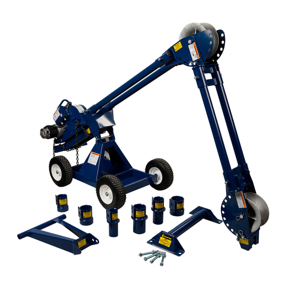
Current Tools™ 8885/8890 Series – The Mantis™
Mobile Cable Pulling Packages
Current Tools™ Model 8085 and Model 8090
Mobile Cable Pulling Carriage
Operating, Maintenance, Safety
This manual is free of charge. All personnel who operate the Cable Puller or any component of the
Mantis™ Cable Pulling Package should have a copy of this manual and read and understand its
contents. To request a copy of this manual or replacement safety decals, or for technical assistance,
call or write to the address below. All information, specifications and product designs may change due
to design improvements or updates and are subject to change without notice. Current Tools does not
assume any liability for damages resulting from misuse or incorrect application of its products.
CURRENT TOOLS • P . O. BOX 17026 GREENVILLE, SC 29606
800.230.5421 or 864-721-4230 • FAX 864-721-4232
and Parts Manual
Read and understand this material before operating or servicing
the Cable Puller or any of component of the Mantis™ Cable
Pulling Package. Failure to understand how to safely operate
and service these units may result in serious injury or death.
www.currenttools.com
10/14 REV. 5
Advertisement
Table of Contents

Related Manuals for Current Tools Mantis 8885 Series


Summary of Contents for Current Tools Mantis 8885 Series
- Page 1 All information, specifications and product designs may change due to design improvements or updates and are subject to change without notice. Current Tools does not assume any liability for damages resulting from misuse or incorrect application of its products.
-
Page 2: Table Of Contents
TABLE OF CONTENTS Safety Alerts ......... 3 Important Safety Information . -
Page 3: Safety Alerts
SAFETY ALERTS Safety Alert Symbol THIS SAFETY SYMBOL is used to call your attention to instructions that concern your personal safety. It means: ATTENTION! BE AWARE! THIS IS AN IMPORTANT SAFETY INSTRUCTION! Read, understand, and follow these safety instructions. Failure to follow these safety instructions may result in injury or death. -
Page 4: Important Safety Information
RETAIN SAFETY INFORMATION This manual should be read and understood by all personnel who operate or service this Cable Puller or any component of the Cable Pulling Package. Failure to understand how to operate and service this equipment could result in serious injury or death. This equipment should only be operated and serviced by qualified personnel. - Page 5 IMPORTANT SAFETY INFORMATION continued . . . Pulling Rope should be the only thing to contact the capstan. WARNING NEVER let swivels, grips, etc. come in contact with the capstan. Keep as much rope confined in conduit as possible. This will WARNING help prevent injury should the rope break and whip violently.
- Page 6 IMPORTANT SAFETY INFORMATION continued . . . WARNING Some components of the mobile cable pulling package exceed 50 lbs. and will require more than one person to lift, transport, and assemble. WARNING ALWAYS inspect pins to be sure they are the correct part number for the assembly and are fully inserted through holes and have spring clips properly attached.
- Page 7 IMPORTANT SAFETY INFORMATION continued . . . WARNING Never tighten chain as shown in Figure A. This causes side loading of the chain and can result in failure of the chain or screw causing components to come loose and possibly cause serious injury or death. Figure B shows the proper alignment of screw and chain for tightening.
- Page 8 IMPORTANT SAFETY INFORMATION continued . . . DO NOT alter this cable puller. Doing so will void the warranty. CAUTION Guards and safety features are provided for your protection. DO NOT use an extension cord longer than 100 ft. Extension CAUTION cord should be a minimum of 12 gauge wire with ground.
-
Page 9: Major Components
MAJOR COMPONENTS — MANTIS MAJOR COMPONENTS LIST 8085 8885 8885S Item Catalog 8890A 8890AS 8090 BASIC BASIC BASIC Description Weight Number Number PACKAGE PACKAGE CARRIAGE CARRIAGE PACKAGE PACKAGE Cable Puller w/chains 101 lbs. 8093 Elbow Unit 53 lbs. 8094 Nose Unit 38 lbs. -
Page 10: Assembly Instructions
2. Plan the pull to determine which components you will need. Coupling Selection There are three means of connecting the boom to the conduit using Current Tools screw-on or slip-in couplings. From the information in this section, choose and install a coupling that will meet your pulling requirements. - Page 11 ASSEMBLY INSTRUCTIONS continued . . . Slip-In Couplings Slip-In Couplings are provided for conduit sizes 3”, 3 1/2”, and 4”. Slip-In Couplings must not be used to pull down from overhead because they will not support the weight of the boom. Slip-In Couplings Procedure: 1.
- Page 12 ASSEMBLY INSTRUCTIONS continued . . . Slip-In Couplings Used to Straddle Conduit Procedure: 1. Choose a coupling that is at least 1” larger than the conduit. 2. Place the coupling over the conduit. The conduit must NOT extend past the end of the coupling. ( See Figure 12a. ) WARNING Bottom of coupling must be seated against a structure capable of supporting 8,000 lbs.
- Page 13 ASSEMBLY INSTRUCTIONS continued . . . Cable Puller Mounting Options Three mounting options for using the cable puller are included in this package. They are: • Mobile Carriage • T-Stand • Floor Mount Determine which of these is best for the pull. For instructions on using the floor mount, refer to pages 27 and 28.
- Page 14 ASSEMBLY INSTRUCTIONS continued . . . 2. Position the puller mount on top of the mobile carriage with the puller mount facing the direction shown in Figure 14a. Insert 2 pins ( 8091-5 ) and secure with spring clips. See Figure 14a. The bracket on the bottom of the puller mount should be on the outside of the bracket on the mobile carriage.
- Page 15 ASSEMBLY INSTRUCTIONS continued . . . T-Stand A T-Stand is included when the mobile carriage can not be used or when it is not practical. Procedure: PULLER MOUNT BRACKET 1. Place the puller mount on the floor with the puller mount bracket facing upward.
- Page 16 ASSEMBLY INSTRUCTIONS continued . . . 3. Place the puller mount and T-Stand Assembly on the floor as shown in Figure 16a. PULLER MOUNT T-STAND figure 16a 4. Attach the Model 88 Cable Puller to the puller mount using the chains provided.
- Page 17 ASSEMBLY INSTRUCTIONS continued . . . Boom Assembly WARNING WARNING ALWAYS inspect pins to be sure they are fully ALWAYS check sight holes to insure boom inserted through holes and have spring clips tubes are fully inserted into receiver tubes. properly attached.
- Page 18 ASSEMBLY INSTRUCTIONS continued . . . 3. Remove the top puller mount pin ( 8091-5 ). This will allow the cable puller and boom assembly to pivot on the mobile carriage. Next, with the coupling and coupling adapter in place ( See pages 10 – 12 ), the mobile carriage and Boom Assembly may now be positioned so that any 2 sets of holes in the nose unit align with the 2 sets of holes on the coupling adapter.
- Page 19 ASSEMBLY INSTRUCTIONS continued . . . If more reach is needed, an extra set of 3’ boom tubes is provided. To install, continue Assembly instructions as follows: 4. Remove the nose unit from the 4’ boom tubes. Pin the elbow unit with pin #8093-5 at an appropriate angle for the pull and slide the elbow unit onto the 4’...
- Page 20 ASSEMBLY INSTRUCTIONS continued . . . 5. Remove the top puller mount pin ( 8091-5 ) and pivot the entire assembly so the elbow unit is lowered to the floor. ( See Figure 20a. ) 4' BOOM TUBES ELBOW UNIT figure 6.
- Page 21 ASSEMBLY INSTRUCTIONS continued . . . 8. With the coupling and coupling adapter in place the mobile carriage and Boom Assembly may now be positioned so that any 2 sets of holes in the nose unit align with the 2 sets of holes on the coupling adapter. Using 2 pins ( 333-6 ), attach the nose unit to the coupling adapter and secure pins with four spring clips.
- Page 22 ASSEMBLY INSTRUCTIONS continued . . . CAUTION DO NOT allow the cable puller and boom to hang from slip-in or screw-on couplings. The couplings may break causing injury. The mobile carriage or T-stand should support the weight of the cable puller. 9.
-
Page 23: Common Set-Ups
COMMON SET UPS Up Pull Up Pull — using Mobile — using Mobile Carriage, one Boom Section Carriage, both Boom Sections and Slip-In Coupling and Slip-In Coupling ( straddling conduit ) Down Pull Horizontal Pull — using Mobile — from man- Carriage, both Boom Sections hole with both Boom Sections and Screw-On Coupling... - Page 24 COMMON SET UPS continued . . . Horizontal Pull — from manhole using Mobile Carriage, both Boom Sections and Slip-In Coupling Horizontal Pull Up Pull — using — using T-Stand, one T-Stand, one Boom Section, Boom Section, and Slip-In and Screw-On Coupling Coupling...
- Page 25 COMMON SET UPS continued . . . Horizontal Pull — using floor mount...
-
Page 26: Transport Information
TRANSPORT INFORMATION The Mobile Carriage is designed to easily move the Pulling Assembly from location to location. To Prepare for Transport Before moving, you must lock the puller mount to the Mobile Carriage. To Lock — align both sets of holes on the puller mount with both sets of holes on the Mobile Carriage. -
Page 27: Floor Mount
FLOOR MOUNT The Model 8045 Floor Mount is made to fit the Current Tools Model 88 Cable Puller. The floor mount is to be mounted only to a concrete floor using the method described below. Safety Information 1. ALWAYS mount to a smooth, flat concrete floor with a minimum 3000 psi rating. - Page 28 FLOOR MOUNT continued . . . CAUTION The pulling direction should ALWAYS be parallel to the base of the floor mount. CORRECT PULLING DIRECTION Installation Instructions Wear safety glasses. CAUTION 2. Follow the safety instructions provided by the drill manufacturer. 3.
-
Page 29: Tandem Pulling
TANDEM PULLING If the amount of pulling force required to make a pull exceeds the load rating for a single cable puller, two cable pullers may be used in tandem to make the pull. See figure 29 below. Be sure to use a separate rope and set of accessories for each cable puller. -
Page 30: Model 88 Cable Puller
CABLE PULLING BASICS Model 88 Cable Puller and Accessories The Model 88 Cable Puller has a maximum pulling force of 8,000 lbs. Therefore, all of the accessories used to make a cable pull with this unit must be rated to meet or exceed the forces generated. This includes, but is not limited to pulling rope, sheaves, swivels, grips, etc. - Page 31 CABLE PULLING BASICS continued . . . Force Gauge The Model 88 Cable Puller is equipped with an integral force gauge. To calibrate the force gauge, run the puller for 1 minute with no load. While the puller is running, use adjustment screw on face of force gauge to set needle to zero pounds of force.
- Page 32 CABLE PULLING BASICS continued . . . Model 88 Cable Puller — mounting to Model 8092 Puller Mount To center cable puller on puller mount: Align front and rear brackets on puller mount with front and rear brackets on bottom of cable puller figure 32 as shown.
- Page 33 CABLE PULLING BASICS continued . . . WARNING 1. The only approved method to secure the Model 88 cable puller is with the 2 mounting chains provided with the Model 88 cable Puller. DO NOT attempt to use any other object to secure the puller. 2.
-
Page 34: Specifications - Model 88 Cable Puller
SPECIFICATIONS — Model 88 Cable Puller Model No. 88 Cable Puller width – 20 1/2” length – 24 3/4” height – 16” weight – 101 lbs. (includes two mounting chains) maximum pulling force – 8,000 lbs. speeds (approx.) no load –... - Page 35 FEATURES HANDLE FORCE GAUGE CHAIN GUARD CAPSTAN OFF/ON CIRCUIT BREAKER SWITCH MOTOR SAFETY ROLLER POWER CORD REAR T-HANDLE MOUNTING CHAINS figure 35...
-
Page 36: Operating Instructions - Model 88 Cable Puller
OPERATING INSTRUCTIONS — Model 88 Cable Puller DANGER DO NOT operate cable puller in wet or damp locations. Do NOT expose to rain. DANGER DO NOT operate in an explosive atmosphere. WARNING DO NOT use cable puller as a hoist or for lifting, supporting or transporting people or loads. - Page 37 OPERATING INSTRUCTIONS continued . . . WARNING Rope should approach capstan as shown in figure 36b. ALWAYS use black roller to guide rope so that operator stands at 90º angle to the cable puller and out of the direct line of tight pulling rope. See figure 36a. ALWAYS wrap rope beginning at housing end of capstan as shown in figure 36a.
- Page 38 OPERATING INSTRUCTIONS continued . . . WARNING NEVER allow the rope to slip on a rotating capstan for more than a couple of seconds. The rope will wear in that spot and the rope could break under pressure. If you need to stop the pull, turn the cable puller off and tie the rope off to hold it in place until you restart your pull.
- Page 39 OPERATING INSTRUCTIONS continued . . . WARNING Rope must ALWAYS be pulled over a rotating sheave. If a sheave does not rotate, turn cable puller off immediately and determine the problem before continuing the pull. WARNING Pulling Rope should be the only thing to contact the capstan. NEVER let swivels, grips, etc.
-
Page 40: Maintenance - Model 88 Cable Puller
MAINTENANCE WARNING Unplug the cable puller before servicing. CAUTION DO NOT alter this cable puller. Doing so will void the warranty. Guards and safety features are provided for your protection. Capstan Replace the capstan if it is grooved more than 1/16” deep. Lubrication Front and Rear Drive Chains —... -
Page 41: Exploded View - Model 88 Cable Puller
EXPLODED VIEW – MODEL 88 CABLE PULLER... -
Page 42: Parts List - Model 88 Cable Puller
PARTS LIST — MODEL 88 CABLE PULLER Item # Parts Description Qty. Part # Puller Housing 88-53 Chain Guard 88-32 Flat Head Socket Cap Screw 88-1 #60 Sprocket 88-54 Capstan Sprocket Bolt 88-55 Star Lock Washer 88-56 Capstan 88-33 Capstan Bushing 88-57 Spacer –... -
Page 43: Motor - Exploded View - Model 88 Cable Puller
MODEL 88 CABLE PULLER MOTOR EXPLODED VIEW... -
Page 44: Motor - Parts List - Model 88 Cable Puller
PARTS LIST — PART #88-44 CABLE PULLER MOTOR Item # Parts Description Qty. Part # Armature Bearing – Front 88-44A Armature 88-44B Armature Bearning – Rear 88-44C Belleville Washer 88-44D 88-44E Lock Washer 88-44E Motor End Plate 88-44G Gear Box Housing 88-44H Fan Screen 88-44I... -
Page 45: Wiring Schematic / Wiring Diagram
WIRING SCHEMATIC MODEL 88 CABLE PULLER WIRING DRAWING MODEL 88 CABLE PULLER... - Page 46 COMPONENT PARTS LISTING SCREW-ON COUPLINGS ITEM# CATALOG# DESCRIPTION not shown.....8098-2....Screw-On Coupling for 2” IMC, Rigid Conduit....optional not shown ....8098-2.5 ..Screw-On Coupling for 2 1/2” IMC, Rigid Conduit...optional 1 ......8098-3....Screw-On Coupling for 3” IMC, Rigid Conduit....1 2 ......8098-3.5 ..Screw-On Coupling for 3 1/2” IMC, Rigid Conduit....1 3 ......8098-4....Screw-On Coupling for 4”...
- Page 47 COMPONENT PARTS LISTING continued . . . COUPLING ADAPTER – 8099 ITEM# CATALOG# DESCRIPTION 1 .......8099-1 ..........Spring............1 2 .......8099-2..........Pawl ............1 3 .......8099-3 ..........Pull Ring.............1 4 ......8099-799 ......coupling adapter weldment ........1 BOOM TUBES – 8095/8096 ITEM# CATALOG# DESCRIPTION 1 ......8095 ..........3’ Boom Tube..........2 2 ......8096 ..........4’...
- Page 48 COMPONENT PARTS LISTING continued . . . T-STAND – 8100 ITEM# CATALOG# DESCRIPTION 1 ......8100 ..........T-Stand............1 MOBILE CARRIAGE – 8091 ITEM# CATALOG# DESCRIPTION 1 ......8091-1..........Axle............2 2 ......77-016........Pin, Cotter, 3/16” x 1.25” ........4 3 ......8091-2 ........Pneumatic Tire..........4 4 ......8091-3 ..........Frame .............1 5 ......8091-W ........Decal Warning ..........1 6 ......8091-455 ......Pin, Sheave - 3/4”...
- Page 49 COMPONENT PARTS LISTING continued . . . FLOOR MOUNT – 8045 ITEM# CATALOG# DESCRIPTION 1 ......8045..........Floor Mount..........1 2 ......8045-W ........Decal Warning ..........1 not shown.....8045-3 ..........Anchor Bolt ..........4 PULLER MOUNT – 8092 ITEM# CATALOG# DESCRIPTION 1 ......8092-1 ..........Frame .............1 2 ......8092-2 .........Cap Screw, 1/2 - 13 x 1 ........2 3 ......8092-W ........Decal Warning ..........1...
- Page 50 COMPONENT PARTS LISTING continued . . . NOSE UNIT – 8094 ITEM# CATALOG# DESCRIPTION 1 ......8093-1 ........Elbow Weldment..........1 2 ......812-1..........Sheave 12”..........1 3 ......812-7......Pin, Sheave – 1” Dia. x 7 3/8” .........1 4 ......406-3 ..........Spring Clip..........6 5 ......8092-2 ........Cap Screw, 1/2 - 13 x 1” ........2 6 ......333-6....Pin, Adapter Coupling - 3/4”...
- Page 51 COMPONENT PARTS LISTING continued . . . STORAGE BOX ITEM# CATALOG# DESCRIPTION 1 .......101 ........Metal Storage Box ..........1 not shown .......506 ..........Casters ............1 2 ......8890-101-W........Decal Warning ..........1...
Need help?
Do you have a question about the Mantis 8885 Series and is the answer not in the manual?
Questions and answers