Advertisement
Quick Links
for use with Model #254 Hydraulic Conduit Bender
This manual is free of charge. All personnel who assemble, operate or service this equipment should have a copy of this manual
and read and understand its contents. To request a copy, call or write to the address below. All information, specifications and
product designs may change due to design improvements or updates and are subject to change without notice. Current Tools
does not assume any liability for damages resulting from misuse or incorrect application of its products.
CURRENT TOOLS • P. O. BOX 17026 GREENVILLE, SC 29606
800.230.5421 or 864.721.4230 • FAX 864.721.4232
Current Tools
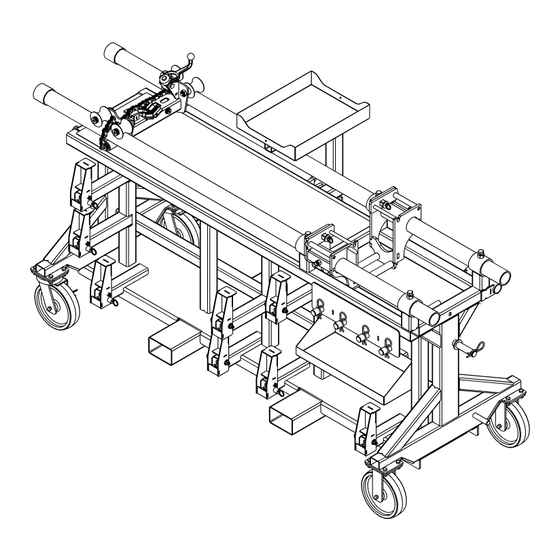
Mobile Bending Station
Assembly, Operating, Safety
and Parts Manual
Read and understand this material before assembling, operating
or servicing the 252 Mobile Bending Station and 254 Hydraulic
Bender. Failure to understand how to safely assemble and
operate this equpment may result in serious injury or death.
www.currenttools.com
Model 252
™
8/2019
Advertisement

Related Manuals for Current Tools 252


Summary of Contents for Current Tools 252
- Page 1 To request a copy, call or write to the address below. All information, specifications and product designs may change due to design improvements or updates and are subject to change without notice. Current Tools does not assume any liability for damages resulting from misuse or incorrect application of its products.
- Page 2 THIS SAFETY SYMBOL is used to call your attention to instructions attaching to or operating with the 252 Mobile Bending Station. that concern your personal safety. It means: ATTENTION! BE AWARE! Failure to do so many result in serious injury or death.
-
Page 3: Important Safety Information
Mobile Bending Station. There are fork pockets provided on the 252 Mobile Bending Station. The maximum height using these fork pockets CAUTION DANGER is 5 feet. DO NOT attempt to lift the 252 Mobile Bending Station by any other means, as there are no lifting points provided. DANGER WARNING Before transporting by vehicle, be sure all components and parts are secured on the 252 Mobile Bending Station. - Page 4 WARNING CAUTION ONLY roll on a firm, flat smooth surface. CAUTION NEVER sit, ride or stand on the Mobile Bending Station. COMPONENTS – 252 MOBILE BENDING STATION DESCRIPTION 281-221 Carriage with vise 252-200 Bender mounting unit...
- Page 5 FOLLOW BAR RETAINER BRACKET SPRING CLIP 90˚ COUPLING ASSEMBLY MAGNETIC PROTRACTOR RAM POSITIONER H.D. CASTER SET – 2 RIGID, 2 SWIVEL FORK POCKETS ® ® * Greenlee and CamTrack are registered trademarks of Greenlee Tools, Inc., which has no affiliation with Current Tools.
- Page 6 MAJOR COMPONENTS – BENDER For complete shoe, follow bar and saddle listing, refer to Model #254 operating manual. All major components will fit Greenlee ® Model #881 CamTrack Bender* ® MAJOR COMPONENTS – PARTS LIST ITEM CATALOG DESCRIPTION QTY. 254-100 HYDRAULIC CYLINDER (INCLUDES ITEM #2) 254-101 CYLINDER MOUNTING BLOCK...
- Page 7 MOUNTING BENDER COMPONENTS ON MOBILE BENDING STATION MAJOR COMPONENTS – BENDER FOLLOW BARS (ALL 4 THIS SIDE) FOLLOW BAR RETAINER BRACKET (2 PER FOLLOW BAR) SADDLES SHOE – 2½" NOTE: Lock casters before mounting STORAGE TRAY or removing components. 1. Pull the pawl release pin on the follow bar retainer brackets and lower the brackets.
- Page 8 MOUNTING BENDER COMPONENTS ON MOBILE BENDING STATION PUMP PUMP PEDESTAL MAJOR COMPONENTS – BENDER PEDESTAL LOCKING PIN SHOE – 4" POSITIONER SHOE – 3½" SHOE – 3" 5. Pull the spring clips out of the mounting holes in the remaining shoe mounting pins and the ram positioner mounting pin.
- Page 9 BENDER ASSEMBLY AND MOUNTING INSTRUCTIONS FRAME SIDE 1. Locate the two frame sides, roller assembly and the two spring clips. ROLLER ASSEMBLY SPRING CLIP 2. Place one frame side onto the roller assembly as shown and secure with a spring clip. NOTE: The collar in the end of the frame side must be facing COLLAR...
- Page 10 BENDER ASSEMBLY AND MOUNTING INSTRUCTIONS GATE IN RAISED POSITION GATE PAWL RING BENDER MOUNTING UNIT CONDUIT SUPPORT TUBE 4. Ensure that the bender mounting unit is installed within the 4 conduit support tubes as shown. Pull the gate pawl ring on both sides of the bender mount unit and raise the gates.
- Page 11 BENDER ASSEMBLY AND MOUNTING INSTRUCTIONS CAUTION Ensure the casters remain locked throughout the bender assembly and mounting process. BENDER MOUNTING UNIT PUMP PEDESTAL TURNED OUTWARD ASSEMBLED FRAME SIDES WITH ROLLER ASSEMBLY 5. Ensure the pedestal with pump is turned outward. Place the assembled frame sides onto the bed of the Mobile Bending Station with the roller assembly resting in the bender mounting unit.
-
Page 12: Hydraulic Cylinder
BENDER ASSEMBLY AND MOUNTING INSTRUCTIONS CYLINDER BLOCK HYDRAULIC CYLINDER WITH BLOCK HYDRAULIC HOSE 7. Insert the hydraulic cylinder with block into the frame sides and pin together, using the two cylinder block pins, in the correct holes for the size conduit you are bending. - Page 13 BENDER ASSEMBLY AND MOUNTING INSTRUCTIONS GATE CLOSED ON BOTH SIDES 8. Lift the frame side assembly with hydraulic cylinder while making sure that the roller slides into the bottom of the bender mounting unit. When the roller is fully seated into the bender mounting unit and the frame sides are vertical as shown, lower the gates of the bender mounting unit until the pawls “click”...
- Page 14 BENDER ASSEMBLY AND MOUNTING INSTRUCTIONS TABLE RAILS RAIL START ROLLER ASSEMBLY 9. Select the follow bar for the size conduit you will be bending. Angle the follow bar and insert it between the frame sides with the end marked “START” as shown. Turn the follow bar so that the rails rest on the roller assembly.
- Page 15 BENDER ASSEMBLY AND MOUNTING INSTRUCTIONS CLEVIS RETAINING CLEVIS CLIP 10. Place the clevis onto the end of the hydraulic cylinder and secure with the clevis retaining clip as shown. 11. Place the correct size bending shoe between the frame sides, making sure the saddle pin hole is located as shown.
- Page 16 BENDER ASSEMBLY AND MOUNTING INSTRUCTIONS — continued 12. Rotate the pump valve lever on the hydraulic pump to the closed position and advance the cylinder until the clevis holes are aligned with the correct conduit type hole (Rigid/IMC or EMT) in the bending shoe.
- Page 17 BENDER ASSEMBLY AND MOUNTING INSTRUCTIONS — continued CARRIAGE WITH VISE 14. Slide the carriage with vise to the far end of the Mobile Bending Station. CARRIAGE WITH VISE CONDUIT 15. Place the conduit between the shoe and follow bar, resting the conduit on the carriage with vise.
- Page 18 BENDER ASSEMBLY AND MOUNTING INSTRUCTIONS — continued VISE CHAIN CONDUIT CARRIAGE 16. Place the vise chain around the WITH VISE conduit and tighten to secure. 17 . Push the end of the follow bar marked “START” towards the bender mounting unit until the “ear”...
- Page 19 BENDER ASSEMBLY AND MOUNTING INSTRUCTIONS — continued 18. While rocking the bender frame, push the bottom of the bending shoe to the position shown for attaching the saddle and saddle pin. PUSH 19. While holding the shoe against the conduit, place the saddle under the conduit with the saddle insert lip SADDLE facing away from the follow bar.
- Page 20 BENDER ASSEMBLY AND MOUNTING INSTRUCTIONS — continued BENDING MARK CONDUIT SADDLE INSERT LIP 20. Once the saddle is pinned onto the shoe, lean the bender forward. Make sure the follow bar moves with it and that the follow bar is flush with the saddle and the bending mark is aligned with the front edge of the saddle insert lip.
- Page 21 BENDER ASSEMBLY AND MOUNTING INSTRUCTIONS — continued 22. Operate the pump to start the bend. WARNING NEVER allow the carriage with vise to contact the conduit support tubes of the Mobile Bending Station. 23. Showing a 45° bend.
- Page 22 BENDER ASSEMBLY AND MOUNTING INSTRUCTIONS — continued 24. Showing a 90° bend. 25. Once the desired degree of bend is complete, remove the level from the conduit. WARNING...
- Page 23 BENDER ASSEMBLY AND MOUNTING INSTRUCTIONS — continued 26. Rotate the pump valve lever to the open position and allow the hydraulic cylinder to retract and raise the bending shoe. 27. Push the follow bar back towards the starting position so that it rests on the table of the Mobile Bending Station.
- Page 24 BENDER ASSEMBLY AND MOUNTING INSTRUCTIONS — continued 28. Remove the saddle from the bending shoe. SADDLE 29. While keeping the conduit under control, release the vise chain. VISE CHAIN...
-
Page 25: Lifting And Transporting
Station. There are fork pockets provided on the 252 Mobile Bending Station. The maximum height using these fork pockets is 5 feet. DO NOT attempt to lift the 252 Mobile Bending Station by any other means, as there are no lifting points provided. - Page 26 EXPLODED VIEW — CARRIAGE WITH VISE PARTS LIST – CARRIAGE WITH VISE ITEM CATALOG DESCRIPTION QTY. 280-1A ROLLER 280-1B ROLLER – FLAT BENDING TABLE 280-2E SPACER 281-004 SCREW – FILLISTER HEAD SLOTTED (5/16–18 × 2") 281-003 SCREW – SHOULDER SOCKET (1/2 × 3") 281-113 ROLLER –...
- Page 27 EXPLODED VIEW — BENDER MOUNTING UNIT PARTS LIST – CARRIAGE WITH VISE ITEM CATALOG DESCRIPTION QTY. 252-004 SCREW, HX HD CAP – 5/8"-11 × 1 1/2" 252-005 WASHER, LOCK – 5/8" 252-209 BAR, CONNECTING 252-211 END, FRAME – RH 252-212 END, FRAME –...
Need help?
Do you have a question about the 252 and is the answer not in the manual?
Questions and answers