Table of Contents
Advertisement
Quick Links
Advertisement
Table of Contents

Related Manuals for Mitsubishi Electric JT-SB216JSH-W-NE


Summary of Contents for Mitsubishi Electric JT-SB216JSH-W-NE
- Page 1 June 2023 No. U200-B HAND DRYER HANDBOOK MODELS JT-SB216JSH-W-NE JT-SB216JSH-H-NE JT-SB216JSH-S-NE JT-SB216KSN-W-NE Nameplate Warning: Repair work must be performed by the manufacturer, its service agent or a similarly qualified person in order to avoid hazards.
-
Page 2: Table Of Contents
8. Principles of operation ............... 12 9. Troubleshooting ..............13-16 10. How to call .................. 16 11. Service inspection list ..............16 12. Overhauling procedures ............17-24 13. Parts catalog ................. 25-57 JT-SB216JSH-W-NE ............26-33 JT-SB216JSH-H-NE ............34-41 JT-SB216JSH-S-NE ............42-49 JT-SB216KSN-W-NE ............50-57... -
Page 3: Safety Precautions
1. Safety precautions Read the following precautions thoroughly before the maintenance, and then inspect and repair the product in a safe manner. The types and levels of danger that may arise if the product is handled incorrectly are described with the warning symbols shown below. -
Page 4: Request For Repair
Request for repair ● Before repairs, take the product off the wall. ● Inspect the earth condition, and repair it if it is incomplete. Make sure that an earth leakage breaker or an over- load protection device is installed, if it is not installed, recommend the dealer to install one. ●... -
Page 5: Names And Functions Of Components
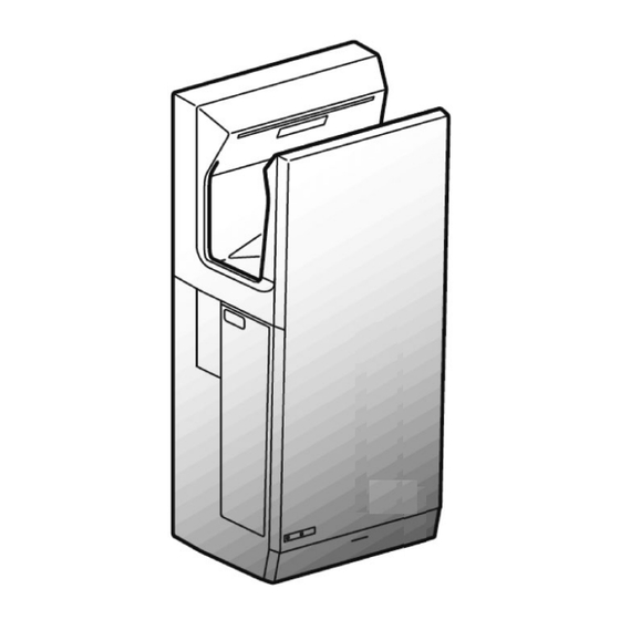
3. Names and functions of components *Shaded areas in the figure indicate antibacterial material. Hand drying area Blue light Black wall area Power control section Switch door Main unit Power switch P o w e O F F Sensor The blue light does not have a sterilizing effect. -
Page 6: Specifications
(Average of the three points: 2 m from the front and both sides of the unit.) • The heater is turned off automatically when ambient temperature reaches 30°C or more. (Applicable models: JT- SB216JSH-W/H/S-NE) 5. Outside dimensions JT-SB216JSH-W-NE, JT-SB216JSH-H-NE, JT-SB216JSH-S-NE, JT-SB216KSN-W-NE Unit: mm ─ 6 ─... -
Page 7: Electrical Wiring Diagrams
6. Electrical wiring diagrams JT-SB216JSH-W-NE, JT-SB216JSH-H-NE, JT-SB216JSH-S-NE, JT-SB216KSN-W-NE ─ 7 ─... - Page 8 ─ 8 ─...
-
Page 9: Circuit Board Diagrams
7. Circuit board diagrams Circuit board diagrams and check points 1 Power circuit board (JT-30P3H [JT-SB216JSH-W/H/S-NE] /JT-30P3 [JT-SB216KSN-W-NE]) <JT-SB216JSH-W/H/S-NE> Heater power supply (With heater ON): 220 V AC, 230 V AC, 240 V AC (JT-30P3H: Between TAB3 and TAB4) Bus voltage (Being stopped): 310 V DC, 324 V DC, 338 V DC (JT-30P3H/JT-30P3: Between TAB5 and 0 V or between TAB6 and 0 V) 15 V Carrier frequency 15 kHz... - Page 10 2 Filter circuit board (JT-30F3) Power supply voltage: 220 V AC, 230 V AC, 240 V AC (JT-30F3: Between TAB20 and TAB21) 3 Control circuit board (JT-30M3A [JT-SB216JSH-W-NE] /JT-30M3 [JT-SB216JSH-H/S-NE] /JT-30M2A [JT-SB216KSN-W-NE]) Clock frequency 8 MHz (JT-30M3A/JT-30M3/JT-30M2A: IC20 14P) Reset input 5 V...
- Page 11 Circuit thermostat characteristics (JT-30M3A/JT-30M3/JT-30M2A: IC20 5P) Temperature Resistance IC20 5P Voltage 20°C 59.3 kΩ 3.44 V 30°C 37.6 kΩ 2.91 V 40°C 24.5 kΩ 2.38 V 4 Light receiving circuit board (JT-30S1) (Upper sensor) 5 Sensor circuit board (JT-30S2) (Middle sensor) 6 Sensor circuit board (JT-30S3) (Lower sensor) 7 Display circuit board (JT-30S5) ─...
-
Page 12: Principles Of Operation
8. Principles of operation Descriptions of circuit operation ( 1 ) Notes for turning the power switch “ON / OFF” 1 When the power switch is turned “ON”, the power lamp (LED1), the heater lamp (LED2) (JT-SB216JSH- W/H/S-NE only, with the heater switch ON), and blue illumination lamps (LED10, 11) turn on after 1.5 sec- onds , and the hand dryer becomes ready for operation. -
Page 13: Troubleshooting
9. Troubleshooting Work precautions • When servicing, be sure to recreate the malfunction two or three times before starting repairs. • When servicing, always take care to keep proper footing. • Before starting the service, always unplug the power cord from the outlet, or turn off the earth leakage breaker when no power cord plug is provided. - Page 14 Error Mode Display Checkpoint Check Method and Remedy Connector discon- Check if the connector CN2 on the power circuit board (JT-30P3H/ Power Heater/Check nection between JT-30P3) or CN5 on the control circuit board (JT-30M3A/JT-30M3/ the circuit boards JT-30M2A) is disconnected. Malfunction of the If no error is found after checking the above, replace the control (Fuse is blown)
- Page 15 Error Mode Display Checkpoint Check Method and Remedy Connector discon- Check if the connector CN5 on the control circuit board (JT-30M3A/ Power Heater/Check nection JT-30M3/JT-30M2A) or CN2 on the power circuit board (JT-30P3H/ JT-30P3) is disconnected. Malfunction of If no error is found after checking the above, replace the power ( Motor signal error) the power circuit circuit board (JT-30P3H/JT-30P3).
-
Page 16: How To Call
Symptom Cause Check Method and Remedy The hand dryer makes Sucking of foreign Check for any foreign matter sticking to the blower (assembly) abnormal noises. matter vanes. Air blow is weak. Clogged filter Check the filter for clogging with dust, etc. Incorrect wiring Check if the motor lead wires of the blower (assembly) (red to TAB7, white to TAB8, black to TAB9) are connected to incorrect... -
Page 17: Overhauling Procedures
12. Overhauling procedures Work precautions • Before replacing parts, follow the instructions described in the troubleshooting. • When servicing, always take care to keep proper footing. • Before starting the service, always unplug the power cord from the outlet, or turn off the earth leakage breaker when no power cord plug is provided. - Page 18 (3) Control circuit board (JT-30M3A/JT-30M3/JT-30M2A) Front panel 1 Draw out the drain tank. 2 Unscrew the clamping screws, and remove the front panel. (Two spl screws 4×16, indicated by ) 3 Unscrew the clamping screw, and remove the cover (micro). (One spl screw 4×16, indicated by ) Cover (micro) 4 Disconnect the lead wires from the control circuit board (JT-30M3A/...
- Page 19 (5) Power circuit board (JT-30P3H/JT-30P3) 1 Remove the front panel. → See (3) 1 to 2. 2 Unscrew the clamping screws, and remove the circuit board (PCB) cover for the power circuit board (JT-30P3H/JT-30P3). (Two PTT screws 4×16, indicated by ) PCB cover 3 Disconnect the lead wires from the power circuit board (JT-30P3H/ JT-30P3), and remove the power circuit board.
- Page 20 4 Unscrew the clamping screw, and remove the terminal block (TB) cover. (One PTT screw 4×6, indicated by ) Terminal block cover 5 Remove the side panel L in the direction of the arrow. Panel (back) Side panel L Assembly precautions •...
- Page 21 (8) Switch (assembly) (with a thermal fuse) 1 Remove the TB fix plate from the side panel L. → See (7) 1 to 7. 2 Remove the power switch lead wires (brown and blue) from the terminal block. (Indicated by ) 3 Unscrew the clamping screw, and remove the terminal block.
- Page 22 Assembly precaution Run the lead wires through the groove of the base. (Indicated by ) 4 Unscrew the clamping screws, and remove the exhaust duct. (Eight PTT screws 4×16, indicated by ) Assembly precautions • Replace the packing used in the disassembled section with a new one.
- Page 23 Assembly precautions • Run the lead wires through the groove of the blower cover. (Indicated by ) • Take care not to pinch the lead wires. (10) Blower (assembly) 1 Remove the blower cover. → See (9) 1 to 5. Set the blower horizontally.
- Page 24 Panel (front) 3 Unscrew the panel (front) and panel holder clamping screws, and remove the panel holders (L and R). (Five PTT screws 4×16, indicated by ) Panel holder L Panel holder R 4 Tilt the panel (front) in the direction of the arrow, and remove it. 5 Remove the sensor holder.
-
Page 25: Parts Catalog
13. Parts catalog Please note the following when using the parts catalog. 1. When ordering parts, the part number, part name, and the number of parts are required. 2. It may take time for you to receive the parts. Make an inquiry about a rush order. 3. -
Page 26: Body Parts
JT-SB216JSH-W-NE Body parts 6 pieces 1 piece 1 piece 1 piece shows accessory parts. ─ 26 ─ JT-SB216JSH-W-NE... - Page 27 Body parts JT-SB216JSH-W-NE Critical Q'ty Name of part Parts No. Remarks pcs/unit safety Side cover Y45 631 806 Switch door Y45 631 808 Side panel L Y45 631 807 PTT screw 4×16 Y45 650 012 Exhaust duct Y45 622 802...
- Page 28 Circuit board parts shows accessory parts. ─ 28 ─ JT-SB216JSH-W-NE...
- Page 29 Circuit board parts JT-SB216JSH-W-NE Critical Q'ty Name of part Parts No. Remarks pcs/unit safety Spacer Y45 650 097 Circuit board Y45 650 177 JT-30S5 Switch cover Y45 650 254 PPT screw 3x8 Y45 650 006 Fix piece Y45 650 882...
-
Page 30: Blower Parts
Blower parts ─ 30 ─ JT-SB216JSH-W-NE... - Page 31 Blower parts JT-SB216JSH-W-NE Critical Q'ty Name of part Parts No. Remarks pcs/unit safety Blower cover Y45 650 880 With a packing Blower stopper Y45 650 240 Blower (assembly) Y45 650 401 Floating rubber Y45 650 237 Heater (PTC) Y45 631 803 With a fuse ...
-
Page 32: Wiring Parts
Wiring parts ─ 32 ─ JT-SB216JSH-W-NE... - Page 33 Wiring parts JT-SB216JSH-W-NE Critical Q'ty Name of part Parts No. Remarks pcs/unit safety Lead wire Y45 650 242 CN18-CN19 Lead wire Y45 650 222 CN7-CN12・CN15 Lead wire Y45 650 241 CN8-CN11 Lead wire Y45 631 219 With a ferrite core ...
-
Page 34: Jt-Sb216Jsh-H-Ne
JT-SB216JSH-H-NE Body parts 6 pieces 1 piece 1 piece 1 piece shows accessory parts. ─ 34 ─ JT-SB216JSH-H-NE... - Page 35 Body parts JT-SB216JSH-H-NE Critical Q'ty Name of part Parts No. Remarks pcs/unit safety Side cover Y45 631 812 Switch door Y45 631 814 Side panel L Y45 631 813 PTT screw 4x16 Y45 650 012 Exhaust duct Y45 622 802 Panel holder L Y45 650 835 Panel holder R...
- Page 36 Circuit board parts shows accessory parts. ─ 36 ─ JT-SB216JSH-H-NE...
- Page 37 Circuit board parts JT-SB216JSH-H-NE Critical Q'ty Name of part Parts No. Remarks pcs/unit safety Spacer Y45 650 097 Circuit board Y45 650 177 JT-30S5 Switch cover Y45 650 254 PPT screw 3x8 Y45 650 006 Fix piece Y45 650 882 Switch (assy) Y45 631 220 ...
- Page 38 Blower parts ─ 38 ─ JT-SB216JSH-H-NE...
- Page 39 Blower parts JT-SB216JSH-H-NE Critical Q'ty Name of part Parts No. Remarks pcs/unit safety Blower cover Y45 650 880 With a packing Blower stopper Y45 650 240 Blower (assembly) Y45 650 401 Floating rubber Y45 650 237 Heater (PTC) Y45 631 803 With a fuse ...
- Page 40 Wiring parts ─ 40 ─ JT-SB216JSH-H-NE...
- Page 41 Wiring parts JT-SB216JSH-H-NE Critical Q'ty Name of part Parts No. Remarks pcs/unit safety Lead wire Y45 650 242 CN18-CN19 Lead wire Y45 650 222 CN7-CN12・CN15 Lead wire Y45 650 241 CN8-CN11 Lead wire Y45 631 219 With a ferrite core ...
-
Page 42: Jt-Sb216Jsh-S-Ne
JT-SB216JSH-S-NE Body parts 6 pieces 1 piece 1 piece 1 piece shows accessory parts. ─ 42 ─ JT-SB216JSH-S-NE... - Page 43 Body parts JT-SB216JSH-S-NE Critical Q'ty Name of part Parts No. Remarks pcs/unit safety Side cover Y45 631 812 Switch door Y45 631 814 Side panel L Y45 631 813 PTT screw 4x16 Y45 650 012 Exhaust duct Y45 622 802 Panel holder L Y45 650 835 Panel holder R...
- Page 44 Circuit board parts shows accessory parts. ─ 44 ─ JT-SB216JSH-S-NE...
- Page 45 Circuit board parts JT-SB216JSH-S-NE Critical Q'ty Name of part Parts No. Remarks pcs/unit safety Spacer Y45 650 097 Circuit board Y45 650 177 JT-30S5 Switch cover Y45 650 254 PPT screw 3x8 Y45 650 006 Fix piece Y45 650 882 Switch (assy) Y45 631 220 ...
- Page 46 Blower parts ─ 46 ─ JT-SB216JSH-S-NE...
- Page 47 Blower parts JT-SB216JSH-S-NE Critical Q'ty Name of part Parts No. Remarks pcs/unit safety Blower cover Y45 650 880 With a packing Blower stopper Y45 650 240 Blower (assembly) Y45 650 401 Floating rubber Y45 650 237 Heater (PTC) Y45 631 803 With a fuse ...
- Page 48 Wiring parts ─ 48 ─ JT-SB216JSH-S-NE...
- Page 49 Wiring parts JT-SB216JSH-S-NE Critical Q'ty Name of part Parts No. Remarks pcs/unit safety Lead wire Y45 650 242 CN18-CN19 Lead wire Y45 650 222 CN7-CN12・CN15 Lead wire Y45 650 241 CN8-CN11 Lead wire Y45 631 219 With a ferrite core ...
-
Page 50: Jt-Sb216Ksn-W-Ne
JT-SB216KSN-W-NE Body parts 6 pieces 1 piece 1 piece 1 piece shows accessory parts. ─ 50 ─ JT-SB216KSN-W-NE... - Page 51 Body parts JT-SB216KSN-W-NE Critical Q'ty Name of part Parts No. Remarks pcs/unit safety Side cover Y45 631 806 Switch door Y45 631 808 Side panel L Y45 631 807 PTT screw 4x16 Y45 650 012 Exhaust duct Y45 622 802 Panel holder L Y45 650 835 Panel holder R...
- Page 52 Circuit board parts shows accessory parts. ─ 52 ─ JT-SB216KSN-W-NE...
- Page 53 Circuit board parts JT-SB216KSN-W-NE Critical Q'ty Name of part Parts No. Remarks pcs/unit safety Spacer Y45 650 097 Circuit board Y45 650 177 JT-30S5 Switch cover Y45 650 254 PPT screw 3x8 Y45 650 006 Fix piece Y45 650 882 Switch (assy) Y45 631 220 ...
- Page 54 Blower parts ─ 54 ─ JT-SB216KSN-W-NE...
- Page 55 Blower parts JT-SB216KSN-W-NE Critical Q'ty Name of part Parts No. Remarks pcs/unit safety Blower cover Y45 650 880 With a packing Blower stopper Y45 650 240 Blower (assembly) Y45 650 401 Floating rubber Y45 650 237 Blower case Y45 650 843 With a packing Cord bush Y45 650 243...
- Page 56 Wiring parts ─ 56 ─ JT-SB216KSN-W-NE...
- Page 57 Wiring parts JT-SB216KSN-W-NE Critical Q'ty Name of part Parts No. Remarks pcs/unit safety Lead wire Y45 650 242 CN18-CN19 Lead wire Y45 650 222 CN7-CN12・CN15 Lead wire Y45 650 241 CN8-CN11 Lead wire Y45 650 255 CN2-CN5 ...
Need help?
Do you have a question about the JT-SB216JSH-W-NE and is the answer not in the manual?
Questions and answers