Table of Contents

Related Manuals for Mitsubishi Electric JT-SB216ESH-W-CE


Summary of Contents for Mitsubishi Electric JT-SB216ESH-W-CE
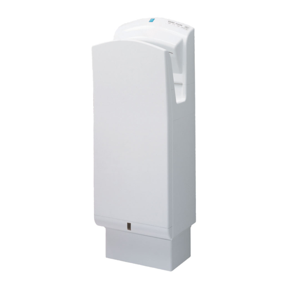
- Page 1 February 2010 No. U131-B HAND DRYER HAND BOOK FOR DEALERS Model: JT-SB216ESH-W-CE JT-SB216ESH-DG-CE Nameplate Repair work should be performed by the manufacturer, its service agent or similarly qualified person in order to avoid hazards.
-
Page 2: Table Of Contents
8. Basic circuit diagram ··························································· 10–16 9. Principles of operation ························································ 17–18 10. Troubleshooting ·································································· 19–23 11. How to call ················································································ 24 12. Service inspection list ······························································· 24 13. Disassembly and assembly ················································ 25–33 14. Parts catalog ······································································· 34–58 JT-SB216ESH-W-CE ······················································ 35–46 JT-SB216ESH-DG-CE ···················································· 47–58... -
Page 3: Safety Precautions
1. Safety precautions GPlease read the following items carefully before using this product, and perform the maintenance and repair work of the product correctly and safely. GThe types and levels of the dangers from mishandling this product are categorized and indicated by the signs shown below. -
Page 4: Features
Items to check during repair work • Inspect the condition of the earth. Correct it if improperly grounded. Also, check to see if an earth leakage breaker or an overload protection device is being installed. If not, recommend the dealer to install one. •... -
Page 5: Improved Points
B Optional function The hand dryer may be installed on the floor using the optional special stand (JP-S15FS-H-E). 3. Improved points Old Model New Model Item (JT-SB216DS) (JT-SB216ESH-W-CE, JT-SB216ESH-DG-CE) Appearance Nozzle Round hole nozzle Hyper-nozzle Noise (dB) Rated power 1010~1200 (During heat accumulation by heater) -
Page 6: Names And Functions Of Components
4. Names and functions of components 4-1 Structure and appearance Power controll section Heater switch H e a t e O F F speed e e d A ir s p knob Switch P o w e door Power O F F switch Power lamp Display... - Page 7 4-2 How to use the hand dryer Power controll section Heater switch Introduction Open the switch door of the power controll section. H e a t e Turn on the power switch. O F F speed Power lamp and heater lamp turn on. (Display) e e d A ir s p knob...
-
Page 8: Specifications
1010~1200 (During heat 50-60 220~240 accumulation) accumulation) JT-SB216ESH-DG-CE (During hand drying: 4.0) (During hand drying: 650) 6. Outside dimensions JT-SB216ESH-W-CE, JT-SB216ESH-DG-CE Mounting plate dimensions Terminal block location Wind volume knob Heater switch Power cord hole (On the back) Switch door Power switch... -
Page 9: Electrical Wiring Diagram
7. Electrical wiring diagram JT-SB216ESH-W-CE, JT-SB216ESH-DG-CE — 9 —... -
Page 10: Basic Circuit Diagram
8. Basic circuit diagram 8-1 Circuit diagram and check points (1) Main circuit (JT-24M) Heater power supply (With heater ON): AC220V, AC230V, AC240V Bus voltage (Being stopped): DC310V, DC324V, DC338V Power supply voltage: AC220V, AC230V, AC240V (JT-24M: Between TAB3-TAB4) (JT-24M: TAB5) (JT-24M: Between TAB1-TAB2) 15V (JT-24M: CN7 1P) 0V (JT-24M: CN7 5P) - Page 11 (2) Sub circuit (JT-24S) — 12 —...
- Page 12 Room thermostat characteristics (JT-24M: CN4 2P) Upper sensor's light receiving signal waveform (JT-24M: CN7 3P) Temperature Resistance CN4 2P Voltage (JT-24S-B: CN14 3P) 10°C 9.01kΩ 2.37V 20°C 6.13kΩ 1.90V (Rises when hands are inserted) 30°C 4.27kΩ 1.50V 100msec (Influence of light emission by the lower sensor) Heater thermostat characteristics (JT-24M: CN9 2P) Lower sensor’s light receiving signal waveform (JT-24M: CN7 2P) Temperature...
- Page 13 8-2 Circuit board diagram and check points (1) Main circuit board (Control circuit board) Bus voltage (Being stopped): DC310V, DC324V, DC338V (JT-24M: TAB5) Heater power supply (With heater ON): AC220V, AC230V, AC240V (JT-24M: Between TAB3-TAB4) 15V (JT-24M: CN7 1P) Power supply voltage: AC220V, AC230V, AC240V (JT-24M: Between TAB1-TAB2) 5V (JT-24M: CN6 1P) 0V (JT-24M: CN7 5P)
- Page 14 (2) Indicator circuit board If the jumper wire (JA) is cut off, the illumination lamp turns off. (3) Wind volume circuit board (4) Light receiving circuit board (5) Light emitting circuit board (6) Illumination circuit board (Blue LED) — 15 —...
- Page 15 Room thermostat characteristics (JT-24M: CN4 2P) Upper sensor's light receiving signal waveform (JT-24M: CN7 3P) Temperature Resistance CN4 2P Voltage (JT-24S-B: CN14 3P) 10°C 9.01kΩ 2.37V 20°C 6.13kΩ 1.90V (Rises when hands are inserted) 30°C 4.27kΩ 1.50V 100msec (Influence of light emission by the lower sensor) Heater thermostat characteristics (JT-24M: CN9 2P) Lower sensor’s light receiving signal waveform (JT-24M: CN7 2P) Temperature...
-
Page 16: Principles Of Operation
9. Principles of operation Description of circuit operation (1) Cautions for turning “ON / OFF” the power switch 1 When the power switch is turned “ON”, the power lamp (LED1), blue emblem lamp (LED4) and illumination lamps (LED10, 11) turn on after 1.5 seconds, and the hand dryer becomes ready for operation. •... - Page 17 (4) Control of the heater temperature 1 Room thermostat detects the room temperature while the heater thermostat monitors the heater temperature. 2 The room thermostat temperature determines the heater control temperature. (The colder the room temperature, the heater control temperature becomes higher, and the hot air temperature is maintained at about 35°C.) 3 Heater turns ON/OFF depending on the heater control temperature, but it does not turn ON in the following occasions.
-
Page 18: Troubleshooting
10. Troubleshooting Work precautions • Before starting the service, try to reproduce the malfunction two or three times. • When servicing, always take care to keep proper footing. • Before starting the service, always unplug the power cord from the outlet, or turn off the earth leakage breaker when no power cord plug is provided. - Page 19 Error Mode Display Cause Check Method and Remedy When 220 ~ 240V is supplied, check the following points. Power Heater Check Blue LED Blown current Check if the current fuses (FUSE1, 2, 3) on the control circuit board are blown or not. fuse If any current fuse is blown, replace the control circuit board.
- Page 20 Error Mode Display Cause Check Method and Remedy Missing or loose Check screws clamping the heat sink for missing or Power Heater Check Blue LED heat sink screws looseness. Defective control If no error is found after checking the above, replace the (Heat sink overheat error) circuit control circuit board.
- Page 21 Error Mode Display Cause Check Method and Remedy Defective control Replace the control circuit board. Power Heater Check Blue LED circuit (Microcomputer signal error) Defective control Replace the control circuit board. Power Heater Check Blue LED circuit (Microcomputer error) Troubles related to the heater Error Mode Display Cause Check Method and Remedy...
- Page 22 Troubles without error display Phenomenon Cause Check Method and Remedy Operation continues after – 1 Turn OFF the power switch once and then back ON again. pulling hands out. 2 Error occurs at the power ON. 3 Take action for the error occurred according to the instruction of troubleshooting.
-
Page 23: How To Call
11. How to call Phenomenon Cause, Inspection and Remedy Wind is too weak to dry quickly. 1Check if the filter is clogged. 2Isn’t the wind volume knob set at the weak position? Water leaks from the product. 1 Check if the drain tank is filled up. (Drain water.) Since the main unit may absorb moisture if the product is operate while the drain tank is full, drain water will flow over when it is filled up beyond its capacity. -
Page 24: Disassembly And Assembly
13. Disassembly and assembly Work precautions • Before replacing parts, follow the instructions described in the troubleshooting. • When servicing, always take care to keep proper footing. • Before starting the service, always unplug the power cord from the outlet, or turn off the earth leakage breaker when no power cord plug is provided. - Page 25 7 Remove the switch cover, and disconnect the relay connector. (Indicated by 8 Remove the volume knob. (Indicated by Assembly precaution Install the volume knob in alignment with the shaft. 9 Remove the volume circuit board clamping nut. (Indicated by (3) Indicator circuit board and illumination circuit board 1 Remove the maintenance cover.
- Page 26 (4) Control circuit board 1 Pull out the drain tank and remove the front panel clamping screws. (Two special screws 4 x 16, indicated by Heater grounding wire (Green) 2 Remove the terminal cover clamping screw. (One PTT screw 4 x 8, indicated by 3 Remove the grounding wire clamping screws.
- Page 27 (5) Blower 1 Remove the control circuit board. See (4) 1 ~ 7. 2 Remove the drain pipe clamping screw. (One PTT screw, 4 x 16, indicated by 3 Remove the blower cover clamping screws. (Four PTT screws 4 x 16, indicated by 4 Remove the cord bush.
- Page 28 3 Remove the clamping screws for the panel holder (right) and the exhaust duct. (Seven PTT screws 4 x 16, indicated by Assembly precaution Start to affix the panel holder from the screw indicated by 4 Lift the sections indicated by , and remove the panel (front).
- Page 29 (7) Light receiving circuit board 1 Remove the blower. See (5) 1 ~ 7. 2 Remove the panel (front). See (6) 2 ~ 4. 3 Remove the clamping screws for the exhaust duct and the side panel. (Four PTT screws 4 x 16, indicated by Assembly precautions •...
- Page 30 7 Remove the board fix plate (back) clamping screws. (Two PTT screws 4 x 16, indicated by Assembly precautions • Replace the packing used in the disassembled section with a new one. • Take care not to twist the packing when replacing it. 8 Remove the light receiving circuit board from the board fix plate (back).
- Page 31 3 Slide and remove the casing. 4 Remove the grounding wire clamping screw. (One special PP screw with the spring washer 4 x 8, indicated by 5 Remove the back cover clamping screws. (Five special screws 4 x 12, indicated by Assembly precautions •...
- Page 32 8 Remove the heater base clamping screws. (Three special screws 4 x 8, indicated by 9 Remove the thermistor (heater thermostat) clamping screw. (One special PPT screw 4 x 8, indicated by Assembly precautions • Wipe off any old oil compound adhered to the end of the thermo lead wire and the heater.
-
Page 33: Parts Catalog
14. Parts catalog Please note the following when using the parts list. 1. When ordering parts, always indicate the part number, part name, and the number of parts required. 2. Parts are not always available, and it may take time for you to receive them. 3. -
Page 34: Jt-Sb216Esh-W-Ce
Model JT-SB216ESH-W-CE Parts No. Name of part Q'ty Critical Remarks Price pcs/unit for safety M45 664 821 Panel(back) X45 608 809 Decoration plate Y45 612 809 Decoration plate Power M45 664 833 Board fix plate(back) H00 163 007 PTT screw 4×16... - Page 35 — 36 — JT-SB216ESH-W-CE...
- Page 36 Model JT-SB216ESH-W-CE Parts No. Name of part Q'ty Critical Remarks Price pcs/unit for safety Y45 612 370 Decoration plate Attention M45 632 803 Hook(upper) M45 664 810 Switch cover Y45 612 356 Decoration plate Switch M45 664 832 Switch door...
- Page 37 31 32 33 34 35 36 37 38 39 40 41 42 43 44 45 46 47 48 49 — 38 — JT-SB216ESH-W-CE...
- Page 38 Model JT-SB216ESH-W-CE Parts No. Name of part Q'ty Critical Remarks Price pcs/unit for safety M45 664 812 Blower cover M45 641 802 Earth fix plate H00 013 076 Lock washer(4) H00 011 008 PT screw 4×8(BS) M45 632 225 Cord bush...
- Page 39 — 40 — JT-SB216ESH-W-CE...
- Page 40 Model JT-SB216ESH-W-CE Parts No. Name of part Q'ty Critical Remarks Price pcs/unit for safety H00 000 487 PTT screw 4×8 M45 664 822 Terminal cover M45 649 226 Bush Y45 608 236 Terminal block ML-20-A37-3P H00 154 005 PPT screw 4×12...
- Page 41 — 42 — JT-SB216ESH-W-CE...
- Page 42 Model JT-SB216ESH-W-CE Parts No. Name of part Q'ty Critical Remarks Price pcs/unit for safety 111. M45 664 837 Casing 112. Y45 612 369 Decoration plate Tank 113. M45 664 839 Side casing 114. M45 664 843 Filter Black 115. M45 664 836 Partition 116.
- Page 43 1 piece 1 piece 8 shows accessory parts. — 44 — JT-SB216ESH-W-CE...
- Page 44 Model JT-SB216ESH-W-CE Parts No. Name of part Q'ty Critical Remarks Price pcs/unit for safety 141. M45 664 225 Lead wire Volume-Display 142. M45 664 219 Lead wire Main-Display 143. M45 664 221 Lead wire Main-Light Receiving 144. M45 664 220 Lead wire Main-Light Emitting 145.
- Page 45 — 46 — JT-SB216ESH-W-CE...
-
Page 46: Jt-Sb216Esh-Dg-Ce
Model JT-SB216ESH-DG-CE Parts No. Name of part Q'ty Critical Remarks Price pcs/unit for safety Y45 612 801 Panel(back) X45 608 809 Decoration plate Y45 612 810 Decoration plate Power M45 664 833 Board fix plate (back) H00 163 007 PTT screw 4×16 M45 664 173 Circuit board JT-24S-B M45 664 857 Packing... - Page 47 — 48 — JT-SB216ESH-DG-CE...
- Page 48 Model JT-SB216ESH-DG-CE Parts No. Name of part Q'ty Critical Remarks Price pcs/unit for safety Y45 612 373 Decoration plate Attention M45 632 803 Hook(upper) M45 664 810 Switch cover Y45 612 356 Decoration plate Switch Y45 612 811 Switch door M45 649 260 Volume knob M45 664 161 Nut M45 664 162 Washer...
- Page 49 31 32 33 34 35 36 37 38 39 40 41 42 43 44 45 46 47 48 49 — 50 — JT-SB216ESH-DG-CE...
- Page 50 Model JT-SB216ESH-DG-CE Parts No. Name of part Q'ty Critical Remarks Price pcs/unit for safety Y45 612 812 Blower cover M45 641 802 Earth fix plate H00 013 076 Lock washer(4) H00 011 008 PT screw 4×8(BS) M45 632 225 Cord bush Y45 606 180 Line filter ESD-R-25D-B M45 664 815 Drain pipe...
- Page 51 — 52 — JT-SB216ESH-DG-CE...
- Page 52 Model JT-SB216ESH-DG-CE Parts No. Name of part Q'ty Critical Remarks Price pcs/unit for safety H00 000 487 PTT screw 4×8 M45 664 822 Terminal cover M45 649 226 Bush Y45 608 236 Terminal block ML-20-A37-3P H00 154 005 PPT screw 4×12 M45 664 816 Box(reactor) M34 981 225 Cord bush Y45 611 179 Reactor...
- Page 53 — 54 — JT-SB216ESH-DG-CE...
- Page 54 Model JT-SB216ESH-DG-CE Parts No. Name of part Q'ty Critical Remarks Price pcs/unit for safety 111. Y45 612 803 Casing 112. Y45 612 372 Decoration plate Tank 113. Y45 612 805 Side casing 114. M45 664 843 Filter Black 115. M45 664 836 Partition 116.
- Page 55 1 piece 1 piece 8 shows accessory parts. — 56 — JT-SB216ESH-DG-CE...
- Page 56 Model JT-SB216ESH-DG-CE Parts No. Name of part Q'ty Critical Remarks Price pcs/unit for safety 141. M45 664 225 Lead wire Volume-Display 142. M45 664 219 Lead wire Main-Display 143. M45 664 221 Lead wire Main-Light Receiving 144. M45 664 220 Lead wire Main-Light Emitting 145.
- Page 57 — 58 — JT-SB216ESH-DG-CE...
- Page 58 Printed in Japan August, 2009 20 <MEE>...
- Page 59 Revision record U131-1 Overview Revision Date 2009-08-04 Page numbers were changed with the addition of the model: JT-SB216ESH-DG-CE (released in July 2009). Page 39 Parts No. of No.77 was D40 022 344, and quantity (Q’ty pcs/unit) was 3. Page 43 Parts No.
Need help?
Do you have a question about the JT-SB216ESH-W-CE and is the answer not in the manual?
Questions and answers