Advertisement
Quick Links
CHAINTECH
Declaration of Conformity
According to 47 CFR, Parts 2 and 15 of the FCC Rules
The following designated product:
9BJL3
EQUIPMENT: MAINBOARD
MODEL NO.: 9BJL3
Intel Socket 478
Intel 845 + ICH2
ATX Motherboard
is a Class B digital device that complies with 47 CFR Parts 2 and 15 of the FCC
Rules. Operation is subject to the following two conditions:
1. This device may not cause harmful interference.
2. This device must accept any interference received, including interference that
may cause undesired operation.
User's Guide
This declaration is given to the manufacturer:
CHAINTECH-EXCEL COMPUTER INC.
4427 Enterprise St. Fremont, CA 94538, U.S.A.
http://www.chaintech-excel.com
Chaintech President: Simon Ho
Signature:
Version 1.0
Advertisement

Related Manuals for CHAINTECH 9BJL3


Summary of Contents for CHAINTECH 9BJL3
- Page 1 According to 47 CFR, Parts 2 and 15 of the FCC Rules The following designated product: 9BJL3 EQUIPMENT: MAINBOARD MODEL NO.: 9BJL3 Intel Socket 478 Intel 845 + ICH2 ATX Motherboard is a Class B digital device that complies with 47 CFR Parts 2 and 15 of the FCC Rules.
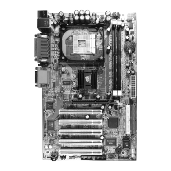
- Page 2 1-2 Package Contents .................... 2 Part 15 of the FCC Rules. These limits are designed to provide reasonable protection against harmful interference 1-3 9BJL3 Motherboard Diagram ................. 3 in a residential installation. This equipment generates, uses, and can radiate radio frequency energy. If this equipment is not installed and used in accordance with the manufacturer's instructions, it may cause harmful 1-4 9BJL3 Motherboard Layout ................
- Page 3 Chapter 1 Chapter 1 One SPP/ECP/EPP parallel port Introduction Chapter 1 One floppy disk drive connector supports up to 2.88MB 1-1 Product Specifications Fast Ethernet Controller Processor Onboard Realtek RTL8101L supports 10/100Mbps fast Ethernet Supports Intel Celeron/Pentium 4 Socket 478 CPU Boot-Block Flash ROM Supports Intel Celeron/Pentium 4 system bus at 400/533MHz Award system BIOS supports PnP, APM, DMI, ACPI, &...
- Page 4 Chapter 1 Chapter 1 1-3 9BJL3 Motherboard Diagram 1-4 9BJL3 Motherboard Layout Page 9 Page 7 Page 6 Page 10 Page 7 Page 9 Page 9 Page 11 Page 10 Page 10 Page 8 Page 10 Page 10 Page 11...
- Page 5 Chapter 2 Chapter 2 By turning on your system’s power. Enable the CMOS Setup Utility by pressing the Hardware Setup Chapter 2 delete key when your BIOS identification screen appears, then go to the Frequency/ If your motherboard has already been installed in your computer you may still need Voltage control option and select your CPU clock ration and CPU clock speed to refer to this chapter if you plan to upgrade your system's hardware.
- Page 6 Advanced Power Management Suspend mode. This mode is used for saving electricity when the computer is All cables that provided by CHAINTECH come with a security-proof. not in use for long periods of time. The Soft-OFF by PW 1 / 3 (ATX Power Supply Connector)
- Page 7 Chapter 2 Chapter 2 FD1 (Floppy Connector) CN17 (Blue LED Mode Jumper) The motherboard provides a standard floppy disk These features work entirely the same as the power drive connector that supports 360K, 720K, 1.2M, indicator LED, both shows the system’s power status. The 1.44M and 2.88M floppy disk types, use this only difference is that this one is blue while the other is red connector to connect 34 pins of Floppy.
- Page 8 Chapter 2 Chapter 3 CN24 (Front Audio Connector) BIOS Setup Program Chapter 3 This connector give you the option of a front panel audio jack cable ext. to be plug into a special custom designed Phoenix-Award BIOS ROM has a built-in setup program that allows users to modify system case.
- Page 9 Chapter 3 Chapter 3 This category identifies up to four IDE hard disk drives that have been installed in First/Second/Third/Boot Other Device the computer. This section does not show information on other IDE devices such as This option sets the sequence of drives BIOS attempts to boot from after POST CD-ROM drives or other hard drive type such as SCSI drives.
- Page 10 Chapter 3 Chapter 3 APIC Mode When set to Manual, you can select the RAS Precharge Time(tRP), RAS Active This item can enable or disable the APIC (Advanced Programmable Interrupt Time(tRAS), RAS to CAS Delay(tRCD), CAS Latency Setting, and DRAM Addr/Cmd Rate.
- Page 11 Chapter 3 Chapter 3 AGP Aperture Size auto-detect the optimal number of block read/writes per sector the drive can This function determines the amount of system memory that is given to the AGP support. card. Options range from 4MB to 256MB. This is a dynamic memory allotment in OnChip PCI Device that the AGP card will only use the amount of memory that it needs.
- Page 12 Chapter 3 Chapter 3 parallel port. This section provides information on the Green PC power management functions. By choosing the Power Management Setup option from the CMOS Setup Utility 6. Parallel Port Mode menu (Figure 3-1), the screen below is displayed. This sample screen contains the Select an operating mode for the onboard parallel (printer) port.
- Page 13 Chapter 3 Chapter 3 requires an IRQ assignment to wake up the system and perform tasks. This 5. Power On by Alarm assignment is complaint with the APM 1.2 complaint operating systems. When enabled, this setting allows the system to turn back on at a designated time of the month.
- Page 14 Chapter 3 Chapter 3 3-7 Frequency/Voltage Control 3-1). When the Security Option function is set to Setup, a password is required to By choosing the Frequency/Voltage Control option from the CMOS Setup Utility enter BIOS and change BIOS settings. When the Security Option function is set to menu (Figure 3-1), the screen below is displayed.
- Page 15 Chapter 4 Chapter 4 4-3 Audio Driver Setup DRIVER Setup Chapter 4 1. Click [Audio Driver] Insert the support CD that come with your motherboard into your CD-ROM driver 2. Click [Next >] to continue installation or double-click the CD drive icon in [My computer] to open the setup screen. 3.
- Page 16 URL: http://www.chaintech.com.tw E-mail (Sales): sales@chaintechusa.com E-mail: sales@chaintech.com.tw CHAINTECH reserves all the rights to change this manual .All information is subject to change without notice. For China CHAINTECH, SHENZHEN For UK: CHAINTECH UK., LTD. Room 301, Nanguang Building, No.1004, 7200 The Quorum, Oxford Business Park North...
Need help?
Do you have a question about the 9BJL3 and is the answer not in the manual?
Questions and answers