Advertisement
Quick Links
Advertisement

Related Manuals for Mitsubishi Electric Apricot FT600


Summary of Contents for Mitsubishi Electric Apricot FT600
- Page 1 Apricot SERIES FT600 Handbook COMPACT...
- Page 2 APRICOT FT S ERIES with PentiumII® processor OWNER’S HANDBOOK...
- Page 3 Intel and PentiumII ® are registered trademarks of Intel Corporation. Microsoft, MS-DOS, Windows ® 95 and Windows ® NT are registered trademarks of Microsoft Corporation in the US and other countries. Other trademarks mentioned within this document and not listed above are the properties of their respective owners.
- Page 4 CONTENTS Safety and Regulatory notices General Maintenance and Transporting Standards and Legalities Power connection Welcome Unpacking Pictorial guide to the system unit Removing panels General advice Connecting the components Getting Started Turning on the PC Power saving Shutting down the PC Using the computer for the first time Electronic Fingerprinting Backing-up the pre-installed software...
- Page 5 C o n t e n t s Expansion Cards Configuring the card Installing the card Reserving ISA legacy resources Telling Windows about the new hardware Motherboard Features & Upgrades Motherboard layout and features Motherboard jumper settings Motherboard IRQs and DMA channels Replacing the configuration battery Adding more memory Adding more video memory...
- Page 6 SAFETY AND REGULATORY NOTICES General Electrical The computer uses a safety ground and must be earthed. The system unit AC power cord is its ‘disconnect device’. Ensure that the system unit is positioned close to the AC power outlet and that the plug is easily accessible.
- Page 7 S A F E T Y & R E G U L A T O R Y N O T I C E S Ergonomic When positioning the system unit, monitor and keyboard, take into account any local or national regulations relating to ergonomic requirements.
- Page 8 S A F E T Y & R E G U L A T O R Y N O T I C E S Maintenance Switch off and disconnect all cables before attempting to clean the computer. Do not use sprays, solvents or abrasives that might damage the system unit surface.
- Page 9 This system complies with the CE Marking Directive and its strict legal requirements. Use only parts tested and approved by Mitsubishi Electric PC Division. Failure to do so may result in invalidating both the compliance and your warranty. All expansion cards, drives and peripherals must carry the CE mark...
- Page 10 S A F E T Y & R E G U L A T O R Y N O T I C E S Power Connection Typical AC plugs 250V 125V 250V 250V 250V BS1363A SHUCO NEMA 5-15P SRAF 1962/DB16/87 ASE 1011 U.
- Page 11 S A F E T Y & R E G U L A T O R Y N O T I C E S Connecting to the AC power supply IMPORTANT Any peripheral equipment that requires an AC power cord must be earthed. Use the following guidance to connect the components together.
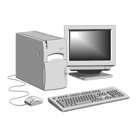
- Page 12 WELCOME This chapter gives you a quick tour of your new Apricot FT series Computer. As soon as you’ve unpacked the components and assembled them, you should progress to the next chapter, Getting Started. Throughout this manual ‘Windows’ means Microsoft Windows 95 or Windows NT 4.x, unless otherwise stated.
- Page 13 W e l c o m e Pictorial guide to the system unit COM PACT Infra-red sensor (optional) CD activity indicator Hard disk activity indicator Lockable front door Power Mode indicator CD emergency eject hole button CD E button OWER JECT CD-ROM disc drawer (platter) Diskette drive...
- Page 14 W e l c o m e On-board video out (monitor) Audio output (speaker) jack Video out port (option) Double USB port Parallel (printer) port Security loop for cable or padlock PS/2 Mouse port AC out for monitor PS/2 keyboard port Voltage selection switch Serial (modem) port 1 AC power inlet from AC supply...
- Page 15 W e l c o m e The audio output socket is intended for headphones or a pair of external self-powered loudspeakers. Rear port ident symbols (from previous illustration) Speaker Line out Mic. COM1 Key’bd Mouse Print Video Mon. 10101 Removing panels For normal access to the interior of the system unit, only the right side panel, and possibly the top panel, need to be removed.
- Page 16 W e l c o m e Slide the panel carefully towards the rear of the system using the handle provided. After about 2 to 3 cm of movement it is possible to lift the panel vertically, clear of the system. Some models incorporate a security feature, controlled in BIOS Setup, that can detect if the caselock has been unlocked while the computer was turned off.
- Page 17 W e l c o m e Power supply First (master) hard disk Housing for removable media drives (e.g. CDROM) Floppy diskette drive Alarm connection to case lock (may be fitted to front door) Memory (DIMM) sockets Pentium® II processor Riser board for expansion Video memory (SoDIMM) socket Rear hard drive bay (2 drives)
- Page 18 W e l c o m e General advice This computer is designed to be used in a normal home or office environment. Here are a few hints for choosing a suitable site: Place the system unit flat on a sturdy, level surface, free from vibration.
- Page 19 W e l c o m e Connecting the components Use the following guidance to connect the components together. It is important that you take each step in the order indicated. Before connecting any components, ensure that the AC power supply is switched off or disconnected, and that the system unit, the monitor, and any peripherals are turned off.
- Page 20 GETTING STARTED You should read this chapter even if you do not read any other. It provides important information to help you to use your Apricot PC safely and efficiently. Turning on the PC To turn on the computer, simply press the P button.
- Page 21 G e t t i n g S t a r t e d Power saving Use the P button to turn the computer on and change power OWER modes. The colour of the indicator light on the P button OWER shows the current power mode: [red]...
- Page 22 G e t t i n g S t a r t e d Automatic power saving If you leave your PC running Windows 95 or Windows for Workgroups without doing anything, it moves automatically to Suspend [yellow] mode. Press the P button to wake it up OWER again.
- Page 23 G e t t i n g S t a r t e d After you shut down the PC, wait at least 5 seconds before turning it on again. The computer may not initialise itself properly if you turn it off then on again in quick succession. Emergency shut down In exceptional circumstances, you can put your PC into Off [red] mode without shutting down Windows first.
- Page 24 G e t t i n g S t a r t e d Electronic Fingerprinting Electronic Fingerprinting allows you to ‘brand’ your computer by storing personal information in its permanent memory. If you include your name, address and phone number this will aid the police if your computer is stolen.
- Page 25 Apricot PCs arrive with a pre-installed copy of Windows 95, Windows NT or Windows for Workgroups. Additional software may be pre-installed at the factory or by your Mitsubishi Electric PC supplier. We recommend that you copy or ‘back-up’ any pre-installed software soon after setting up the system.
- Page 26 Windows is sure to display correctly whatever monitor you have. Most modern monitors, including Mitsubishi Electric monitors, can display higher resolutions than standard VGA. You can change the setting to one that more closely matches your own monitor, to get the best performance from it.
- Page 27 G e t t i n g S t a r t e d If your hard disk is larger than 2 gigabytes If your Apricot PC is pre-installed with Windows 95, the entire hard disk is initially formatted as one partition. If you have Windows NT, the first 2 Gbytes are formatted (using FAT) as a primary partition.
- Page 28 REMOVABLE MEDIA DRIVES Diskette drive Your Apricot Server is fitted with a 1.44 Mbyte diskette drive. This accepts either 1.44 Mbyte (HD) or 720 Kbyte (DD) diskettes. Each diskette has a rigid plastic cover, with a metal shutter that guards the disk surface. Never touch the exposed surface under the shutter –...
- Page 29 R e m o v a b l e m e d i a d r i v e s Ejecting a diskette Wait until the drive’s activity indicator is unlit, then press the button. EJECT If a diskette becomes stuck in the drive, perhaps because its label has peeled back, do not attempt to remove it with tweezers or any similar implement;...
- Page 30 R e m o v a b l e m e d i a d r i v e s CD-ROM drive The CD-ROM drive can retrieve multimedia data from CD-ROM discs and multi-session Photo-CD discs. It can also play normal music CDs (the drive has its own headphone jack and associated volume control).
- Page 31 R e m o v a b l e m e d i a d r i v e s Inserting a compact disc Press the button on the front of drive. EJECT Place the CD centrally, printed side up, on the platter. Push the button again, or gently push the front of the EJECT...
- Page 32 R e m o v a b l e m e d i a d r i v e s DAT tape drive (option) It is recommended to regularly make a backup of the software on the system hard drives. A DAT tape drive is one of the simplest and most convenient methods.
- Page 33 R e m o v a b l e m e d i a d r i v e s Inserting a DAT tape COM PAC Hold the cassette with its metal plate downward and the open tape edge towards the computer. Without using undue force, press the cassette against the drive tape slot.
- Page 34 EXPANSION CARDS Expansion cards (also known as expansion boards, controllers or adapters) are small self-contained circuit boards which extend the capabilities of the computer. For example, a graphics card could provide more specialised video functions than those offered by the on-board video system, or a modem card could provide a connection to the Internet via a telephone line.
- Page 35 E x p a n s i o n C a r d s Configuring the card Part of the installation procedure for an expansion card involves setting up or “configuring” the card so it will work correctly in the computer.
- Page 36 E x p a n s i o n C a r d s ISA Interrupt request level (IRQ) The “interrupt request level” or “IRQ” is the means by which the expansion card sends a signal to get the attention of, or interrupt, the processor.
- Page 37 E x p a n s i o n C a r d s Base memory address Some expansion cards are fitted with memory of their own, usually read-only memory (ROM) containing functional extensions to the computer’s BIOS (basic input/output system) ROM. Some cards also have random-access memory (RAM).
- Page 38 E x p a n s i o n C a r d s Installing the card Read all these instructions through before attempting to install any expansion card. WARNING Never carry out any work inside the computer with AC power applied.
- Page 39 E x p a n s i o n C a r d s Position the expansion card alongside the slot in which you wish to install it. Align the rear of the card with the slot in the rear of the system unit, and, if the card is full length, align the front of the card with the card guide.
- Page 40 E x p a n s i o n C a r d s Reserving ISA legacy resources If you have just installed an ISA card, your first task after turning on the computer is to run the BIOS Setup utility and reserve or exclude the legacy resources (that is, the interrupts and UMB regions) used by the card.
- Page 41 CAUTION Do not alter any jumpers or switch settings other than those identified in this chapter, unless told to by your Mitsubishi Electric PC supplier or an authorised maintainer. Otherwise, you may damage the system processor, the motherboard, or both.
- Page 42 M o t h e r b o a r d f e a t u r e s a n d u p g r a d e s Detailed view PL18 PL19 J 5,6,7,8 PL26 PL27 PL25 PL23 FT SERIES HANDBOOK...
- Page 43 M o t h e r b o a r d f e a t u r e s a n d u p g r a d e s Major board features 1 Aux. audio input (option) 9 ‘Wake on LAN’ connect 17 Processor heat sense input 2 Floppy drive interface 10 ‘Wake on MODEM’...
- Page 44 M o t h e r b o a r d f e a t u r e s a n d u p g r a d e s LM78 System Monitor The motherboard has an on board monitoring system provided by an LM78 device.
- Page 45 M o t h e r b o a r d f e a t u r e s a n d u p g r a d e s On-board video disabling (J1) If you install a video adapter expansion card, the computer should automatically detect this and disable the on-board video adapter.
- Page 46 M o t h e r b o a r d f e a t u r e s a n d u p g r a d e s BIOS upgrade and reprogram (J12, J2) These jumpers should not normally be changed except by a service engineer or at the direction of a service engineer.
- Page 47 M o t h e r b o a r d f e a t u r e s a n d u p g r a d e s Motherboard IRQs Components Interrupts (IRQs) System timer Keyboard controller PIC daisy chain Serial port 2 Serial port 1 Audio...
- Page 48 M o t h e r b o a r d f e a t u r e s a n d u p g r a d e s Replacing the configuration battery The computer keeps a record of its current hardware configuration in a CMOS memory chip which is sustained by a small battery.
- Page 49 M o t h e r b o a r d f e a t u r e s a n d u p g r a d e s Upgrading the motherboard CAUTION Care must be taken in the purchase of upgrade parts to ensure both compatibility with the system and the compliance with appropriate approvals and certification, e.g.
- Page 50 M o t h e r b o a r d f e a t u r e s a n d u p g r a d e s Fitting and removing DIMMs Read all of these instructions through carefully before you start work.
- Page 51 M o t h e r b o a r d f e a t u r e s a n d u p g r a d e s Fitting a DIMM Do not use excessive force. If the module will not fit easily, remove it and start again.
- Page 52 M o t h e r b o a r d f e a t u r e s a n d u p g r a d e s Removing a DIMM Do not use excessive force. If the module will not come free easily, check that the holding clips are clear of the module ends.
- Page 53 M o t h e r b o a r d f e a t u r e s a n d u p g r a d e s Adding more video memory Video memory is memory reserved for use by the on-board video controller.
- Page 54 M o t h e r b o a r d f e a t u r e s a n d u p g r a d e s The processor assembly To remove the existing processor Turn off the computer and unplug all power cords. Take suitable anti-static precautions and remove the system cover.
- Page 55 M o t h e r b o a r d f e a t u r e s a n d u p g r a d e s Disconnect the heat sensor connector (marked ‘C’ on the illustration) that goes to PL9 on the motherboard. See ‘A’...
- Page 56 M o t h e r b o a r d f e a t u r e s a n d u p g r a d e s Refit the heatsink support, making sure that it is correctly and fully seated on the pins.
- Page 57 DRIVE UPGRADES This chapter describes how to add further drives to your computer. The forward drive bay can accommodate two hard disk drives. Either drive may be of 3.5 or 5.25 form factor. These may be E-IDE drives, or SCSI drives if you have a SCSI host bus adaptor expansion card.
- Page 58 D r i v e U p g r a d e s WARNING Never carry out any work inside the computer with AC power applied. Always shut down the computer and unplug all power cords before removing the top cover. Configuring a Hard Disk Drive (HDD) HDDs typically require configuration, perhaps by altering jumpers on the drive itself, prior to installation.
- Page 59 D r i v e U p g r a d e s Installing in the forward drive bay To install a second (slave) hard disk drive in the forward drive bay: Turn off the computer and unplug all power cords. If there is a diskette in the diskette drive, remove it.
- Page 60 D r i v e U p g r a d e s Installing in the rear drive bay The rear drive bay is intended for 3.5-inch SCSI hard disk drives. Turn off the computer and unplug all power cords. If there is a diskette in the diskette drive, remove it.
- Page 61 D r i v e U p g r a d e s Windows 95 Use the MS-DOS Fdisk program to create partitions on the disk. The Fdisk program can be run in an MS-DOS window within Windows. Type Help Fdisk at the MS-DOS command prompt to find out more.
- Page 62 D r i v e U p g r a d e s Configuring the removable media drive Removable-media drives sometimes require configuration, perhaps by altering jumpers on the drive itself, prior to installation. Configuration details vary from drive to drive: a second ATA drive needs to be configured as a slave drive, and a SCSI drive requires that its device ID number be set (the boot SCSI drive is usually drive ‘0’).
- Page 63 D r i v e U p g r a d e s 8b. If you are fitting a second ATA device, attach the spare connector on the CD-ROM ribbon (signal) cable to the new drive. HINT If your computer does not already have a CD-ROM drive, a suitable ribbon cable should have been supplied with the new drive.
- Page 64 BIOS SETUP & POST BIOS (pronounced “bye-oss”) stands for ‘basic input/output system’. The BIOS mediates between the computer’s hardware – the processor, memory, and so on – and its software – the operating system and your programs. The BIOS program is kept in permanent, read-only memory or ROM (although if necessary it can be upgraded by an authorised maintainer).
- Page 65 B I O S S e t u p & P O S T BIOS Setup To start the BIOS Setup utility: Turn on or restart your computer. Wait until the Mitsubishi Electric logo appears on the screen. Press the 2 key. If you have previously defined a Supervisor password, you are prompted for it before BIOS Setup starts.
- Page 66 B I O S S e t u p & P O S T Changeable fields are enclosed in square brackets. To select an item, use the arrow keys to move the cursor to the field you want. Then use the (+) and (–) keys to select a value for that field.
- Page 67 PCI/PNP ISA UMB Region Exclusion as required. Multi-boot facility If you restart your computer and press the key while the Mitsubishi Electric logo is on the screen, a diagnostics screen appears, followed by a menu similar to the following: Boot Menu 1. Diskette Drive 2.
- Page 68 B I O S S e t u p & P O S T In general, you should respond to these errors as follows: Shut down the computer, wait 20 to 30 seconds, and then turn it on again to see if the problem is still reported. Check that all external cables are securely connected.
- Page 69 B I O S S e t u p & P O S T Keyboard error [nn] or Keyboard controller error There is a problem with the keyboard or (less likely) the standard I/O controller on the motherboard. If POST discovers a stuck key it displays its scan code.
- Page 70 B I O S S e t u p & P O S T Terminal POST errors and beep codes There are several POST routines that shut down the computer if they fail. If possible, the BIOS displays a two-digit hexadecimal code and/or sounds a sequence of beeps to identify the point at which POST failed.
- Page 71 TROUBLESHOOTING This chapter offers advice if you suspect a fault with your computer. It is concerned mainly with problems caused by the computer itself; problems more often arise from other sources such as your operating system or application software. It must also be remembered that it can be very easy to leave off or dislodge cables inside the computer when fitting expansion cards, or upgrading the motherboard, or indeed anything that requires temporary removal of the system cover.
- Page 72 T r o u b l e s h o o t i n g Power-on self-test (POST) Whenever the computer is turned on, the BIOS POST routine tests various hardware components, including memory, and compares the actual configuration of the computer with that recorded in CMOS memory.
- Page 73 T r o u b l e s h o o t i n g another system diskette, if possible. Make sure that a boot device is correctly specified with the BIOS Setup utility. If the problem persists contact your supplier or authorised maintainer.
- Page 74 T r o u b l e s h o o t i n g grease and dust from the rollers inside the mouse with a cotton swab moistened with a solvent cleaner. Keyboard If the keyboard response is poor, something may be trapped under the keys.
- Page 75 T r o u b l e s h o o t i n g diskettes during certain other operations, or until you are about to exit the program. CD-ROM drive If you have problems accessing a CD, check that you have allowed a few seconds for the disk to spin up to full speed, that the disk is the correct way up in the drive (printed side upwards) and that it is a data CD.
- Page 76 EQUIPMENT LOG Use this equipment log to record information about your PC. In particular, you must keep a record of the 12-digit fall-back password of the Electronic Fingerprinting security feature (see the Getting Started chapter for more information). Record the password in the space provided below, then store this page (or the whole manual) in a safe place.
- Page 77 E q u i p m e n t l o g Expansion cards Manufacturer Description Serial number Other information It may be useful to note any additional information here such as date of purchase, supplier, etc., along with the phone number of your maintenance provider.
- Page 78 16326031 MITSUBISHI ELECTRIC MITSUBISHI ELECTRIC PC DIVISION PC DIVISION Apricot Computers Limited Apricot Computers Limited 3500 Parkside Niederlassung Deutschland Birmingham Business Park Gothaer Strasse 27 Birmingham B37 7YS 40880 Ratingen United Kingdom Germany Tel +44 (0) 121 717 7171 Tel +49 (0) 2102 4556...
Need help?
Do you have a question about the Apricot FT600 and is the answer not in the manual?
Questions and answers